sport mode MINI 3 door 2014 Owner's Manual
[x] Cancel search | Manufacturer: MINI, Model Year: 2014, Model line: 3 door, Model: MINI 3 door 2014Pages: 240, PDF Size: 11.05 MB
Page 42 of 240
Switching on interior lights and
courtesy lights
Press button on the remote control
with the vehicle locked.
This function is not available, if the interior
lamps were switched off manually.
If the button is pressed within 10 seconds of
when the vehicle was locked Interior motion
sensor and tilt alarm sensor of the anti-theft
warning system, refer to page 44, are turned
off. After locking, wait 10 seconds before press‐
ing the button again.
Panic mode
You can trigger the alarm system if you find
yourself in a dangerous situation.
Press button on the remote control for
at least 3 seconds.
To reel off the alarm: press any button.
Unlock the tailgate Press button on the remote control for
approx. 1 second.
The tailgate opens slightly, regardless of
whether the vehicle was previously locked or
unlocked.
Depending on the features and the country
version, it is also possible to have door un‐
locked. Create the settings, refer to page 42.
If the doors were not unlocked, the tailgate is
locked again as soon as it is pushed closed.
Do not place the remote control in the
cargo area
Take the remote control with you and do not
leave it in the cargo area; otherwise, the re‐
mote control is locked inside the vehicle when
the tailgate is closed. ◀Provide edge protection
Sharp objects or those with edges can hit
the rear window while driving and damage the
heat conductors of the rear window. Provide
edge protection. ◀
Malfunction Remote control detection by the vehicle can
among others be malfunctioning under the fol‐
lowing circumstances:▷Interference of the radio connection from
transmission towers or other equipment
with high transmit power.▷Shielding of the remote control due to
metal objects.▷Interference of the radio connection from
mobile phones or other electronic devices
in direct proximity.
Do not transport the remote control together
with metal objects or electronic devices.
In the case of a malfunction, unlock and lock
the vehicle using the integrated key, refer to
page 39.
For US owners only The transmitter and receiver units comply with
part 15 of the FCC/Federal Communication
Commission regulations. Operation is governed by the following:
FCC ID:
▷LX8766S.▷LX8766E.▷LX8CAS.▷LX8CAS2.▷MYTCAS4.
Compliance statement:
This device complies with part 15 of the FCC
Rules. Operation is subject to the following two
conditions:
▷This device may not cause harmful interfer‐
ence, andSeite 38CONTROLSOpening and closing38
Online Edition for Part no. 01 40 2 957 280 - X/14
Page 46 of 240
▷Shielding of the remote control due to
metal objects.▷Interference of the radio connection from
mobile phones or other electronic devices
in direct proximity.
Do not transport the remote control together
with metal objects or electronic devices.
In the case of a malfunction, unlock and lock
the vehicle using the buttons of the remote
control or using the integrated key, refer to
page 39.
Adjusting Unlocking The settings are saved in the active profile. Per‐
sonal Profile, refer to page 35.
Doors
1. "Settings"2."Doors/key"3. Select the symbol.4.Select the desired function.▷"Driver's door only"
Only the driver's door and the fuel filler
flap are unlocked. Pressing again un‐
locks the entire vehicle.▷"All doors"
The entire vehicle is unlocked.▷On 3-door models:
"Comfort access"
The entire vehicle is unlocked. Pressing
again lowers the window when the
door is subsequently opened.Tailgate
Depending on optional features and country
version, this setting is not offered in some
cases.1. "Settings"2."Doors/key"3. Select the symbol.4.Select the desired function.▷"Tailgate"
Only the tailgate is unlocked.▷"Tailgate + door(s)"
The tailgate and the doors are un‐
locked.
Locking
The settings are saved in the active profile. Per‐
sonal Profile, refer to page 35.
1. "Settings"2."Doors/key"3.Select desired setting.▷"Lock if no door is opened"
The vehicle locks automatically after a
short period of time if no door is
opened.▷"Lock after start driving"
The vehicle locks automatically after
you drive off.
Confirmation signals from the vehicle
1."Settings"2."Doors/key"3.Select desired setting.▷"Acoustic sig. lock/unlock"
Unlocking is signaled by one honk of
the horn.▷"Flash when lock/unlock"
Unlocking is signaled by two flashes,
locking by one.Seite 42CONTROLSOpening and closing42
Online Edition for Part no. 01 40 2 957 280 - X/14
Page 48 of 240
Interior motion sensorThe windows and glass sunroof must be closed
for the system to function properly.
Avoiding unintentional alarms
The tilt alarm sensor and interior motion sensor
can be switched off together, such as in the fol‐
lowing situations:▷In automatic car washes.▷In duplex garages.▷During transport on trains carrying vehicles,
at sea or on a trailer.▷With animals in the vehicle.
Switching off the tilt alarm sensor and
interior motion sensor
Press the remote control button again
within 10 seconds as soon as the vehi‐
cle is locked.
The indicator lamp lights up for approx. 2 sec‐
onds and then continues to flash.
The tilt alarm sensor and interior motion sensor
are turned off, until the vehicle is locked again.
Switching off the alarm
▷Unlock vehicle with the remote control or
reel on the ignition, if needed through
emergency detection of remote control, re‐
fer to page 35.▷With Comfort Access: If you are carrying the
remote control on your person, grasp the
driver side or front passenger side door
handle completely.
Unlock vehicle with the remote control or reel
on the ignition, if needed through emergency
detection of remote control, refer to page 35.
Power windows
Note Take the remote control with you
Take the remote control with you when
leaving the vehicle so that children, e.g., cannot
operate the power windows and injure them‐
selves. ◀
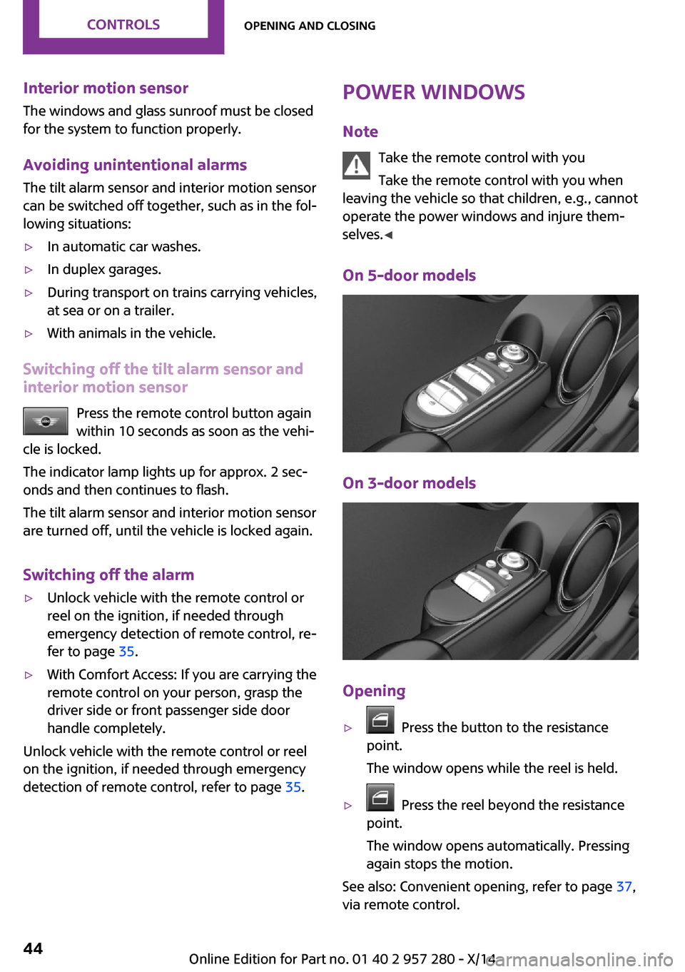
On 5-door models
On 3-door models
Opening
▷ Press the button to the resistance
point.
The window opens while the reel is held.▷ Press the reel beyond the resistance
point.
The window opens automatically. Pressing
again stops the motion.
See also: Convenient opening, refer to page 37,
via remote control.
Seite 44CONTROLSOpening and closing44
Online Edition for Part no. 01 40 2 957 280 - X/14
Page 49 of 240
ClosingKeep the closing path clear
Monitor closing and make sure that the
closing path of the window is clear; otherwise,
injuries may result. ◀
Pull switch up.
The window closes while the reel is held.
See also: closing by means of Comfort Access, refer to page 41.
Pinch protection system If closing force exceeds a specific margin as a
window closes, closing is interrupted.
The window reopens slightly.
Danger of jamming even with pinch pro‐
tection
Even with the pinch protection system, check
that the window's closing path is clear; other‐
wise, the closing action may not stop in certain
situations, e.g., if thin objects are present. ◀
No window accessories
Do not install any accessories in the win‐
dow's range of movement; otherwise, the
pinch protection system will be impaired. ◀
Closing without the pinch protection
system
Keep the closing path clear
Monitor closing and make sure that the
closing path of the window is clear; otherwise,
injuries may result. ◀
E.g. danger from the outside or ice might pre‐
vent window from closing properly - proceed as
follows:1.Pull the reel past the resistance point and
hold it there.
The pinch protection is limited and the win‐
dow reopens slightly if the closing force ex‐
ceeds a certain margin.2.Pull the reel past the resistance point again
within approx. 4 seconds and hold it there.
The window closes without jam protection.
On 5-door models: safety reel
The safety reel in the driver's door can be used
to prevent children, e.g., from opening and
closing the rear windows using the switches in
the rear.
Switching on and off Press button.
The LED lights up if the safety function
is switched on.
Safety reel for rear operation
Press the safety reel when transporting
children in the rear; otherwise, injury may result
if the windows are closed without supervi‐
sion. ◀
Panoramic glass sun‐
roof
Hints Keep the closing path clear
Monitor closing and make sure that the
closing path of the glass sunroof is clear; other‐
wise, injuries may result. ◀
Take the remote control with you
Take the remote control with you when
leaving the vehicle so that children, e.g., cannot
operate the glass sunroof and injure them‐
selves. ◀
Seite 45Opening and closingCONTROLS45
Online Edition for Part no. 01 40 2 957 280 - X/14
Page 63 of 240
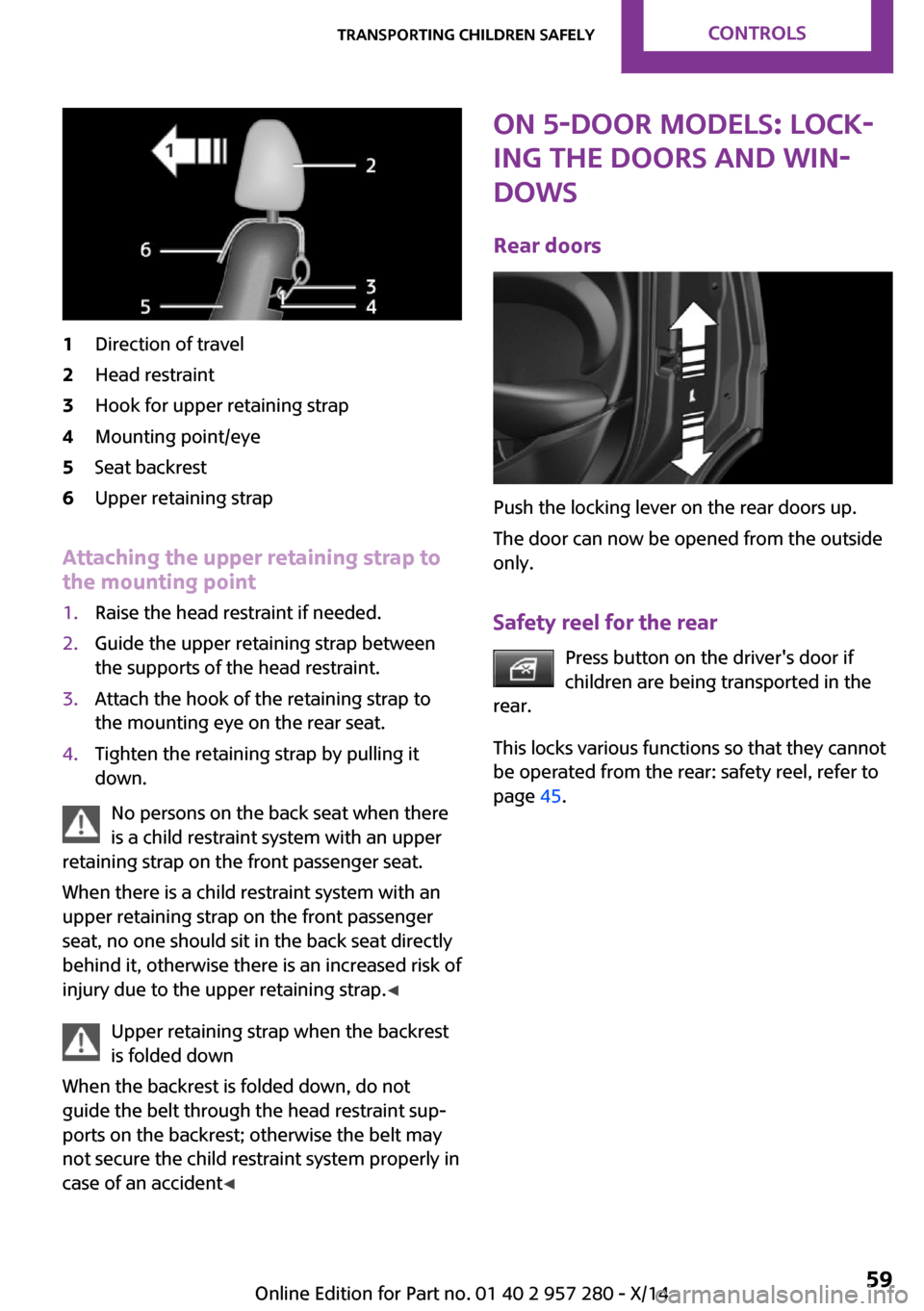
1Direction of travel2Head restraint3Hook for upper retaining strap4Mounting point/eye5Seat backrest6Upper retaining strap
Attaching the upper retaining strap to
the mounting point
1.Raise the head restraint if needed.2.Guide the upper retaining strap between
the supports of the head restraint.3.Attach the hook of the retaining strap to
the mounting eye on the rear seat.4.Tighten the retaining strap by pulling it
down.
No persons on the back seat when there
is a child restraint system with an upper
retaining strap on the front passenger seat.
When there is a child restraint system with an
upper retaining strap on the front passenger
seat, no one should sit in the back seat directly
behind it, otherwise there is an increased risk of
injury due to the upper retaining strap. ◀
Upper retaining strap when the backrest
is folded down
When the backrest is folded down, do not
guide the belt through the head restraint sup‐
ports on the backrest; otherwise the belt may
not secure the child restraint system properly in
case of an accident ◀
ON 5-door models: Lock‐
ing the doors and win‐
dows
Rear doors
Push the locking lever on the rear doors up.
The door can now be opened from the outside
only.
Safety reel for the rear Press button on the driver's door if
children are being transported in the
rear.
This locks various functions so that they cannot
be operated from the rear: safety reel, refer to
page 45.
Seite 59Transporting children safelyCONTROLS59
Online Edition for Part no. 01 40 2 957 280 - X/14
Page 73 of 240
KickdownKickdown is used to achieve maximum driving
performance. Step on the accelerator pedal be‐
yond the resistance point at the full throttle po‐
sition.
Engaging a selector lever position Press on the brake pedal until you start
driving
To prevent the vehicle from creeping after you
select a gear, maintain pressure on the brake
pedal until you are ready to start. ◀
The selector lever can only be taken out of se‐
lector lever position P if the ignition is on or the
engine is running.
With the vehicle is stationary, press on the
brake pedal before shifting out of selector lever
position P or N; otherwise, the selector lever is
blocked: shift lock.
A lock prevents inadvertent shifting into selec‐
tor lever position P or R.
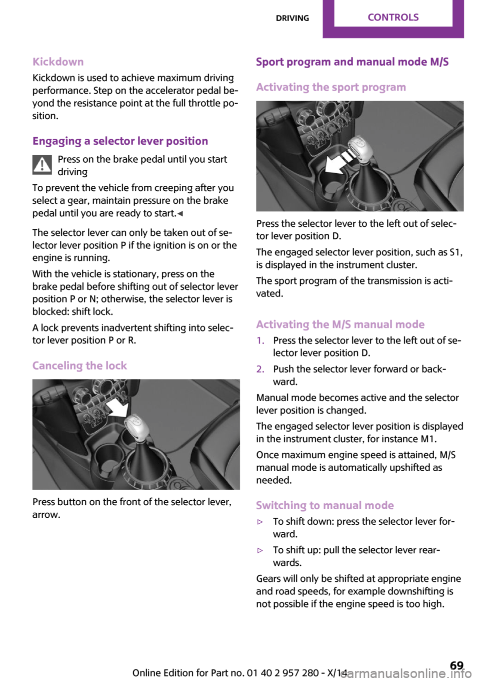
Canceling the lock
Press button on the front of the selector lever,
arrow.
Sport program and manual mode M/S
Activating the sport program
Press the selector lever to the left out of selec‐
tor lever position D.
The engaged selector lever position, such as S1,
is displayed in the instrument cluster.
The sport program of the transmission is acti‐
vated.
Activating the M/S manual mode
1.Press the selector lever to the left out of se‐
lector lever position D.2.Push the selector lever forward or back‐
ward.
Manual mode becomes active and the selector
lever position is changed.
The engaged selector lever position is displayed
in the instrument cluster, for instance M1.
Once maximum engine speed is attained, M/S
manual mode is automatically upshifted as
needed.
Switching to manual mode
▷To shift down: press the selector lever for‐
ward.▷To shift up: pull the selector lever rear‐
wards.
Gears will only be shifted at appropriate engine
and road speeds, for example downshifting is
not possible if the engine speed is too high.
Seite 69DrivingCONTROLS69
Online Edition for Part no. 01 40 2 957 280 - X/14
Page 74 of 240
The selected gear is briefly displayed in the in‐
strument cluster, followed by the currently se‐
lected gear.
Manual mode M/S: prevent automatic
upshifting
Once maximum engine speed is attained, M/S
manual mode is automatically upshifted as
needed.
For vehicles with Steptronic Sport transmission,
automatic shift operations are not performed if
one of the following conditions is met:▷DSC is deactivated.▷TRACTION is activated.
In addition, the kickdown is deactivated.
Ending the sport program/manual
mode
Push the selector lever to the right.
D is displayed in the instrument cluster.
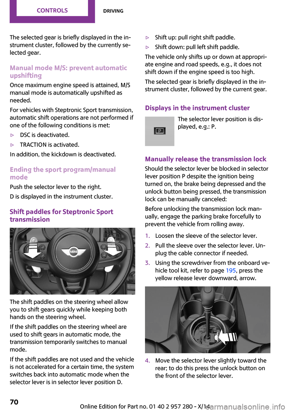
Shift paddles for Steptronic Sport
transmission
The shift paddles on the steering wheel allow
you to shift gears quickly while keeping both
hands on the steering wheel.
If the shift paddles on the steering wheel are
used to shift gears in automatic mode, the
transmission temporarily switches to manual
mode.
If the shift paddles are not used and the vehicle
is not accelerated for a certain time, the system
switches back into automatic mode when the
selector lever is in selector lever position D.
▷Shift up: pull right shift paddle.▷Shift down: pull left shift paddle.
The vehicle only shifts up or down at appropri‐
ate engine and road speeds, e.g., it does not
shift down if the engine speed is too high.
The selected gear is briefly displayed in the in‐
strument cluster, followed by the current gear.
Displays in the instrument cluster The selector lever position is dis‐
played, e.g.: P.
Manually release the transmission lock
Should the selector lever be blocked in selector
lever position P despite the ignition being
turned on, the brake being depressed and the
unlock button being pressed, the transmission
lock can be manually canceled:
Before unlocking the transmission lock man‐
ually, engage the parking brake forcefully to
prevent the vehicle from rolling away.
1.Loosen the sleeve of the selector lever.2.Pull the sleeve over the selector lever. Un‐
plug the cable connector if needed.3.Using the screwdriver from the onboard ve‐
hicle tool kit, refer to page 195, press the
yellow release lever downward, arrow.4.Move the selector lever slightly toward the
rear; to do this press the unlock button on
the front of the selector lever.Seite 70CONTROLSDriving70
Online Edition for Part no. 01 40 2 957 280 - X/14
Page 75 of 240
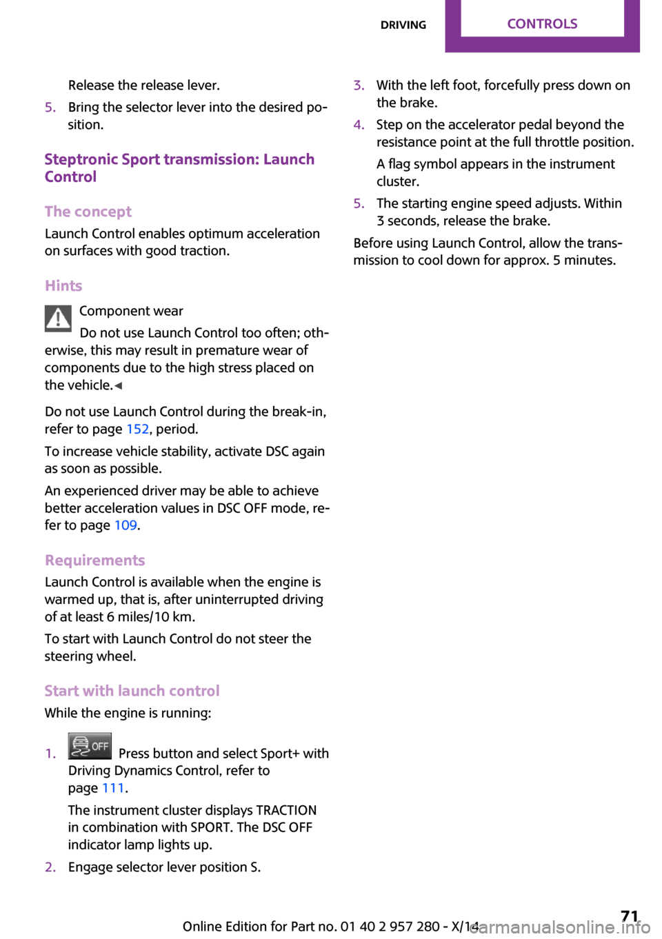
Release the release lever.5.Bring the selector lever into the desired po‐
sition.
Steptronic Sport transmission: Launch
Control
The concept
Launch Control enables optimum acceleration
on surfaces with good traction.
Hints Component wear
Do not use Launch Control too often; oth‐
erwise, this may result in premature wear of
components due to the high stress placed on
the vehicle. ◀
Do not use Launch Control during the break-in,
refer to page 152, period.
To increase vehicle stability, activate DSC again
as soon as possible.
An experienced driver may be able to achieve
better acceleration values in DSC OFF mode, re‐
fer to page 109.
Requirements Launch Control is available when the engine is
warmed up, that is, after uninterrupted driving
of at least 6 miles/10 km.
To start with Launch Control do not steer the
steering wheel.
Start with launch control
While the engine is running:
1. Press button and select Sport+ with
Driving Dynamics Control, refer to
page 111.
The instrument cluster displays TRACTION
in combination with SPORT. The DSC OFF
indicator lamp lights up.2.Engage selector lever position S.3.With the left foot, forcefully press down on
the brake.4.Step on the accelerator pedal beyond the
resistance point at the full throttle position.
A flag symbol appears in the instrument
cluster.5.The starting engine speed adjusts. Within
3 seconds, release the brake.
Before using Launch Control, allow the trans‐
mission to cool down for approx. 5 minutes.
Seite 71DrivingCONTROLS71
Online Edition for Part no. 01 40 2 957 280 - X/14
Page 105 of 240
System limitsSudden tire damage
Sudden serious tire damage caused by
external circumstances cannot be recognized in
advance. ◀
A natural, even tire inflation pressure loss in all
four tires will not be recognized. Therefore,
check the tire inflation pressure regularly.
The system could be delayed or malfunction in
the following situations:▷When the system has not been initialized.▷When driving on a snowy or slippery road
surface.▷Sporty driving style: spinning traction
wheels, high lateral acceleration (drifting).▷When driving with snow chains.
Actions in the event of a flat tire
Normal tires
1.Identify the damaged tire.
Do this by checking the air pressure in all
four tires.
The tire pressure gauge of the Mobility Sys‐
tem, refer to page 181, can be used for this
purpose.
If the tire inflation pressure in all four tires is
correct, the Flat Tire Monitor may not have
been initialized. In this case, initialize the
system.
If an identification is not possible, please
contact the service center.2.Fix the flat tire using the Mobility System,
refer to page 181.
Run-flat tires
Maximum speed
You may continue driving with a damaged tire at speeds up to 50 mph/80 km/h.
Continued driving with a flat tire
If continuing to drive with a damaged tire:1.Avoid sudden braking and steering maneu‐
vers.2.Do not exceed a speed of 50 mph/80 km/h.3.Check the air pressure in all four tires at the
next opportunity.
If the tire inflation pressure in all four tires is
correct, the Flat Tire Monitor may not have
been initialized. In this case, initialize the
system.
Possible driving distance with complete loss of
tire inflation pressure:
The possible driving distance after a loss of tire
inflation pressure depends on cargo load, driv‐
ing style and road conditions.
A vehicle with an average load has a possible
driving range of approx. 50 miles/80 km.
A vehicle with a damaged tire reacts differently,
e.g., it has reduced lane stability during brak‐
ing, a longer braking distance and different
self-steering properties. Adjust your driving
style accordingly. Avoid abrupt steering ma‐
neuvers or driving over obstacles, e.g., curbs,
potholes, etc.
Because the possible driving distance depends
on how the vehicle is used during the trip, the
actual distance may be shorter or longer de‐
pending on the driving speed, road conditions,
external temperature, cargo load, etc.
Continued driving with a flat tire
Drive moderately and do not exceed a
speed of 50 mph/80 km/h.
Your car handles differently when you lose tire
inflation pressure, e.g., your lane stability is re‐
duced when braking, braking distances are lon‐
ger and the self-steering properties will
change. ◀
Seite 101SafetyCONTROLS101
Online Edition for Part no. 01 40 2 957 280 - X/14
Page 114 of 240
The DSC system is switched off.
Activating DSC Press button.
DSC OFF and the DSC OFF indicator
lamp go out.
Indicator/warning lights
When DSC is deactivated, DSC OFF is displayed
in the instrument cluster.
The indicator lamp lights up: DSC is de‐
activated.
Automatic activation When DSC is deactivated, automatic activation
occurs in the following situations:▷Failure of Dynamic Damping Control.▷The vehicle has a flat tire.▷When activating cruise control in TRACTION
or DSC OFF mode.
DTC Dynamic Traction
Control
The concept
The DTC system is a version of the DSC where
forward momentum is optimized.
The system ensures maximum headway on
special road conditions or loose road surfaces,
e.g., unplowed snowy roads, but with some‐
what limited driving stability.
Activating the Dynamic Traction Control DTC
provides maximum traction. Driving stability is
limited during acceleration and when driving in
curves.
Therefore drive with appropriate caution.
You may find it useful to briefly activate DTC
under the following special circumstances:
▷When driving in slush or on uncleared,
snow-covered roads.▷When freeing vehicle from deep snow or
driving off from loose grounds.▷When driving with snow chains.
Deactivating/activating DTC Dynamic
Traction Control
Activating DTC Press button.
TRACTION is displayed in the instru‐
ment cluster and the indicator lamp for DSC
OFF lights up.
Deactivating DTC Press button again.
TRACTION and the DSC OFF indicator
lamp go out.
Performance Control
Performance Control enhances the agility of the
vehicle.
To increase maneuverability, with a corre‐
spondingly sporty driving style, wheels are
braked individually.
Dynamic Damping Con‐
trol
The concept
The tuning of the suspension can be changed
with the system.
Programs
The system offers several different programs.
Select the programs via the Driving Dynamics
Control, refer to page 111.
Seite 110CONTROLSDriving stability control systems110
Online Edition for Part no. 01 40 2 957 280 - X/14