steering MINI 3 door 2015 Owner's Guide
[x] Cancel search | Manufacturer: MINI, Model Year: 2015, Model line: 3 door, Model: MINI 3 door 2015Pages: 248, PDF Size: 5.43 MB
Page 133 of 248

Parking using pathway and turningradius lines1.Position the vehicle so that the turning ra‐
dius lines lead to within the limits of the
parking space.2.Turn the steering wheel to the point where
the pathway line covers the corresponding
turning radius line.
Display settings
Brightness
With the rearview camera switched on:
1. Select the symbol.2.Turn the Controller until the desired setting
is reached and press the Controller.
Contrast
With the rearview camera switched on:
1. Select the symbol.2.Turn the Controller until the desired setting
is reached and press the Controller.System limits
Detection of objects
Very low obstacles or high, protruding objects
such as ledges may not be recognized by the
system.
Assistance functions also take into account data
of the PDC.
Follow instructions in the PDC chapter, refer to
page 128.
The objects displayed on the Control Display
under certain circumstances are closer than
they appear. Therefore, do not estimate the
distance from the objects on the display.
Parking assistant
The concept
This system assists the driver in parking parallel
to the road.
Parking assistant handling is divided into three
steps:
▷Switching on and activating.▷Parking space search.▷Parking.
System status and instructions on required ac‐
tions are displayed on the Control Display.
Ultrasound sensors measure parking spaces on
both sides of the vehicle.
The parking assistant calculates the best possi‐
ble parking line and takes control of steering
during the parking procedure.
Seite 133Driving comfortCONTROLS133
Online Edition for Part no. 01 40 2 964 625 - X/15
Page 135 of 248
▷When parking in parking spaces on the
driver's side, the corresponding turn signal
must be set.
Switching on and activating
Switching on with the button Press button.
The LED lights up.
The current status of the parking space search
is indicated on the Control Display.
Parking assistant is activated automatically.
Switching on with reverse gear
Shift into reverse.
The current status of the parking space search
is indicated on the Control Display.
To activate:
"Parking Assistant"
Indicator on the Control Display
System activated/deactivated
SymbolMeaning Gray: the system is not available.
White: the system is available but not
activated. The system is activated.
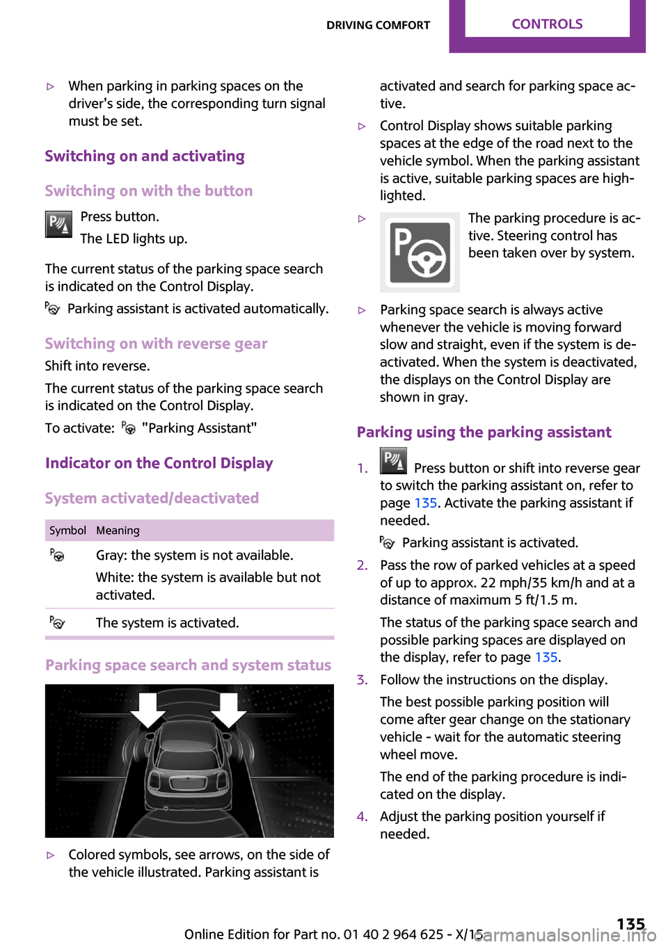
Parking space search and system status
▷Colored symbols, see arrows, on the side of
the vehicle illustrated. Parking assistant isactivated and search for parking space ac‐
tive.▷Control Display shows suitable parking
spaces at the edge of the road next to the
vehicle symbol. When the parking assistant
is active, suitable parking spaces are high‐
lighted.▷The parking procedure is ac‐
tive. Steering control has
been taken over by system.▷Parking space search is always active
whenever the vehicle is moving forward
slow and straight, even if the system is de‐
activated. When the system is deactivated,
the displays on the Control Display are
shown in gray.
Parking using the parking assistant
1. Press button or shift into reverse gear
to switch the parking assistant on, refer to
page 135. Activate the parking assistant if
needed.
Parking assistant is activated.
2.Pass the row of parked vehicles at a speed
of up to approx. 22 mph/35 km/h and at a
distance of maximum 5 ft/1.5 m.
The status of the parking space search and
possible parking spaces are displayed on
the display, refer to page 135.3.Follow the instructions on the display.
The best possible parking position will
come after gear change on the stationary
vehicle - wait for the automatic steering
wheel move.
The end of the parking procedure is indi‐
cated on the display.4.Adjust the parking position yourself if
needed.Seite 135Driving comfortCONTROLS135
Online Edition for Part no. 01 40 2 964 625 - X/15
Page 136 of 248

Interrupting manuallyThe parking assistant can be interrupted at any
time:▷ "Parking Assistant"▷Press button.
Interrupting automatically
The system is interrupted automatically in the
following situations:
▷If the driver grasps the steering wheel or if
he takes over steering.▷If a gear is selected that does not match the
instruction on the display.▷If the vehicle speed exceeds approx.
6 mph/10 km/h.▷Possible on snow-covered or slippery road
surfaces.▷If a maximum number of parking attempts
or the time taken for parking is exceeded.▷If the Park Distance Control PDC displays
clearances that are too small.▷When switching into other functions of the
radio.
A Check Control message is displayed.
Resume
An interrupted parking procedure can be con‐
tinued if needed.
Reactivate the parking assistant, refer to page 135, and follow the instructions on the
display.
Switching off The system can be deactivated as follows:
▷Press button.▷Switching off the ignition.System limits
Information WARNING
The system can react incorrectly or not at
all due to the system limits. There is risk of acci‐
dents or risk of property damage. Observe the
system limits and actively interfere if needed. ◀
No parking assistance The parking assistant does not offer assistance
in the following situations:▷In tight curves.
Functional limitations
The system may not be fully functional in the
following situations:
▷On bumpy road surfaces such as gravel
roads.▷On slippery ground.▷With accumulations of leaves/snow in the
parking space.▷With a mounted emergency wheel.▷With ditches or edges, for example an edge
of a port.
Limits of ultrasonic measurement
Ultrasonic measuring might not function under
the following circumstances:
▷For small children and animals.▷For persons with certain clothing, for exam‐
ple coats.▷With external interference of the ultra‐
sound, for example from passing vehicles
or loud machines.▷When sensors are dirty, iced over, damaged
or out of position.▷If cargo protrudes.▷Under certain weather conditions such as
high relative humidity, rain, snowfall, ex‐
treme heat or strong wind.Seite 136CONTROLSDriving comfort136
Online Edition for Part no. 01 40 2 964 625 - X/15
Page 147 of 248

4.Likewise, press and hold the button of the
desired function on the hand-held trans‐
mitter.5.Release both buttons as soon as the interior
rearview mirror LED flashes more rapidly.
The LED flashing faster indicates that the
button on the interior rearview mirror has
been programmed. The system can then be
controlled by the button on the interior
rearview mirror.
If the LED does not flash faster after at least
60 seconds, change the distance and re‐
peat the step. Several more attempts at dif‐
ferent distances may be necessary. Wait at
least 15 seconds between attempts.
Canada: if programming with the hand-
held transmitter was interrupted, hold
down the interior rearview mirror button
and repeatedly press and release the hand-
held transmitter button for 2 seconds.
Controls
WARNING
Body parts can be jammed when operat‐
ing remote-controlled systems, for example the
garage door, using the integrated universal re‐
mote control. There is risk of injuries or risk of
property damage. Make sure that the area of
movement of the respective system is clear
during programming and operation. Also follow
the safety instructions of the hand-held trans‐
mitter. ◀
The system, such as the garage door, can be
operated using the button on the interior rear‐
view mirror while the engine is running or
when the ignition is started. To do this, hold
down the button within receiving range of the
system until the function is activated. The inte‐
rior rearview mirror LED stays lit while the wire‐
less signal is being transmitted.
Deleting stored functions
Press and hold the left and right button on the
interior rearview mirror simultaneously for ap‐
proximately 20 seconds until the LED flashes
rapidly. All stored functions will be deleted. The
functions cannot be deleted individually.
Digital compass
Overview1Control button2Mirror display
Mirror display The point of the compass is displayed in the
mirror when driving straight.
Operating concept Various functions can be called up by pressing
the control button with a pointed object, such
as the tip of a ballpoint pen or similar object.
The following setting options are displayed in
succession, depending on how long the control
button is pressed:
▷Pressed briefly: turns display on/off.▷3 to 6 seconds: compass zone setting.▷6 to 9 seconds: compass calibration.▷9 to 12 seconds: left/right-hand steering
setting.▷12 to 15 seconds: language setting.
Setting the compass zones
Sets the particular compass zones on the vehi‐
cle so that the compass operates correctly; re‐
fer to World map with compass zones.
Seite 147Interior equipmentCONTROLS147
Online Edition for Part no. 01 40 2 964 625 - X/15
Page 148 of 248
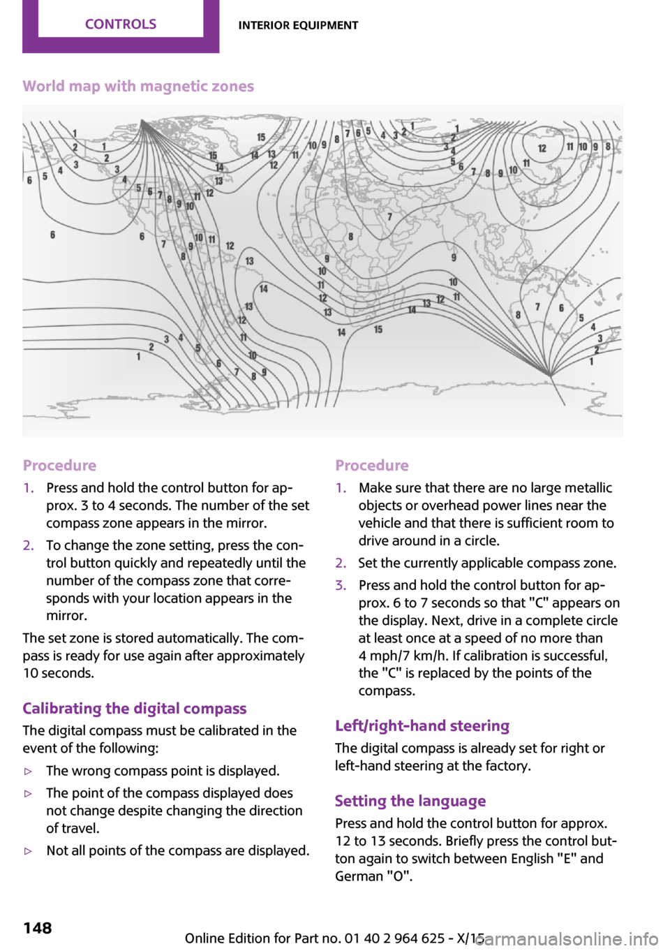
World map with magnetic zonesProcedure1.Press and hold the control button for ap‐
prox. 3 to 4 seconds. The number of the set
compass zone appears in the mirror.2.To change the zone setting, press the con‐
trol button quickly and repeatedly until the
number of the compass zone that corre‐
sponds with your location appears in the
mirror.
The set zone is stored automatically. The com‐
pass is ready for use again after approximately
10 seconds.
Calibrating the digital compass The digital compass must be calibrated in the
event of the following:
▷The wrong compass point is displayed.▷The point of the compass displayed does
not change despite changing the direction
of travel.▷Not all points of the compass are displayed.Procedure1.Make sure that there are no large metallic
objects or overhead power lines near the
vehicle and that there is sufficient room to
drive around in a circle.2.Set the currently applicable compass zone.3.Press and hold the control button for ap‐
prox. 6 to 7 seconds so that "C" appears on
the display. Next, drive in a complete circle
at least once at a speed of no more than
4 mph/7 km/h. If calibration is successful,
the "C" is replaced by the points of the
compass.
Left/right-hand steering
The digital compass is already set for right or
left-hand steering at the factory.
Setting the language
Press and hold the control button for approx.
12 to 13 seconds. Briefly press the control but‐ ton again to switch between English "E" and
German "O".
Seite 148CONTROLSInterior equipment148
Online Edition for Part no. 01 40 2 964 625 - X/15
Page 161 of 248
General driving notes
Closing the tailgate WARNING
An open tailgate protrudes from the vehi‐
cle and can endanger occupants and other traf‐
fic participants or damage the vehicle in the
event of an accident, braking or evasive ma‐
neuvers. In addition, exhaust fumes may enter
the vehicle interior. There is risk of injuries or
risk of property damage. Do not drive with the
tailgate open. ◀
If driving with the tailgate open cannot be
avoided:▷Close all windows and the glass sunroof.▷Greatly increase the air flow from the vents.▷Drive moderately.
Hot exhaust system
WARNING
During driving operation, high tempera‐
tures can occur underneath the body, for ex‐
ample caused by the exhaust gas system. If
combustible materials, such as leaves or grass,
come in contact with hot parts of the exhaust
gas system, these materials can ignite. There is
risk of injuries or risk of property damage.
Do not remove the heat shields installed and
never apply undercoating to them. Make sure
that no combustible materials can come in con‐
tact with hot vehicle parts in driving operation,
idle or during parking. Do not touch the hot ex‐
haust system. ◀
Mobile communication devices in the vehicle
WARNING
Vehicle electronics and mobile phones
can influence one another. There is radiation
due to the send operations of mobile phones.
There is risk of injuries or risk of property dam‐
age. If possible, in the car's interior use only
mobile phones with direct connections to an
exterior antenna in order to exclude mutual
disturbance and deflect the radiation from the
car's interior. ◀
Hydroplaning On wet or slushy roads, a wedge of water can
form between the tires and road surface.
This phenomenon is referred to as hydroplan‐
ing. It is characterized by a partial or complete
loss of contact between the tires and the road
surface, ultimately undermining your ability to
steer and brake the vehicle.
Driving through water CAUTION
When driving too quickly through too
deep water, water can enter into the engine compartment, the electrical system or the
transmission. There is risk of property damage.
When driving through water, do not exceed the
maximum indicated water level and the maxi‐
mum speed for driving through water. ◀
When driving through water, observe the fol‐
lowing:▷Drive through calm water only.▷Drive through water only if it is not deeper
than maximum 9.8 inches/25 cm.▷Drive through water no faster than walking
speed, up to 3 mph/5 km/h.
Braking safely
Your vehicle is equipped with ABS as a standard
feature.
Perform an emergency stop in situations that require such.
Steering is still responsive. You can still avoid
any obstacles with a minimum of steering ef‐
fort.
Pulsation of the brake pedal and sounds from
the hydraulic circuits indicate that ABS is in its
active mode.
Seite 161Things to remember when drivingDRIVING TIPS161
Online Edition for Part no. 01 40 2 964 625 - X/15
Page 162 of 248
Objects in the area around the pedalsWARNING
Objects in the driver's floor area can limit
the pedal distance or block a depressed pedal.
There is risk of an accident. Stow objects in the
vehicle such that they are secured and cannot
enter into the driver's floor area. Use floor mats
that are suitable for the vehicle and can be
safely attached to the floor. Do not use loose
floor mats and do not layer several floor mats.
Make sure that there is sufficient clearance for
the pedals. Ensure that the floor mats are se‐
curely fastened again after they were removed,
for example for cleaning. ◀
Driving in wet conditions When roads are wet, salted, or in heavy rain,
press brake pedal ever so gently every few
miles.
Ensure that this action does not endanger other
traffic.
The heat generated in this process helps dry
the brake discs and pads.
In this way braking efficiency will be available
when you need it.
Hills WARNING
Light but consistent brake pressure can
lead to high temperatures, brakes wearing out
and possibly even brake failure. There is risk of
an accident. Avoid placing excessive stress on
the brake system. ◀
WARNING
In idle or with the engine switched off,
safety-relevant functions are restricted or not
available anymore, for example braking effect
of the engine or braking force and steering
support. There is risk of an accident. Do not
drive in idle or with the engine switched off. ◀
Drive long or steep downhill gradients in the
gear that requires least braking efforts. Other‐wise the brakes may overheat and reduce
brake efficiency.
You can increase the engine's braking effect by
shifting down, going all the way to first gear, if
needed.
Brake disc corrosion Corrosion on the brake discs and contamina‐
tion on the brake pads are furthered by:▷Low mileage.▷Extended periods when the vehicle is not
used at all.▷Infrequent use of the brakes.
Corrosion will built up when the maximum
pressure applied to the brake pads during brak‐
ing is not reached - thus discs don't get
cleaned.
Corrosion buildup on the brake discs will cause
a pulsating effect on the brakes in their re‐
sponse - generally that cannot be corrected.
Condensation under the parked vehicle When using the automatic climate control, con‐
densation water develops collecting under‐
neath the vehicle.
Ground clearance CAUTION
If ground clearance is insufficient, there
might be contact with the front or rear spoiler
for example when driving over curbs or enter‐
ing into underground car parking garages.
There is risk of property damage. Ensure that
there is sufficient ground clearance available. ◀
Seite 162DRIVING TIPSThings to remember when driving162
Online Edition for Part no. 01 40 2 964 625 - X/15
Page 165 of 248
Roof racks are available as special accessories.Securing
Follow the installation instructions of the roof
rack.
Loading
Because roof racks raise the vehicle's center of
gravity when loaded, they have a major effect
on vehicle handling and steering response.
Therefore, note the following when loading and
driving:▷Do not exceed the approved roof/axle
loads and the approved gross vehicle
weight.▷Be sure that adequate clearance is main‐
tained for tilting and opening the glass sun‐
roof.▷Distribute the roof load uniformly.▷The roof load should not extend past the
loading area.▷Always place the heaviest pieces on the
bottom.▷Secure the roof luggage firmly, e.g., tie with
ratchet straps.▷Do not let objects project into the opening
path of the tailgate.▷Drive cautiously and avoid sudden acceler‐
ation and braking maneuvers. Take corners
gently.
Rear luggage rack
General information Installation only possible with rear luggage rack
preparation.
Rear racks are available as special accessories.
Information Follow the installation instructions of the rear
luggage rack.
Drive cautiously and avoid sudden acceleration
and braking maneuvers. Take corners gently.
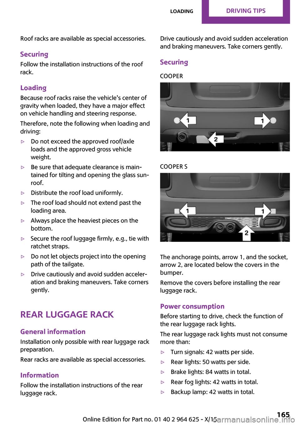
SecuringCOOPERCOOPER S
The anchorage points, arrow 1, and the socket,
arrow 2, are located below the covers in the
bumper.
Remove the covers before installing the rear
luggage rack.
Power consumption
Before starting to drive, check the function of
the rear luggage rack lights.
The rear luggage rack lights must not consume
more than:
▷Turn signals: 42 watts per side.▷Rear lights: 50 watts per side.▷Brake lights: 84 watts in total.▷Rear fog lights: 42 watts in total.▷Backup lamp: 42 watts in total.Seite 165LoadingDRIVING TIPS165
Online Edition for Part no. 01 40 2 964 625 - X/15
Page 180 of 248
Wheels and tiresVehicle features and op‐
tions
This chapter describes all standard, country-
specific and optional features offered with the
series. It also describes features that are not
necessarily available in your car, e. g., due to
the selected options or country versions. This
also applies to safety-related functions and sys‐
tems. The respectively applicable country provi‐
sions must be observed when using the respec‐
tive features and systems.
Tire inflation pressure Safety informationThe tire characteristics and tire inflation pres‐
sure influence the following:▷The service life of the tires.▷Road safety.▷Driving comfort.
Checking the tire inflation pressure
WARNING
A tire with low or missing tire inflation
pressure impacts handling, such as steering
and braking response. There is risk of an acci‐
dent. Regularly check the tire inflation pressure,
and correct it as needed, for example twice a
month and before a long trip. ◀
Tires have a natural, consistent loss of tire infla‐
tion pressure.
Tires heat up while driving, and the tire inflation
pressure increases along with the tire's temper‐
ature. The tire inflation pressure specifications
relate to cold tires or tires with the ambient
temperature.
Only check the tire inflation pressure when the
tires are cold. This means after driving no more
than 1.25 miles/2 km or when the vehicle has
been parked for at least 2 hours.
The displays of inflation devices may under-
read by up to 0.1 bar.
For Flat Tire Monitor: after correcting the tire
inflation pressure, reinitialize the Flat Tire Moni‐
tor.
For Tire Pressure Monitor: after correcting the
tire inflation pressure, reset the Tire Pressure
Monitor.▷Reinitialize the Flat Tire Monitor.▷Reinitialize the Tire Pressure Monitor.
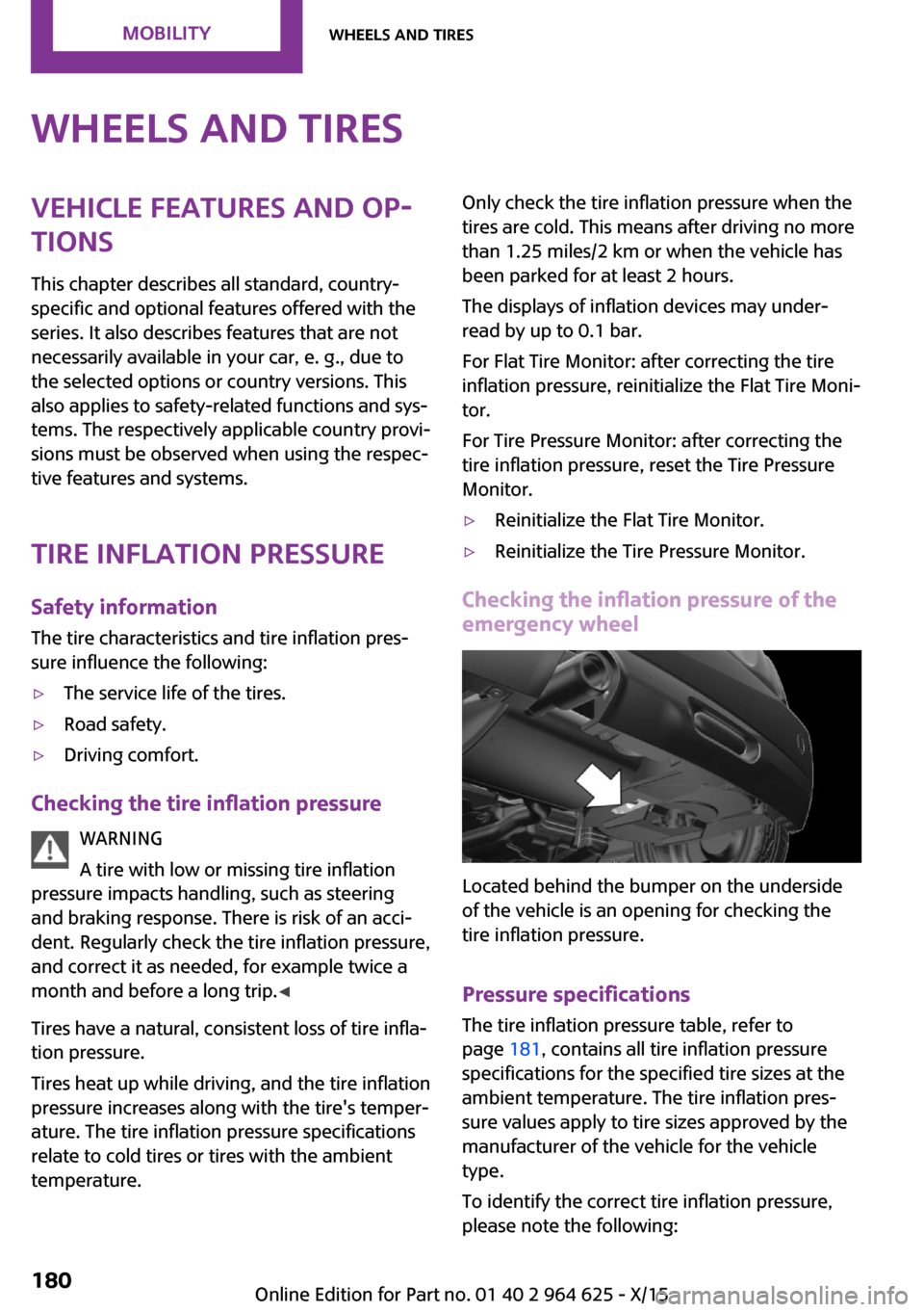
Checking the inflation pressure of the
emergency wheel
Located behind the bumper on the underside
of the vehicle is an opening for checking the
tire inflation pressure.
Pressure specifications
The tire inflation pressure table, refer to
page 181, contains all tire inflation pressure
specifications for the specified tire sizes at the
ambient temperature. The tire inflation pres‐
sure values apply to tire sizes approved by the
manufacturer of the vehicle for the vehicle
type.
To identify the correct tire inflation pressure,
please note the following:
Seite 180MOBILITYWheels and tires180
Online Edition for Part no. 01 40 2 964 625 - X/15
Page 190 of 248
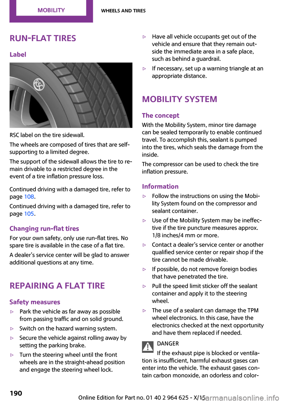
Run-flat tiresLabel
RSC label on the tire sidewall.
The wheels are composed of tires that are self-
supporting to a limited degree.
The support of the sidewall allows the tire to re‐
main drivable to a restricted degree in the
event of a tire inflation pressure loss.
Continued driving with a damaged tire, refer to
page 108.
Continued driving with a damaged tire, refer to
page 105.
Changing run-flat tires
For your own safety, only use run-flat tires. No
spare tire is available in the case of a flat tire.
A dealer’s service center will be glad to answer additional questions at any time.
Repairing a flat tireSafety measures
▷Park the vehicle as far away as possible
from passing traffic and on solid ground.▷Switch on the hazard warning system.▷Secure the vehicle against rolling away by
setting the parking brake.▷Turn the steering wheel until the front
wheels are in the straight-ahead position
and engage the steering wheel lock.▷Have all vehicle occupants get out of the
vehicle and ensure that they remain out‐
side the immediate area in a safe place,
such as behind a guardrail.▷If necessary, set up a warning triangle at an
appropriate distance.
Mobility System
The concept
With the Mobility System, minor tire damage
can be sealed temporarily to enable continued
travel. To accomplish this, sealant is pumped
into the tires, which seals the damage from the
inside.
The compressor can be used to check the tire
inflation pressure.
Information
▷Follow the instructions on using the Mobi‐
lity System found on the compressor and
sealant container.▷Use of the Mobility System may be ineffec‐
tive if the tire puncture measures approx.
1/8 inches/4 mm or more.▷Contact a dealer’s service center or another
qualified service center or repair shop if the
tire cannot be made drivable.▷If possible, do not remove foreign bodies
that have penetrated the tire.▷Pull the speed limit sticker off the sealant
container and apply it to the steering
wheel.▷The use of a sealant can damage the TPM
wheel electronics. In this case, have the
electronics checked at the next opportunity
and have them replaced if needed.
DANGER
If the exhaust pipe is blocked or ventila‐
tion is insufficient, harmful exhaust gases can
enter into the vehicle. The exhaust gases con‐
tain carbon monoxide, an odorless and color‐
Seite 190MOBILITYWheels and tires190
Online Edition for Part no. 01 40 2 964 625 - X/15