check engine light MINI Clubman 2010 Owner's Manual (Mini Connected)
[x] Cancel search | Manufacturer: MINI, Model Year: 2010, Model line: Clubman, Model: MINI Clubman 2010Pages: 218, PDF Size: 3.97 MB
Page 15 of 218
MOBILITYAT A GLANCE CONTROLS DRIVING TIPS ENTERTAINMENT
13
NAVIGATION REFERENCE
Indicator and warning
lamps
The concept
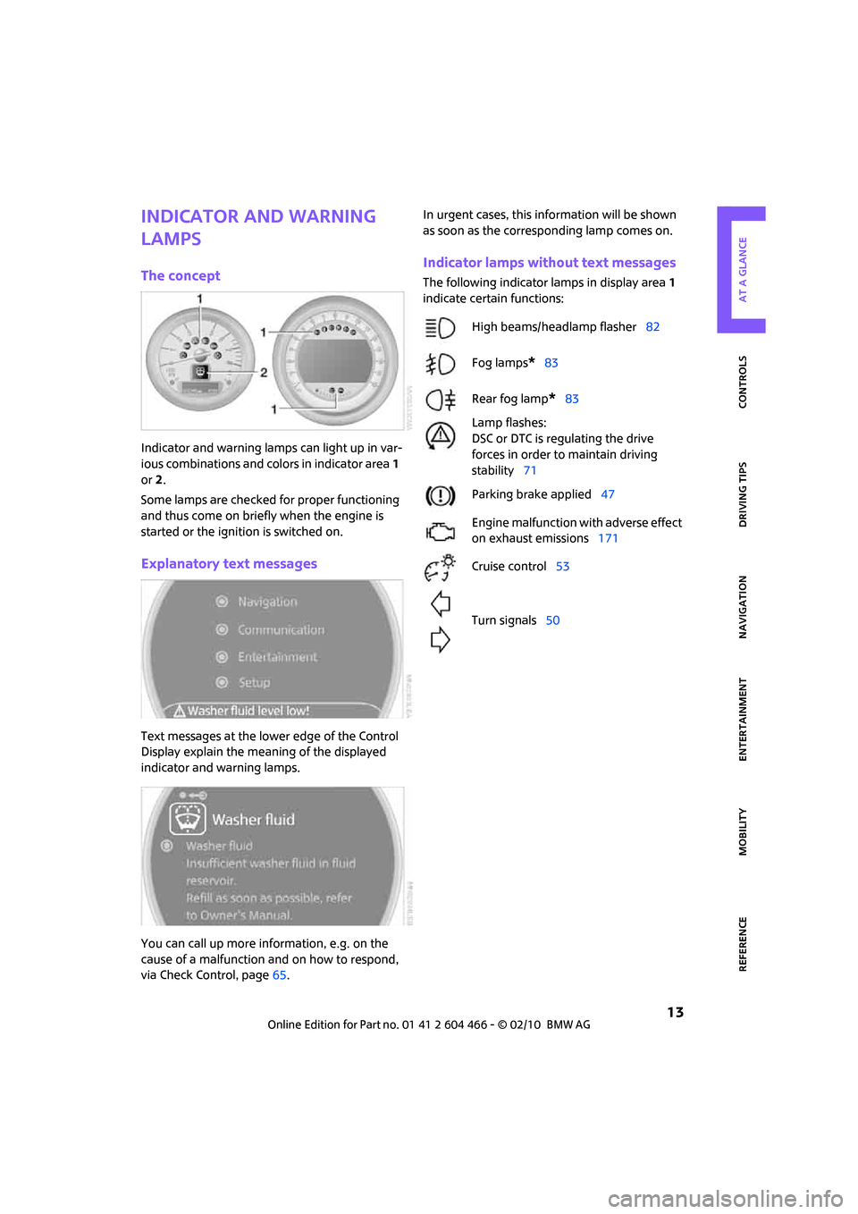
Indicator and warning lamps can light up in var-
ious combinations and colors in indicator area 1
or2.
Some lamps are checked for proper functioning
and thus come on briefly when the engine is
started or the ignition is switched on.
Explanatory text messages
Text messages at the lower edge of the Control
Display explain the meaning of the displayed
indicator and warning lamps.
You can call up more information, e.g. on the
cause of a malfunction and on how to respond,
via Check Control, page65.In urgent cases, this information will be shown
as soon as the corresponding lamp comes on.
Indicator lamps without text messages
The following indicator lamps in display area 1
indicate certain functions:
High beams/headlamp flasher82
Fog lamps
*83
Rear fog lamp
*83
Lamp flashes:
DSC or DTC is regulating the drive
forces in order to maintain driving
stability71
Parking brake applied47
Engine malfunction with adverse effect
on exhaust emissions171
Cruise control53
Turn signals50
Page 35 of 218
MOBILITYAT A GLANCE CONTROLS DRIVING TIPS ENTERTAINMENT
33
NAVIGATION REFERENCE
Comfort Access*
Comfort Access enables you to enter your vehi-
cle without having to hold the remote control in
your hand. All you need to do is wear the remote
control close to your body, e.g. in your jacket
pocket. The vehicle automatically detects the
remote control within the immediate vicinity or
in the passenger compartment.
Functional requirements
>The vehicle or the splitdoor can only be
locked when the vehicle detects that the
remote control currently in use is outside of
the vehicle.
>The vehicle cannot be locked or unlocked
again until after approx. 2 seconds.
>The engine can only be started when the
vehicle detects that the remote control is
inside the vehicle.
>The doors and splitdoor must be closed to be
able to operate the windows and glass sun-
roof
*.
Comfort Access supports the following func-
tions:
>Unlocking/locking the vehicle
>Unlocking the splitdoor by itself
>Starting the engine
Comparison to standard remote controls
Essentially, it makes no difference whether you
control the above-mentioned functions using
Comfort Access or by pressing the buttons on
the remote control for Comfort Access.
Instructions on opening and closing are found
starting on page26.
Special features regarding the use of Comfort
Access are described below.
If you notice a brief delay while opening or
closing the windows or glass sunroof, the
system is checking whether a remote control is
inside the vehicle. Repeat the opening or closing
procedure, if necessary.<
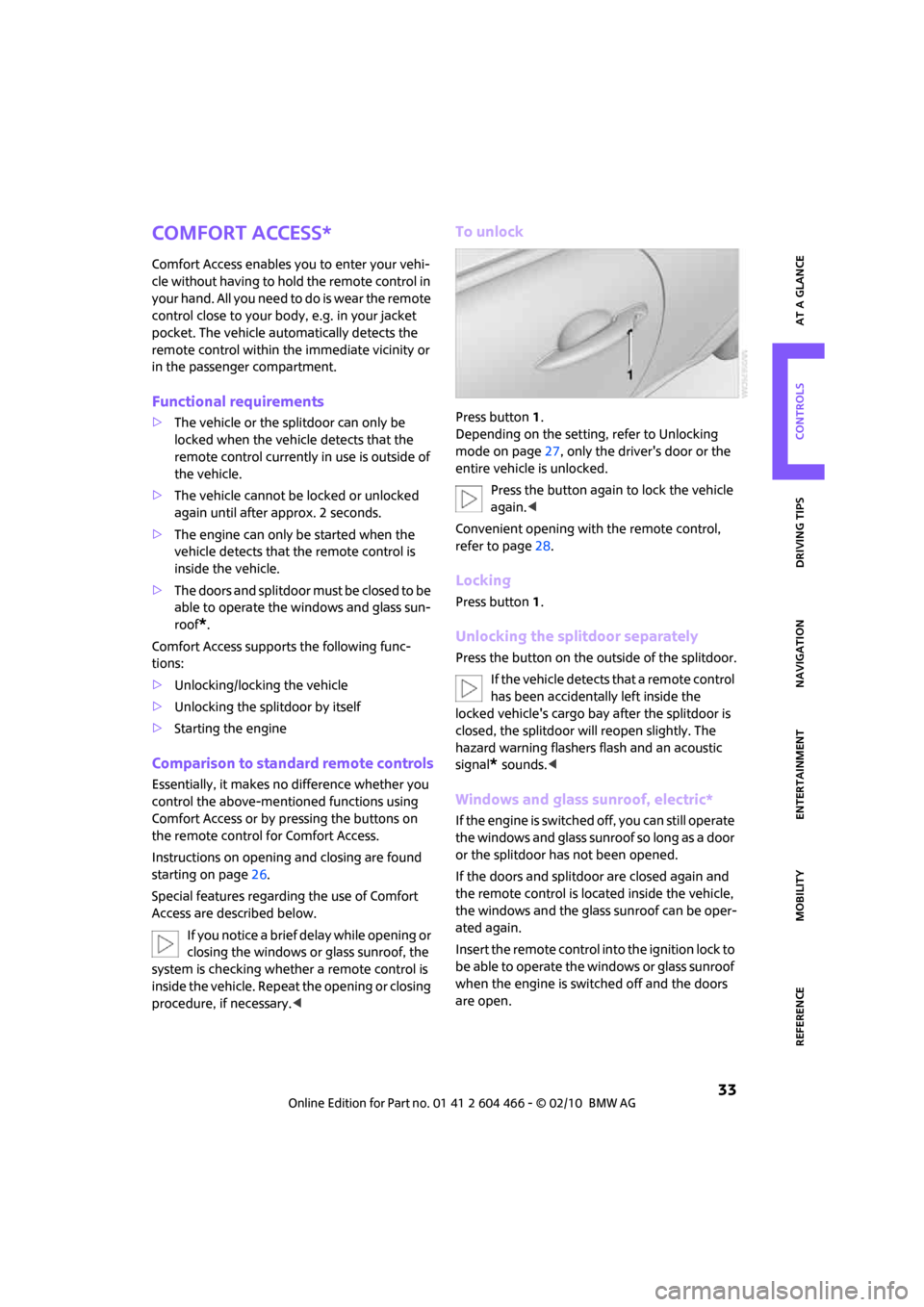
To unlock
Press button 1.
Depending on the setting, refer to Unlocking
mode on page27, only the driver's door or the
entire vehicle is unlocked.
Press the button again to lock the vehicle
again.<
Convenient opening with the remote control,
refer to page28.
Locking
Press button 1.
Unlocking the splitdoor separately
Press the button on the outside of the splitdoor.
If the vehicle detects that a remote control
has been accidentally left inside the
locked vehicle's cargo bay after the splitdoor is
closed, the splitdoor will reopen slightly. The
hazard warning flashers flash and an acoustic
signal
* sounds.<
Windows and glass sunroof, electric*
If the engine is switched off, you can still operate
the windows and glass sunroof so long as a door
or the splitdoor has not been opened.
If the doors and splitdoor are closed again and
the remote control is located inside the vehicle,
the windows and the glass sunroof can be oper-
ated again.
Insert the remote control into the ignition lock to
be able to operate the windows or glass sunroof
when the engine is switched off and the doors
are open.
Page 58 of 218
Controls overview
56
Coolant temperature
A warning lamp will come on if the coolant, and
therefore the engine, becomes too hot. In addi-
tion, a message will appear on the Control Dis-
play.
Check coolant level, refer to page169.
Fuel gauge
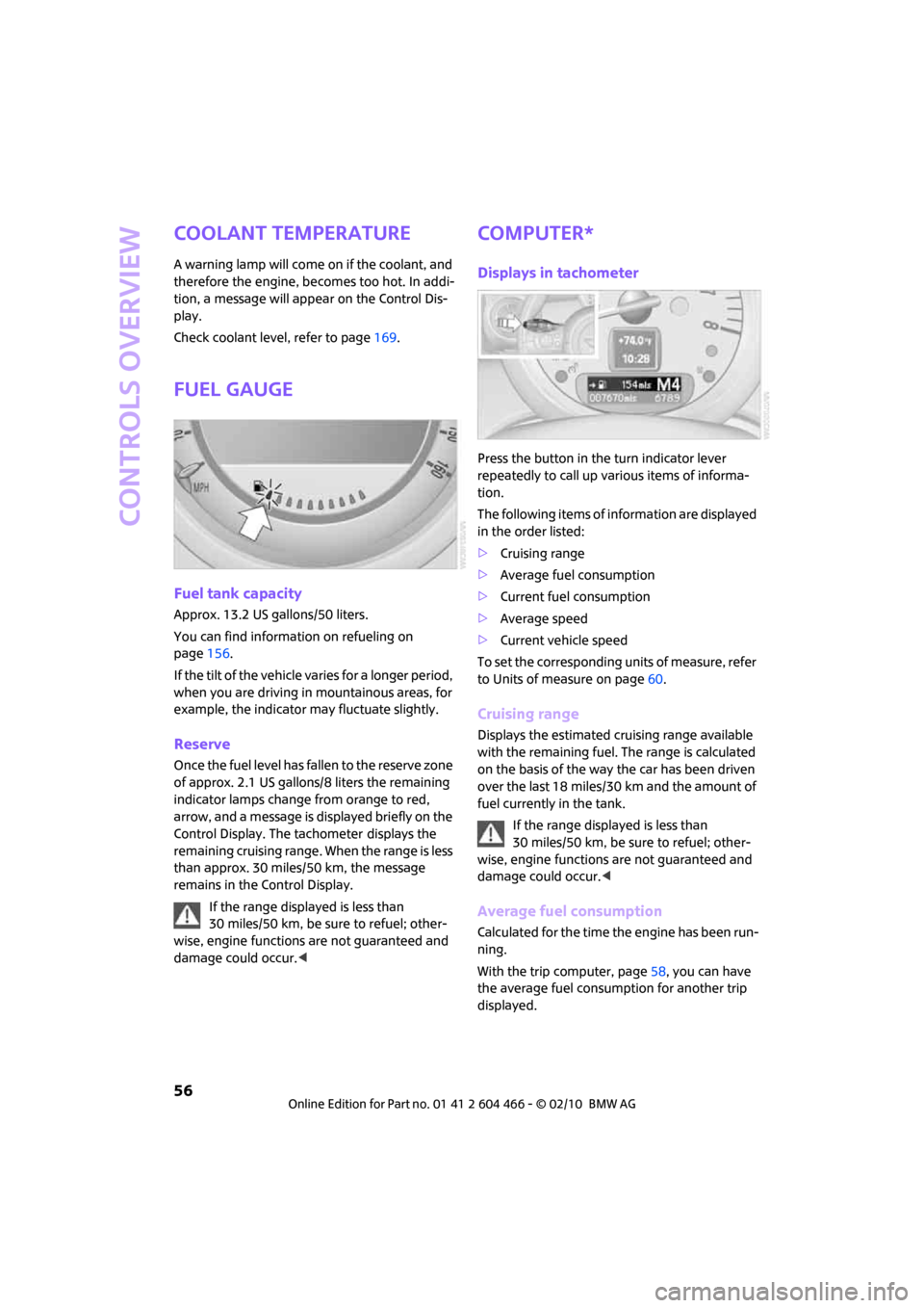
Fuel tank capacity
Approx. 13.2 US gallons/50 liters.
You can find information on refueling on
page156.
If the tilt of the vehicle varies for a longer period,
when you are driving in mountainous areas, for
example, the indicator may fluctuate slightly.
Reserve
Once the fuel level has fallen to the reserve zone
of approx. 2.1 US gallons/8 liters the remaining
indicator lamps change from orange to red,
arrow, and a message is displayed briefly on the
Control Display. The tachometer
displays the
remaining cruising range. When the range is less
than approx. 30 miles/50 km, the message
remains in the Control Display.
If the range displayed is less than
30 miles/50 km, be sure to refuel; other-
wise, engine functions are not guaranteed and
damage could occur.<
Computer*
Displays in tachometer
Press the button in the turn indicator lever
repeatedly to call up various items of informa-
tion.
The following items of information are displayed
in the order listed:
>Cruising range
>Average fuel consumption
>Current fuel consumption
>Average speed
>Current vehicle speed
To set the corresponding units of measure, refer
to Units of measure on page60.
Cruising range
Displays the estimated cruising range available
with the remaining fuel. The range is calculated
on the basis of the way the car has been driven
over the last 18 miles/30 km and the amount of
fuel currently in the tank.
If the range displayed is less than
30 miles/50 km, be sure to refuel; other-
wise, engine functions are not guaranteed and
damage could occur.<
Average fuel consumption
Calculated for the time the engine has been run-
ning.
With the trip computer, page58, you can have
the average fuel consumption for another trip
displayed.
Page 63 of 218
MOBILITYAT A GLANCE CONTROLS DRIVING TIPS ENTERTAINMENT
61
NAVIGATION REFERENCE
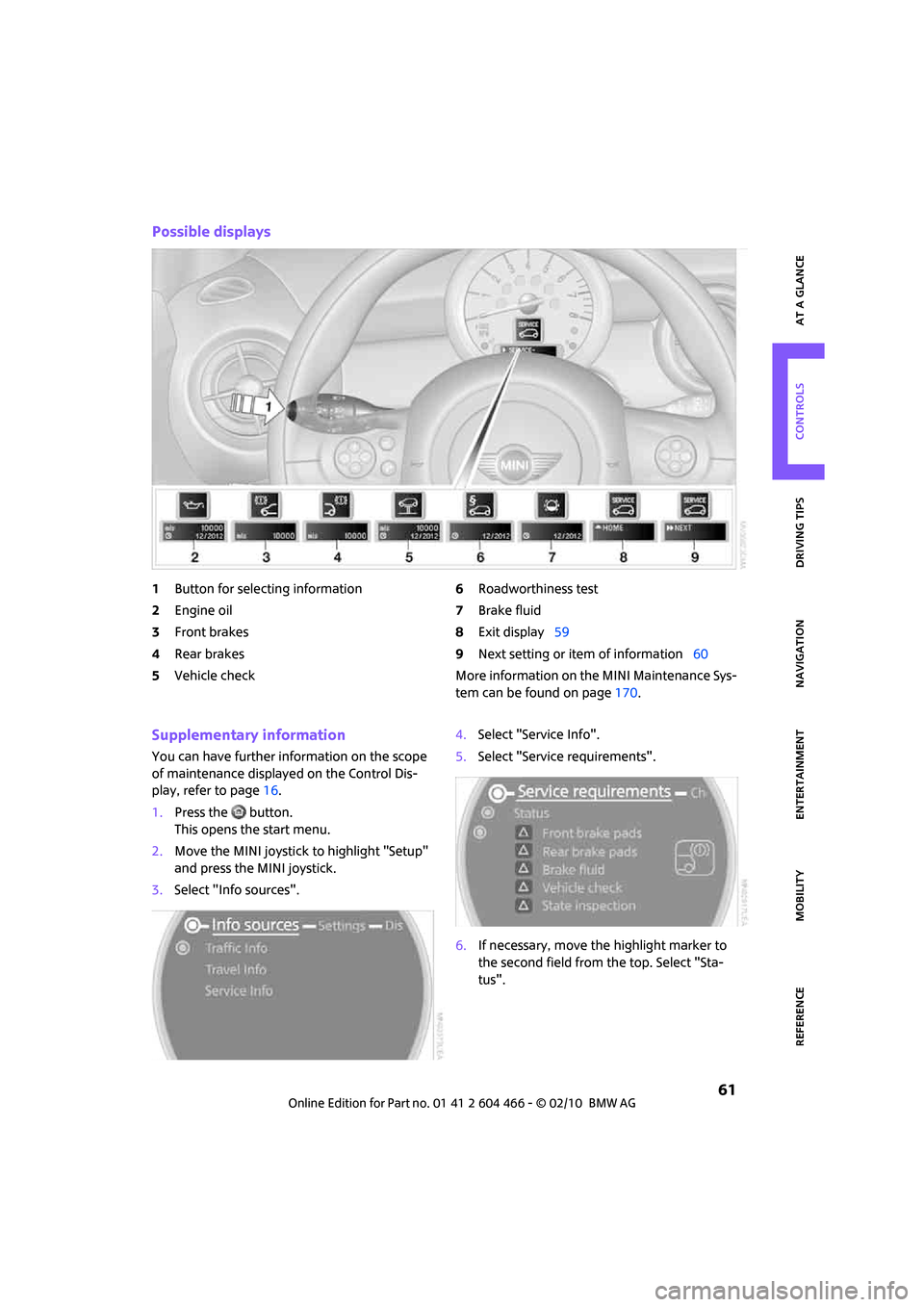
Possible displays
1Button for selecting information
2Engine oil
3Front brakes
4Rear brakes
5Vehicle check6Roadworthiness test
7Brake fluid
8Exit display59
9Next setting or item of information60
More information on the MINI Maintenance Sys-
tem can be found on page170.
Supplementary information
You can have further information on the scope
of maintenance displayed on the Control Dis-
play, refer to page16.
1.Press the button.
This opens the start menu.
2.Move the MINI joystick to highlight "Setup"
and press the MINI joystick.
3.Select "Info sources".4.Select "Service Info".
5.Select "Service requirements".
6.If necessary, move the highlight marker to
the second field from the top. Select "Sta-
tus".
Page 72 of 218
Technology for driving comfort and safety
70
Technology for driving comfort and
safety
Park Distance Control
PDC*
The concept
PDC assists you with parking backwards. Acous-
tic signals and a visual indicator
warn you of the
presence of an object behind the vehicle. To
measure the distance, there are four ultrasonic
sensors in either bumper.
These sensors have a range of approx.
6.5 ft/2 m. However, an acoustic warning
does not sound until an object is approx. 24 in/
60 cm from the rear corner sensors, or approx.
5 ft/1.50 m from the rear center sensors. PDC is
a parking aid that can indicate objects when
they are approached slowly, as is usually the
case when parking. Avoid approaching an
object at high speed; otherwise, physical cir-
cumstances may lead to the system warning
being issued too late.<
Automatic mode
With the engine running or the ignition switched
on, the system is activated automatically after
approx. 1 second when you engage reverse gear
or move the automatic transmission selector
lever to position R. Wait this short period before
driving.
Acoustic signals
As the distance between vehicle and object
decreases, the intervals between the tones
become shorter. If the distance to the nearest
object falls to below roughly 1 ft/30 cm, then a
continuous tone sounds.
If the distance remains constant, e.g. when driv-
ing parallel to a wall, the acoustic signal stops
after approx. 3 seconds.
Malfunction
Indicator lamp comes on: PDC has
failed. A message appears on the Con-
trol Display. Have the system checked.
To avoid this problem, keep the sensors clean
and free of ice or snow in order to ensure that
they will continue to operate effectively. When
using a high-pressure cleaner, do not direct the
jet toward the sensors for lengthy periods and
only spray from a distance of at least 4 in/10 cm.
PDC with visual warning
To have the system show distances to objects on
the Control Display. The contours of distant
objects are shown on the Control Display even
before the acoustic signal sounds.
Onboard monitor, for operating principle refer
to page16.
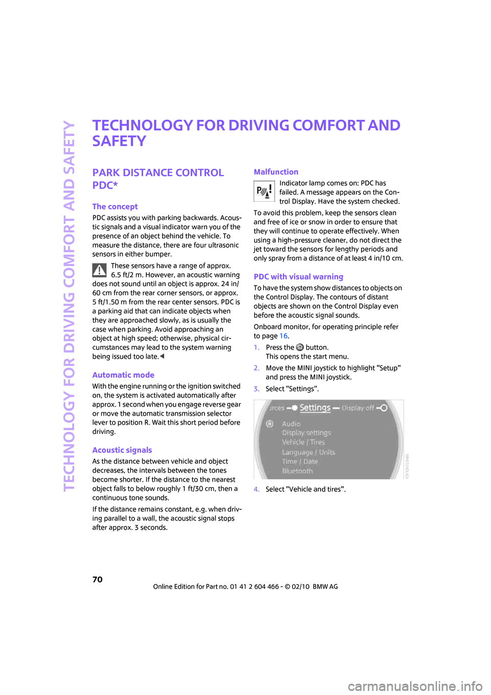
1.Press the button.
This opens the start menu.
2.Move the MINI joystick to highlight "Setup"
and press the MINI joystick.
3.Select "Settings".
4.Select "Vehicle and tires".
Page 91 of 218
MOBILITYAT A GLANCE CONTROLS DRIVING TIPS ENTERTAINMENT
89
NAVIGATION REFERENCE
The corresponding memory button 1 is now
programmed with the signal of the original
hand-held transmitter.
You can operate the system with the engine
running or with the ignition switched on.
If the system fails to function even after
repeated programming, check whether
the original hand-held transmitter uses an alter-
nating-code system. To do so, either read the
instructions for the original hand-held transmit-
ter or hold down the programmed memory
button1 of the integrated universal remote con-
trol. If the LED2 on the integrated universal
remote control flashes rapidly and then remains
lit for about two seconds, the original hand-held
transmitter uses an alternating-code system. If it
uses an alternating-code system, program the
memory buttons1 as described under Alternat-
ing-code hand-held transmitters.<
Alternating-code hand-held
transmitters
To program the integrated universal remote
control, consult the operating instructions for
the device to be set. You will find information
there on the possibilities for synchronization or
programming of additional hand-held transmit-
ters.
When programming hand-held transmitters that
employ an alternating code, please observe the
following supplementary instructions:
Programming will be easier with the aid of
a second person.<
1.Park your vehicle within the range of the
remote-controlled device.
2.Program the integrated universal remote
control as described above in the section
Fixed-code hand-held transmitters.
3.Locate the button on the receiver of the
device to be set, e.g. on the drive unit.
4.Press the button on the receiver of the
device to be set. After step 4, you have
approx. 30 seconds for the next step 5.
5.Press the programmed memory button1 of
the integrated universal remote control
three times.The corresponding memory button 1 is now
programmed with the signal of the original
hand-held transmitter.
Clearing stored programs
Press both outer memory buttons1 for approx.
20 seconds until the LED2 flashes: all stored
programs are cleared.
It is not possible to clear individual programs.
Reassigning individual programs
1.Hold the original hand-held transmitter at a
distance of approx. 2 in to 12 in/5 to 30 cm
from the memory buttons1.
The required distance between the
hand-held transmitter and the mem-
ory buttons1 depends on the system of the
respective original hand-held transmitter
used.<
2.Press the desired memory button1 of the
integrated universal remote control.
3.If the LED 2 flashes slowly after approx.
20 seconds, press the transmit key of the
original hand-held transmitter and release
both buttons as soon as the LED2 flashes
rapidly.
If the LED 2 does not flash rapidly after
approx. 15 seconds, alter the distance and
repeat this step.
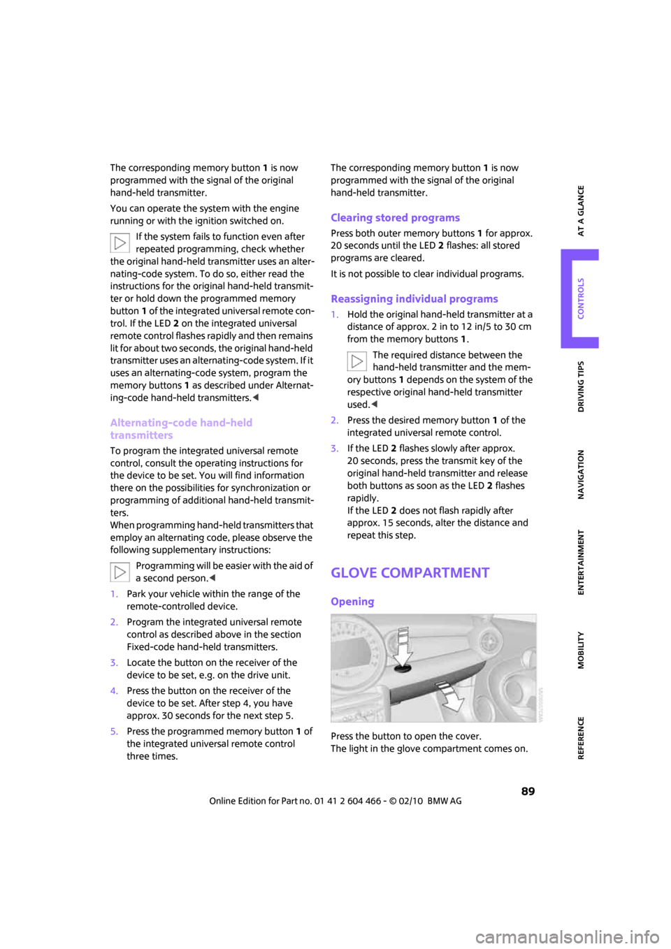
Glove compartment
Opening
Press the button to open the cover.
The light in the glove compartment comes on.
Page 173 of 218
MOBILITYAT A GLANCE CONTROLS DRIVING TIPS ENTERTAINMENT
171
NAVIGATION REFERENCE
Emissions
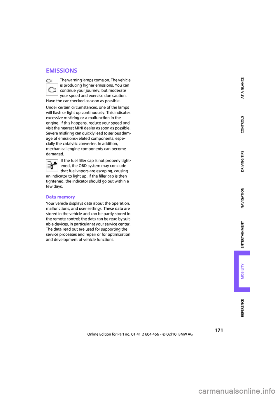
The warning lamps come on. The vehicle
is producing higher emissions. You can
continue your journey, but moderate
your speed and exercise due caution.
Have the car checked as soon as possible.
Under certain circumstances, one of the lamps
will flash or light up continuously. This indicates
excessive misfiring or a malfunction in the
engine. If this happens, reduce your speed and
visit the nearest MINI dealer as soon as possible.
Severe misfiring can quickly lead to serious dam-
age of emissions-related components, espe-
cially the catalytic converter. In addition,
mechanical engine components can become
damaged.
If the fuel filler cap is not properly tight-
ened, the OBD system may conclude
that fuel vapors are escaping, causing
an indicator to light up. If the filler cap is then
tightened, the indicator should go out within a
few days.
Data memory
Your vehicle displays data about the operation,
malfunctions, and user settings. These data are
stored in the vehicle and can be partly stored in
the remote control; the data can be read by suit-
able devices, in particular at your service center.
The data read out are used for supporting the
service processes and repair or for optimization
and development of vehicle functions.
Page 179 of 218
MOBILITYAT A GLANCE CONTROLS DRIVING TIPS ENTERTAINMENT
177
NAVIGATION REFERENCE
When working on electrical systems,
always begin by switching off the con-
sumer in question; otherwise, short circuits
could result. To avoid possible injury or equip-
ment damage when replacing bulbs, observe
any instructions provided by the bulb manufac-
turer.<
Caring for headlamps, refer to page173.
For any bulb replacement not described
below, contact a MINI dealer or a work-
shop that has specially trained personnel work-
ing in accordance with the specifications of the
MINI manufacturer.<
For checking and adjusting headlamp aim,
please contact your MINI dealer.<
Light-emitting diodes LEDs
Light-emitting diodes installed behind translu-
cent lenses serve as the light sources for many of
the controls and displays in your vehicle. These
light-emitting diodes are related to conven-
tional laser diodes, and legislation defines them
as Class 1 light-emitting diodes.
Do not remove the covers or expose the
eyes directly to the unfiltered light source
for several hours; otherwise, this could cause
irritation of the retina.<
Headlight glass lens
In cool or humid weather, condensation may
occur on the interior of outside lights. The con-
densation disappears a short time after the light
is switched on. Headlight glass lenses do not
need to be replaced. If a lot of moisture is
present, e.g. water droplets in the light, have
them checked by your service center.
Xenon lamps*
The service life of these bulbs is very long and
the probability of failure very low, provided that
they are not switched on and off an excessive
number of times. If a xenon lamp fails neverthe-
less, switch on the fog lamps and continue the
journey with great care, provided that local leg-
islation does not prohibit this.Have any work on the xenon lamp system,
including bulb replacement, carried out
only by a MINI dealer or a workshop that has
specially trained personnel working in accor-
dance with the specifications of the MINI manu-
facturer. Due to high voltage, there is a risk of
fatal injury if work on the xenon lamps is carried
out improperly.<
Halogen low beams and high beams
H13 bulb, 60/55 watts
The H13 bulb is pressurized. Therefore,
wear safety glasses and protective gloves.
Otherwise, there is a risk of injury if the bulb is
damaged.<
Be careful when installing the cover; oth-
erwise, leaks could occur and cause dam-
age to the headlamp system.<
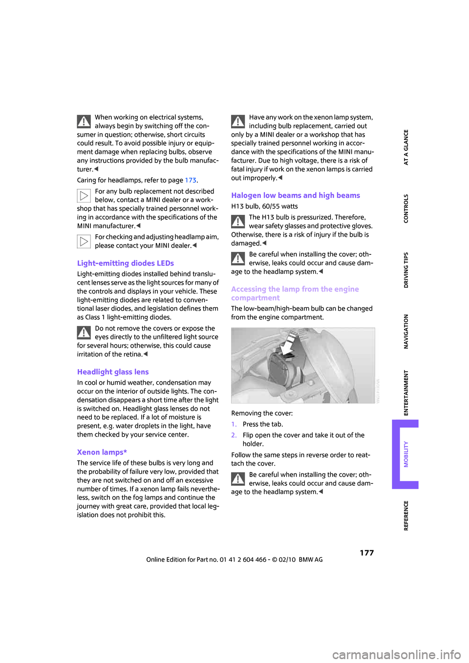
Accessing the lamp from the engine
compartment
The low-beam/high-beam bulb can be changed
from the engine compartment.
Removing the cover:
1.Press the tab.
2.Flip open the cover and take it out of the
holder.
Follow the same steps in reverse order to reat-
tach the cover.
Be careful when installing the cover; oth-
erwise, leaks could occur and cause dam-
age to the headlamp system.<
Page 184 of 218
Replacing components
182
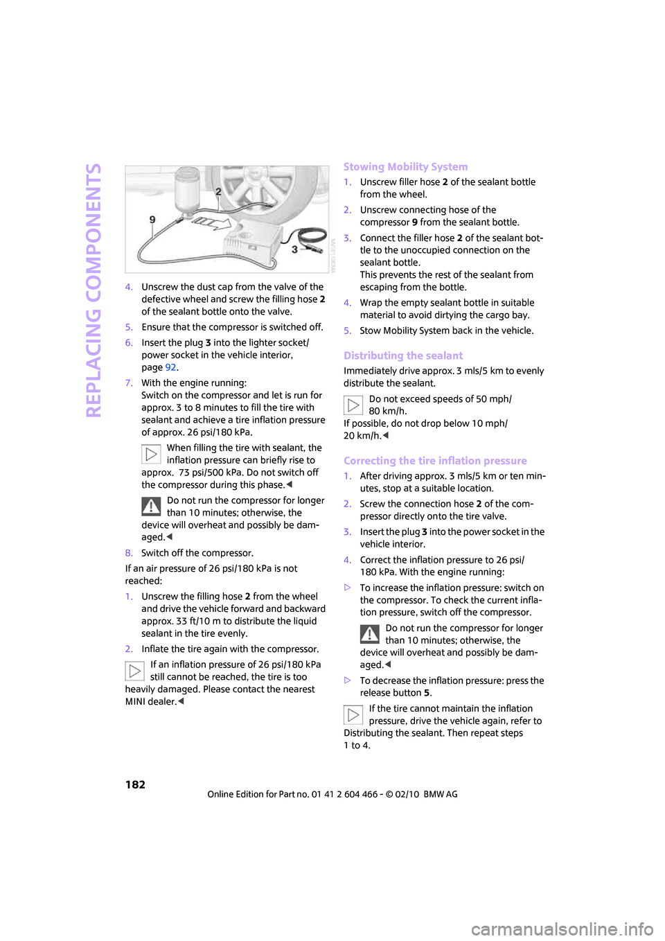
4.Unscrew the dust cap from the valve of the
defective wheel and screw the filling hose 2
of the sealant bottle onto the valve.
5.Ensure that the compressor is switched off.
6.Insert the plug 3 into the lighter socket/
power socket in the vehicle interior,
page92.
7.With the engine running:
Switch on the compressor and let is run for
approx. 3 to 8 minutes to fill the tire with
sealant and achieve a tire inflation pressure
of approx. 26 psi/180 kPa.
When filling the tire with sealant, the
inflation pressure can briefly rise to
approx. 73 psi/500 kPa. Do not switch off
the compressor during this phase.<
Do not run the compressor for longer
than 10 minutes; otherwise, the
device will overheat and possibly be dam-
aged.<
8.Switch off the compressor.
If an air pressure of 26 psi/180 kPa is not
reached:
1.Unscrew the filling hose 2 from the wheel
and drive the vehicle forward and backward
approx. 33 ft/10 m to distribute the liquid
sealant in the tire evenly.
2.Inflate the tire again with the compressor.
If an inflation pressure of 26 psi/180 kPa
still cannot be reached, the tire is too
heavily damaged. Please contact the nearest
MINI dealer.<
Stowing Mobility System
1.Unscrew filler hose2 of the sealant bottle
from the wheel.
2.Unscrew connecting hose of the
compressor9 from the sealant bottle.
3.Connect the filler hose2 of the sealant bot-
tle to the unoccupied connection on the
sealant bottle.
This prevents the rest of the sealant from
escaping from the bottle.
4.Wrap the empty sealant bottle in suitable
material to avoid dirtying the cargo bay.
5.Stow Mobility System back in the vehicle.
Distributing the sealant
Immediately drive approx. 3 mls/5 km to evenly
distribute the sealant.
Do not exceed speeds of 50 mph/
80 km/h.
If possible, do not drop below 10 mph/
20 km/h.<
Correcting the tire inflation pressure
1.After driving approx. 3 mls/5 km or ten min-
utes, stop at a suitable location.
2.Screw the connection hose 2 of the com-
pressor directly onto the tire valve.
3.Insert the plug 3 into the power socket in the
vehicle interior.
4.Correct the inflation pressure to 26 psi/
180 kPa. With the engine running:
>To increase the inflation pressure: switch on
the compressor. To check the current infla-
tion pressure, switch off the compressor.
Do not run the compressor for longer
than 10 minutes; otherwise, the
device will overheat and possibly be dam-
aged.<
>To decrease the inflation pressure: press the
release button5.
If the tire cannot maintain the inflation
pressure, drive the vehicle again, refer to
Distributing the sealant. Then repeat steps
1to4.
Page 189 of 218
MOBILITYAT A GLANCE CONTROLS DRIVING TIPS ENTERTAINMENT
187
NAVIGATION REFERENCE
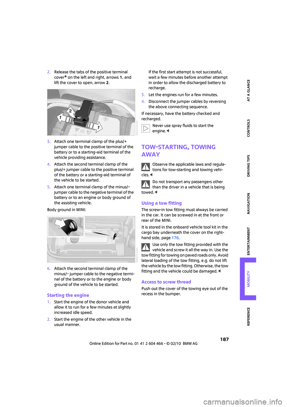
2.Release the tabs of the positive terminal
cover
* on the left and right, arrows1, and
lift the cover to open, arrow2.
3.Attach one terminal clamp of the plus/+
jumper cable to the positive terminal of the
battery or to a starting-aid terminal of the
vehicle providing assistance.
4.Attach the second terminal clamp of the
plus/+ jumper cable to the positive terminal
of the battery or a starting-aid terminal of
the vehicle to be started.
5.Attach one terminal clamp of the minus/–
jumper cable to the negative terminal of the
battery or to an engine or body ground of
the assisting vehicle.
Body ground in MINI:
6.Attach the second terminal clamp of the
minus/– jumper cable to the negative termi-
nal of the battery or to the engine or body
ground of the vehicle to be started.
Starting the engine
1.Start the engine of the donor vehicle and
allow it to run for a few minutes at slightly
increased idle speed.
2.Start the engine of the other vehicle in the
usual manner. If the first start attempt is not successful,
wait a few minutes before another attempt
in order to allow the discharged battery to
recharge.
3.Let the engines run for a few minutes.
4.Disconnect the jumper cables by reversing
the above connecting sequence.
If necessary, have the battery checked and
recharged.
Never use spray fluids to start the
engine.<
Tow-starting, towing
away
Observe the applicable laws and regula-
tions for tow-starting and towing vehi-
cles.<
Do not transport any passengers other
than the driver in a vehicle that is being
towed.<
Using a tow fitting
The screw-in tow fitting must always be carried
in the car. It can be screwed in at the front or
rear of the MINI.
It is stored in the onboard vehicle tool kit in the
cargo bay underneath the cover on the right-
hand side, page176.
Use only the tow fitting provided with the
vehicle and screw it all the way in. Use the
tow fitting for towing on paved roads only. Avoid
lateral loading of the tow fitting, e.g. do not lift
the vehicle by the tow fitting. Otherwise, the tow
fitting and the vehicle could be damaged.<
Access to screw thread
Push out the cover of the towing eye out of the
recess in the bumper.