lock MINI Clubman 2010 Owner's Guide
[x] Cancel search | Manufacturer: MINI, Model Year: 2010, Model line: Clubman, Model: MINI Clubman 2010Pages: 160, PDF Size: 2.58 MB
Page 44 of 160
Driving
42
Applying
The lever locks in position automatically.
Releasing
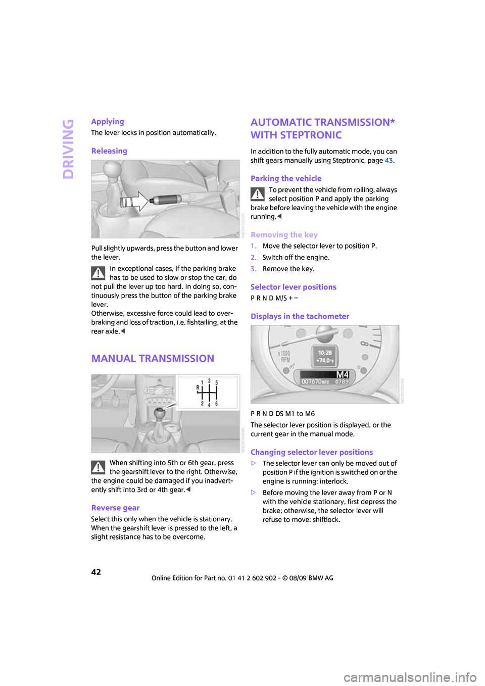
Pull slightly upwards, press the button and lower
the lever.
In exceptional cases, if the parking brake
has to be used to slow or stop the car, do
not pull the lever up too hard. In doing so, con-
tinuously press the button of the parking brake
lever.
Otherwise, excessive force could lead to over-
braking and loss of traction, i.e. fishtailing, at the
rear axle.<
Manual transmission
When shifting into 5th or 6th gear, press
the gearshift lever to the right. Otherwise,
the engine could be damaged if you inadvert-
ently shift into 3rd or 4th gear.<
Reverse gear
Select this only when the vehicle is stationary.
When the gearshift lever is pressed to the left, a
slight resistance has to be overcome.
Automatic transmission*
with Steptronic
In addition to the fully automatic mode, you can
shift gears manually using Steptronic, page43.
Parking the vehicle
To prevent the vehicle from rolling, always
select position P and apply the parking
brake before leaving the vehicle with the engine
running.<
Removing the key
1.Move the selector lever to position P.
2.Switch off the engine.
3.Remove the key.
Selector lever positions
P R N D M/S + –
Displays in the tachometer
P R N D DS M1 to M6
The selector lever position is displayed, or the
current gear in the manual mode.
Changing selector lever positions
>The selector lever can only be moved out of
position P if the ignition is switched on or the
engine is running: interlock.
>Before moving the lever away from P or N
with the vehicle stationary, first depress the
brake; otherwise, the selector lever will
refuse to move: shiftlock.
Page 45 of 160
REFERENCEAT A GLANCE CONTROLS DRIVING TIPS MOBILITY
43
To prevent the vehicle from creeping
after you select a driving position,
depress the brake until you are ready to
start.<
A lock prevents accidental shifting into selector
lever positions R and P.
Overriding the selector lever lock
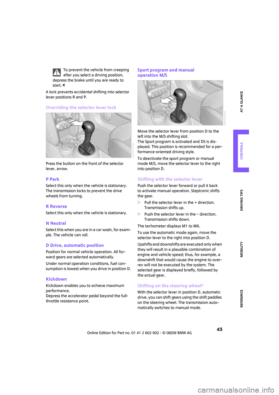
Press the button on the front of the selector
lever, arrow.
P Park
Select this only when the vehicle is stationary.
The transmission locks to prevent the drive
wheels from turning.
R Reverse
Select this only when the vehicle is stationary.
N Neutral
Select this when you are in a car wash, for exam-
ple. The vehicle can roll.
D Drive, automatic position
Position for normal vehicle operation. All for-
ward gears are selected automatically.
Under normal operation conditions, fuel con-
sumption is lowest when you drive in position D.
Kickdown
Kickdown enables you to achieve maximum
performance.
Depress the accelerator pedal beyond the full-
throttle resistance point.
Sport program and manual
operation M/S
Move the selector lever from position D to the
left into the M/S shifting slot:
The Sport program is activated and DS is dis-
played. This position is recommended for a per-
formance-oriented driving style.
To deactivate the sport program or manual
mode M/S, move the selector lever to the right
into position D.
Shifting with the selector lever
Push the selector lever forward or pull it back
to activate manual operation. Steptronic shifts
the gear.
>Pull the selector lever in the + direction.
Transmission shifts up.
>Push the selector lever in the – direction.
Transmission shifts down.
The tachometer displays M1 to M6.
To use the automatic mode again, move the
selector lever to the right into position D.
Upshifts and downshifts are executed only when
they will result in a plausible combination of
engine and vehicle speed; thus, for example, a
downshift that would cause the engine to over-
rev will not be executed by the system. The
selected gear is displayed briefly, followed by
the actual gear.
Shifting on the steering wheel*
With the selector lever in position D, automatic
drive, you can shift gears using the shift paddles
on the steering wheel. The transmission auto-
matically switches to manual mode.
Page 46 of 160
Driving
44
If you do not shift gears with the shift paddles or
accelerate for a certain amount of time, the
transmission automatically returns to D, auto-
matic drive.
>Pull one of the shift paddles.
Transmission shifts up.
>Push one of the shift paddles.
Transmission shifts down.
M1 to M6 is displayed in the gear indicator.
Manually unlock the selector lever lock
Should the selector lever refuse to move out of
position P even though the ignition is switched
on, the brake is depressed and the button on the
selector lever is pressed, the selector lever lock
can be overridden:
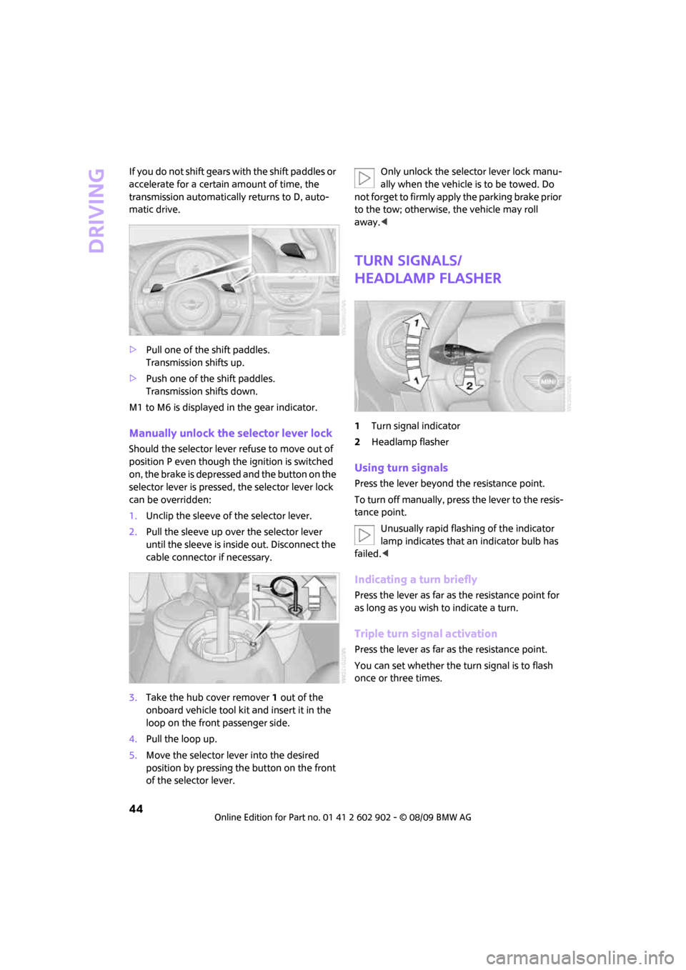
1.Unclip the sleeve of the selector lever.
2.Pull the sleeve up over the selector lever
until the sleeve is inside out. Disconnect the
cable connector if necessary.
3.Take the hub cover remover1 out of the
onboard vehicle tool kit and insert it in the
loop on the front passenger side.
4.Pull the loop up.
5.Move the selector lever into the desired
position by pressing the button on the front
of the selector lever.Only unlock the selector lever lock manu-
ally when the vehicle is to be towed. Do
not forget to firmly apply the parking brake prior
to the tow; otherwise, the vehicle may roll
away.<
Turn signals/
headlamp flasher
1Turn signal indicator
2Headlamp flasher
Using turn signals
Press the lever beyond the resistance point.
To turn off manually, press the lever to the resis-
tance point.
Unusually rapid flashing of the indicator
lamp indicates that an indicator bulb has
failed.<
Indicating a turn briefly
Press the lever as far as the resistance point for
as long as you wish to indicate a turn.
Triple turn signal activation
Press the lever as far as the resistance point.
You can set whether the turn signal is to flash
once or three times.
Page 51 of 160
REFERENCEAT A GLANCE CONTROLS DRIVING TIPS MOBILITY
49
Controls overview
Odometer, outside
temperature display,
clock
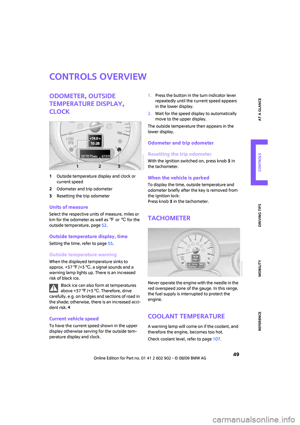
1Outside temperature display and clock or
current speed
2Odometer and trip odometer
3Resetting the trip odometer
Units of measure
Select the respective units of measure, miles or
km for the odometer as well as 7 or 6 for the
outside temperature, page52.
Outside temperature display, time
Setting the time, refer to page55.
Outside temperature warning
When the displayed temperature sinks to
approx. +377/+36, a signal sounds and a
warning lamp lights up. There is an increased
risk of black ice.
Black ice can also form at temperatures
above +377/+36. Therefore, drive
carefully, e.g. on bridges and sections of road in
the shade; otherwise, there is an increased acci-
dent risk.<
Current vehicle speed
To have the current speed shown in the upper
display otherwise serving for the outside tem-
perature display and clock.1.Press the button in the turn indicator lever
repeatedly until the current speed appears
in the lower display.
2.Wait for the speed display to automatically
move to the upper display.
The outside temperature then appears in the
lower display.
Odometer and trip odometer
Resetting the trip odometer
With the ignition switched on, press knob 3 in
the tachometer.
When the vehicle is parked
To display the time, outside temperature and
odometer briefly after the key is removed from
the ignition lock:
Press knob 3 in the tachometer.
Tachometer
Never operate the engine with the needle in the
red overspeed zone of the gauge. In this range,
the fuel supply is interrupted to protect the
engine.
Coolant temperature
A warning lamp will come on if the coolant, and
therefore the engine, becomes too hot.
Check coolant level, refer to page107.
Page 53 of 160
REFERENCEAT A GLANCE CONTROLS DRIVING TIPS MOBILITY
51
Current vehicle speed
To have the current speed shown in the upper
display otherwise serving for the outside tem-
perature display and clock.1.Press the button in the turn indicator lever
repeatedly until the current speed appears
in the lower display.
2.Wait for the speed display to automatically
move to the upper display.
The outside temperature then appears in the
lower display of the computer.
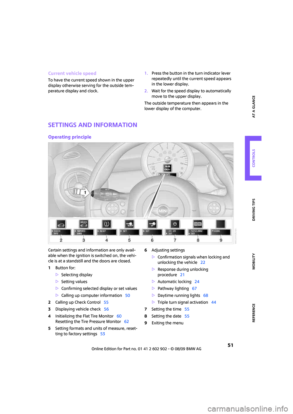
Settings and information
Operating principle
Certain settings and information are only avail-
able when the ignition is switched on, the vehi-
cle is at a standstill and the doors are closed.
1Button for:
>Selecting display
>Setting values
>Confirming selected display or set values
>Calling up computer information50
2Calling up Check Control55
3Displaying vehicle check56
4Initializing the Flat Tire Monitor60
Resetting the Tire Pressure Monitor62
5Setting formats and units of measure, reset-
ting to factory settings536Adjusting settings
>Confirmation signals when locking and
unlocking the vehicle22
>Response during unlocking
procedure21
>Automatic locking24
>Pathway lighting67
>Daytime running lights68
>Triple turn signal activation44
7Setting the time55
8Setting the date55
9Exiting the menu
Page 57 of 160
REFERENCEAT A GLANCE CONTROLS DRIVING TIPS MOBILITY
55
Clock
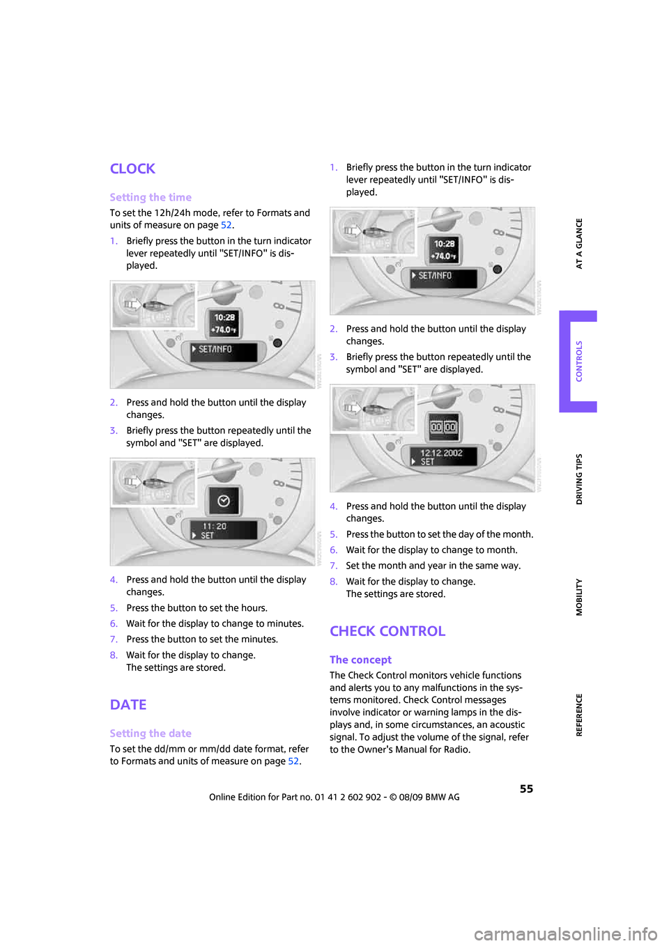
Setting the time
To set the 12h/24h mode, refer to Formats and
units of measure on page52.
1.Briefly press the button in the turn indicator
lever repeatedly until "SET/INFO" is dis-
played.
2.Press and hold the button until the display
changes.
3.Briefly press the button repeatedly until the
symbol and "SET" are displayed.
4.Press and hold the button until the display
changes.
5.Press the button to set the hours.
6.Wait for the display to change to minutes.
7.Press the button to set the minutes.
8.Wait for the display to change.
The settings are stored.
Date
Setting the date
To set the dd/mm or mm/dd date format, refer
to Formats and units of measure on page52.1.Briefly press the button in the turn indicator
lever repeatedly until "SET/INFO" is dis-
played.
2.Press and hold the button until the display
changes.
3.Briefly press the button repeatedly until the
symbol and "SET" are displayed.
4.Press and hold the button until the display
changes.
5.Press the button to set the day of the month.
6.Wait for the display to change to month.
7.Set the month and year in the same way.
8.Wait for the display to change.
The settings are stored.
Check Control
The concept
The Check Control monitors vehicle functions
and alerts you to any malfunctions in the sys-
tems monitored. Check Control messages
involve indicator or warning lamps in the dis-
plays and, in some circumstances, an acoustic
signal. To adjust the volume of the signal, refer
to the Owner's Manual for Radio.
Page 60 of 160
Technology for driving comfort and safety
58
in hazardous driving thereby running the risk of
an accident.<
Antilock Brake System ABS
ABS prevents locking of the wheels during brak-
ing. Safe steering response is maintained even
during full braking. Active safety is thus
increased.
Braking safely, refer to page85.
Among others, ABS includes the following func-
tions:
>Cornering Brake Control CBC
>Electronic brake-force distribution EBV
>Brake Assist
Cornering Brake Control CBC
Driving stability and steering characteristics are
further enhanced while braking in turns or dur-
ing a lane change.
Electronic brake-force distribution EBV
The system controls the brake pressure in the
rear wheels to ensure stable braking behavior.
Brake Assist
Rapidly depressing the brake causes this system
to automatically develop maximum braking
force. Thus, the system helps keep braking dis-
tance to a minimum. At the same time, all the
benefits provided by ABS are exploited.
Do not reduce the pressure on the brake for the
duration of the full braking application.
Dynamic Stability Control DSC
DSC prevents the driving wheels from losing
traction when you pull away from rest or accel-
erate. The system also recognizes unstable driv-
ing conditions, for example if the rear of the car
is about to swerve or if momentum is acting at
an angle past the front wheels. In these cases,
DSC helps the vehicle maintain a safe course
within physical limits by reducing engine output
and through braking actions at the individual
wheels.DSC also encompasses the following functions:
>Antilock Brake System ABS
>Electronic brake-force distribution EBV
>Brake Assist
>Cornering Brake Control CBC
>Hill Assist
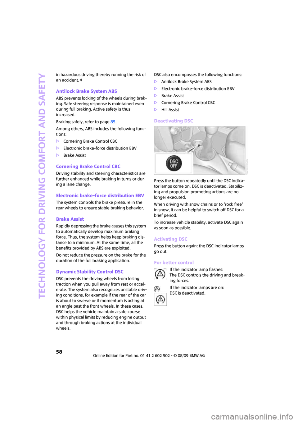
Deactivating DSC
Press the button repeatedly until the DSC indica-
tor lamps come on. DSC is deactivated. Stabiliz-
ing and propulsion promoting actions are no
longer executed.
When driving with snow chains or to 'rock free'
in snow, it can be helpful to switch off DSC for a
brief period.
To increase vehicle stability, activate DSC again
as soon as possible.
Activating DSC
Press the button again: the DSC indicator lamps
go out.
For better control
If the indicator lamp flashes:
The DSC controls the driving and break-
ing forces.
If the indicator lamps are on:
DSC is deactivated.
Page 61 of 160
REFERENCEAT A GLANCE CONTROLS DRIVING TIPS MOBILITY
59
Dynamic Traction Control DTC*
DTC is a type of DSC that is propulsion optimized
for special road conditions such as uncleared
snowy roads. The system ensures maximum
propulsion though with restricted driving stabil-
ity. You therefore need to drive with suitable
caution.
In the following exceptional situations, it can be
useful to briefly activate DTC:
>when driving on snow-covered inclines, in
slush, or on uncleared snowy roads
>when rocking the vehicle free, driving out of
deep snow or on loose surfaces
>when driving with snow chains
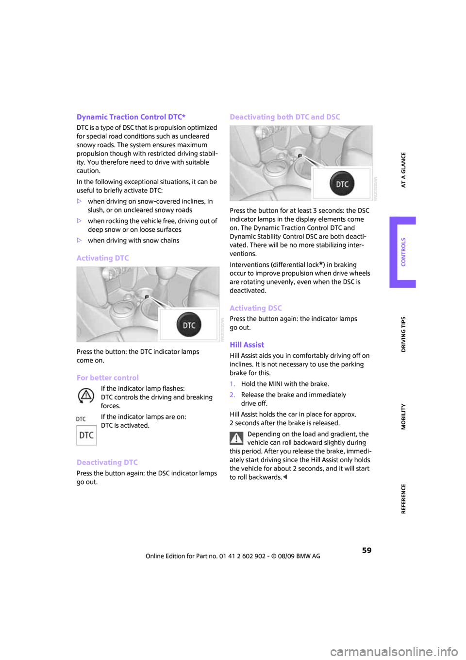
Activating DTC
Press the button: the DTC indicator lamps
come on.
For better control
If the indicator lamp flashes:
DTC controls the driving and breaking
forces.
If the indicator lamps are on:
DTC is activated.
Deactivating DTC
Press the button again: the DSC indicator lamps
go out.
Deactivating both DTC and DSC
Press the button for at least 3 seconds: the DSC
indicator lamps in the display elements come
on. The Dynamic Traction Control DTC and
Dynamic Stability Control DSC are both deacti-
vated. There will be no more stabilizing inter-
ventions.
Interventions (differential lock
*) in braking
occur to improve propulsion when drive wheels
are rotating unevenly, even when the DSC is
deactivated.
Activating DSC
Press the button again: the indicator lamps
go out.
Hill Assist
Hill Assist aids you in comfortably driving off on
inclines. It is not necessary to use the parking
brake for this.
1.Hold the MINI with the brake.
2.Release the brake and immediately
drive off.
Hill Assist holds the car in place for approx.
2 seconds after the brake is released.
Depending on the load and gradient, the
vehicle can roll backward slightly during
this period. After you release the brake, immedi-
ately start driving since the Hill Assist only holds
the vehicle for about 2 seconds, and it will start
to roll backwards.<
Page 69 of 160
REFERENCEAT A GLANCE CONTROLS DRIVING TIPS MOBILITY
67
Lamps
Parking lamps/low beams
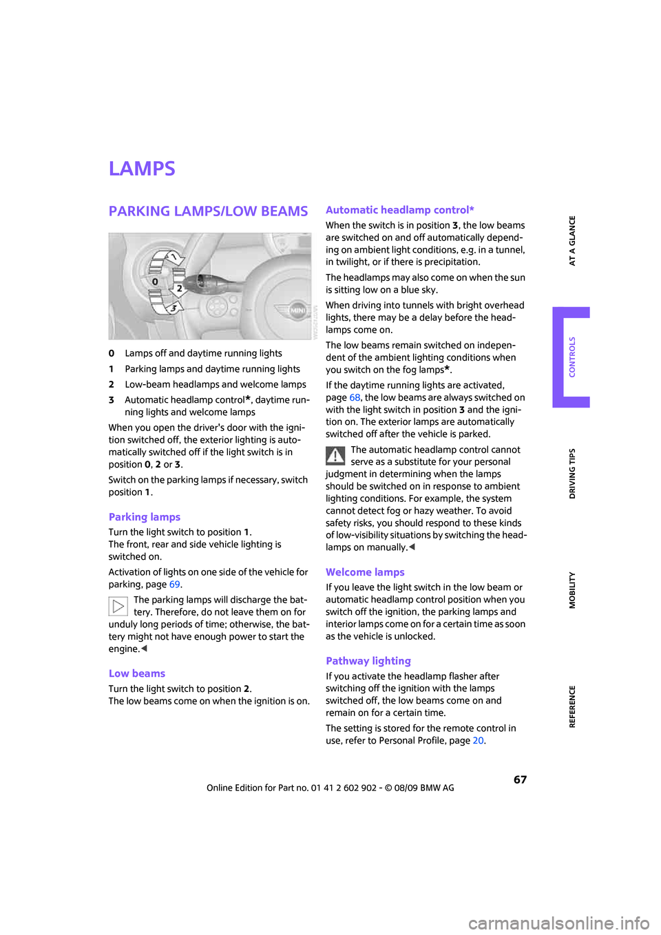
0Lamps off and daytime running lights
1Parking lamps and daytime running lights
2Low-beam headlamps and welcome lamps
3Automatic headlamp control
*, daytime run-
ning lights and welcome lamps
When you open the driver's door with the igni-
tion switched off, the exterior lighting is auto-
matically switched off if the light switch is in
position 0, 2 or 3.
Switch on the parking lamps if necessary, switch
position 1.
Parking lamps
Turn the light switch to position 1.
The front, rear and side vehicle lighting is
switched on.
Activation of lights on one side of the vehicle for
parking, page69.
The parking lamps will discharge the bat-
tery. Therefore, do not leave them on for
unduly long periods of time; otherwise, the bat-
tery might not have enough power to start the
engine.<
Low beams
Turn the light switch to position 2.
The low beams come on when the ignition is on.
Automatic headlamp control*
When the switch is in position3, the low beams
are switched on and off automatically depend-
ing on ambient light conditions, e.g. in a tunnel,
in twilight, or if there is precipitation.
The headlamps may also come on when the sun
is sitting low on a blue sky.
When driving into tunnels with bright overhead
lights, there may be a delay before the head-
lamps come on.
The low beams remain switched on indepen-
dent of the ambient lighting conditions when
you switch on the fog lamps
*.
If the daytime running lights are activated,
page68, the low beams are always switched on
with the light switch in position 3 and the igni-
tion on. The exterior lamps are automatically
switched off after the vehicle is parked.
The automatic headlamp control cannot
serve as a substitute for your personal
judgment in determining when the lamps
should be switched on in response to ambient
lighting conditions. For example, the system
cannot detect fog or hazy weather. To avoid
safety risks, you should respond to these kinds
of low-visibility situations by switching the head-
lamps on manually.<
Welcome lamps
If you leave the light switch in the low beam or
automatic headlamp control position when you
switch off the ignition, the parking lamps and
interior lamps come on for a certain time as soon
as the vehicle is unlocked.
Pathway lighting
If you activate the headlamp flasher after
switching off the ignition with the lamps
switched off, the low beams come on and
remain on for a certain time.
The setting is stored for the remote control in
use, refer to Personal Profile, page20.
Page 88 of 160
Things to remember when driving
86
Cargo loading
To avoid loading the tires beyond their
approved carrying capacity, never over-
load the vehicle. Overloading can lead to over-
heating and increases the rate at which damage
develops inside the tires. The ultimate result can
assume the form of a sudden blowout.<
Avoid fluid spills in the cargo bay as they
could damage the vehicle.<
Cargo bay cover
Do not place any objects on the cover;
otherwise, they could endanger the car's
occupants, e.g. in the case of braking or sudden
swerving, or they may damage the cover.<
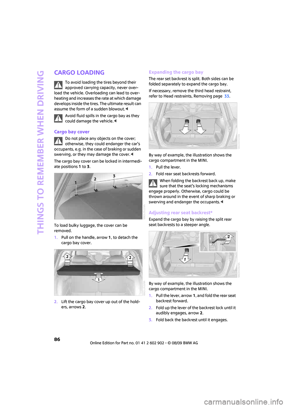
The cargo bay cover can be locked in intermedi-
ate positions 1to3.
To load bulky luggage, the cover can be
removed.
1.Pull on the handle, arrow1, to detach the
cargo bay cover.
2.Lift the cargo bay cover up out of the hold-
ers, arrows 2.
Expanding the cargo bay
The rear set backrest is split. Both sides can be
folded separately to expand the cargo bay.
If necessary, remove the third head restraint,
refer to Head restraints, Removing page 33.
By way of example, the illustration shows the
cargo compartment in the MINI.
1.Pull the lever.
2.Fold rear seat backrests forward.
When folding the backrest back up, make
sure that the seat's locking mechanisms
engage properly. Otherwise, cargo could be
thrown around in the event of sharp braking or
swerving and endanger the occupants.<
Adjusting rear seat backrest*
Expand the cargo bay by raising the split rear
seat backrests to a steeper angle.
By way of example, the illustration shows the
cargo compartment in the MINI.
1.Pull the lever, arrow1, and fold the rear seat
backrest forward.
2.Fold up the lever of the backrest lock until it
audibly engages, arrow2.
3.Fold back the backrest until it engages.