warning MINI Clubman 2011 (Mini Connected) User Guide
[x] Cancel search | Manufacturer: MINI, Model Year: 2011, Model line: Clubman, Model: MINI Clubman 2011Pages: 256, PDF Size: 3.75 MB
Page 66 of 256
CONTROLSControls overview
64
Check Control
The concept
The Check Control monitors vehicle functions
and alerts you to any malfunctions in the sys-
tems monitored. Check Control messages
involve indicator and warning lamps in the dis-
play and, in some circumstances, an acoustic
signal as well as text messages at the bottom of
the Control Display.
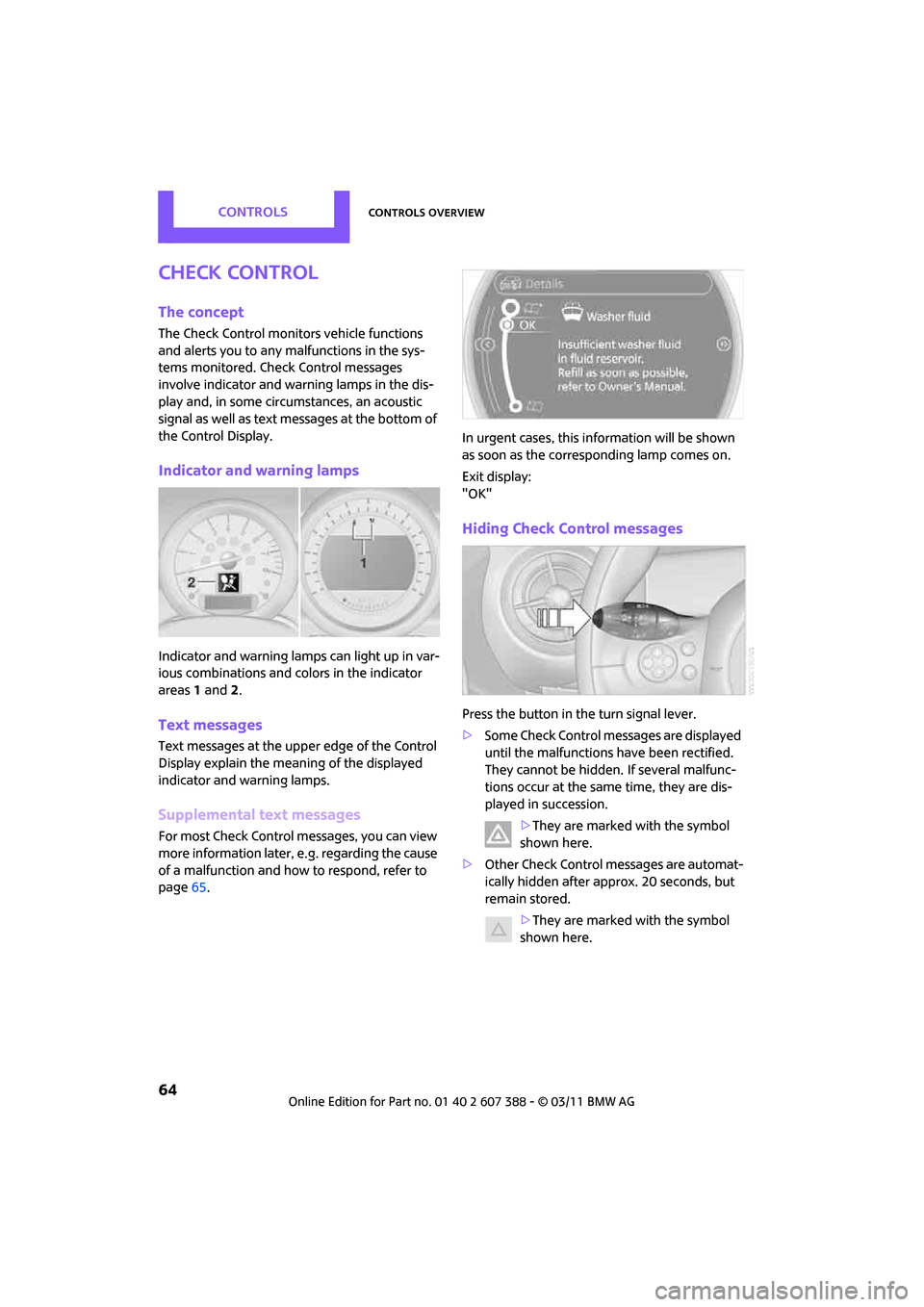
Indicator and warning lamps
Indicator and warning lamps can light up in var-
ious combinations and colors in the indicator
areas 1 and 2.
Text messages
Text messages at the uppe r edge of the Control
Display explain the mean ing of the displayed
indicator and warning lamps.
Supplemental text messages
For most Check Control messages, you can view
more information later, e.g. regarding the cause
of a malfunction and how to respond, refer to
page 65. In urgent cases, this information will be shown
as soon as the corresponding lamp comes on.
Exit display:
"OK"
Hiding Check Control messages
Press the button in th
e turn signal lever.
> Some Check Control messages are displayed
until the malfunctions have been rectified.
They cannot be hidden. If several malfunc-
tions occur at the same time, they are dis-
played in succession.
>They are marked with the symbol
shown here.
> Other Check Control messages are automat-
ically hidden after approx. 20 seconds, but
remain stored.
>They are marked with the symbol
shown here.
Page 67 of 256
Controls overviewCONTROLS
65
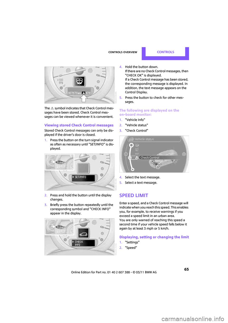
The symbol indicates that Check Control mes-
sages have been stored. Check Control mes-
sages can be viewed when ever it is convenient.
Viewing stored Check Control messages
Stored Check Control messages can only be dis-
played if the driver's door is closed.
1.Press the button on the turn signal indicator
as often as necessary until "SET/INFO" is dis-
played.
2. Press and hold the butt on until the display
changes.
3. Briefly press the button repeatedly until the
corresponding symbol and "CHECK INFO"
appear in the display. 4.
Hold the button down.
If there are no Check Control messages, then
"CHECK OK" is displayed.
If a Check Control messa ge has been stored,
the corresponding message is displayed. In
addition, the text message appears on the
Control Display.
5. Press the button to check for other mes-
sages.
The following are displayed on the
on-board monitor:
1."Vehicle Info"
2. "Vehicle status"
3. "Check Control"
4. Select the text message.
5. Select a text message.
Speed limit
Enter a speed, and a Check Control message will
indicate when you reach this speed. This enables
you, for example, to receive warnings if you
exceed a speed limit in an urban area.
You are only warned of reaching this speed a
second time if your vehicle speed falls below it
again by at least 3 mph or 5 km/h.
Displaying, setting or changing the limit
1. "Settings"
2. "Speed"
Page 68 of 256
CONTROLSControls overview
66
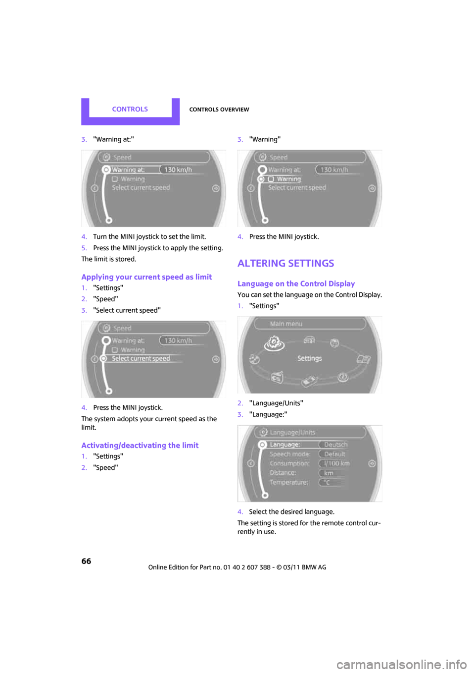
3."Warning at:"
4. Turn the MINI joystick to set the limit.
5. Press the MINI joystick to apply the setting.
The limit is stored.
Applying your current speed as limit
1. "Settings"
2. "Speed"
3. "Select current speed"
4. Press the MINI joystick.
The system adopts your current speed as the
limit.
Activating/deactivating the limit
1. "Settings"
2. "Speed" 3.
"Warning"
4. Press the MINI joystick.
Altering settings
Language on the Control Display
You can set the language on the Control Display.
1."Settings"
2. "Language/Units"
3. "Language:"
4. Select the desired language.
The setting is stored fo r the remote control cur-
rently in use.
Page 70 of 256
CONTROLSTechnology for driving comfort and safety
68
Technology for driving comfort and
safety
Park Distance Control
PDC*
The concept
PDC assists you with parking in reverse. Acoustic
signals and a visual indicator
warn you of the
presence of an object behind the vehicle. To
measure the distance, there are four ultrasonic
sensors in either bumper.
These sensors have a range of approx.
6.5 ft/2 m. However, an acoustic warning
does not sound until an object is approx. 24 in/
60 cm from the rear corner sensors, or approx.
5 ft/1.50 m from the rear center sensors. PDC is
a parking aid that can indicate objects when
they are approached slowly, as is usually the
case when parking. Avoid approaching an
object at high speed; ot herwise, physical cir-
cumstances may lead to the system warning
being issued too late. <
Automatic mode
With the engine running or the ignition switched
on, the system is activated automatically after
approx. 1 second when you engage reverse
gear or move the automatic transmission selec-
tor lever to position R. Wait this short period
before driving.
Acoustic signals
As the distance between vehicle and object
decreases, the intervals between the tones
become shorter. If the distance to the nearest
object falls to below roughly 1 ft/30 cm, then a
continuous tone sounds.
If the distance remains co nstant, e.g. when driv-
ing parallel to a wall, th e acoustic signal stops
after approx. 3 seconds.
Malfunction
Indicator lamp lights up: PDC has failed.
A message appears on the Control Dis-
play. Have the system checked.
To avoid this problem, keep the sensors clean
and free of ice or snow in order to ensure that
they will continue to operate effectively. When
using a high-pressure cleaner, do not direct the
jet toward the sensors for lengthy periods and
only spray from a distance of at least 4 in/10 cm.
PDC with visual warning
To have the system show distances to objects on
the Control Display. The contours of distant
objects are shown on the Control Display even
before the acoustic sign al sounds. The display
appears on the Control Display as soon as the
transmission is shifted into reverse or the selec-
tor lever is moved into the R position.
System limitations
Even with PDC, final responsibility for esti-
mating the distance between the vehicle
and any obstructions always remains with the
driver. Sensors, too, have blind spots in which
objects cannot be dete cted. Moreover, ultra-
sonic detection can reach its physical limits with
objects such as trailer tow bars and couplings,
thin and wedge-shaped objects, etc. Low
objects already indicated, such as curbs, may
enter the sensors' blind spots before or after a
continuous audible signal is given. Higher, pro-
truding objects, such as wall ledges, may not be
detectable. Therefore, always drive cautiously;
otherwise, there is a risk of personal injury or
property damage. Loud sound sources outside
or inside the car can drown out the PDC signal. <
Page 75 of 256
Technology for driving comfort and safetyCONTROLS
73
Indication of a flat tire
The warning lamps come on in yellow
and red. A message appears on the
Control Display. An acoustic signal also
sounds. There is a flat tire or a major loss
in tire inflation pressure.
1. Reduce speed and stop the vehicle with cau-
tion. Avoid sudden braking and steering
maneuvers.
2. Check whether the vehicle is equipped with
normal tires or with run-flat tires
*.
Run-flat tires, refer to page 196, are identi-
fied by a circular symbol containing the let-
ters RSC on the tire sidewall.
If the vehicle is not equipped with run-flat
tires, do not continue driving; continuing
to drive can result in serious accidents. <
When a flat tire is repo rted, the Dynamic Stability
Control DSC is activated.
Actions in the event of a flat tire
Normal tires
1. Identify the damaged tire.
To do so, check the inflation pressure in all
four tires.
The inflation pressure di splay of the Mobility
System, page 213, can be used for this pur-
pose.
If the inflation pressure in all four tires is cor-
rect, the Flat Tire Monitor might not have
been initialized. The system must then be
initialized.
If it is not possible to identify the damaged
tire, contact your MINI dealer.
2. Use the Mobility System to remedy the flat
tire on the damage d wheel, refer to
page 213, or to replace the damaged wheel,
refer to page 215.
Run-flat tires*
You can continue driving with a damaged tire at
speeds up to 50 mph or 80 km/h.
Continued driving with a flat tire
When driving with a damaged tire:
1.Avoid sudden braking and steering maneu-
vers.
2. Do not exceed a speed of 50 mph or
80 km/h.
3. At the next opportunity, check the air pres-
sure in all four tires.
If the inflation pressure in all four tires is cor-
rect, the Flat Tire Monitor might not have
been initialized. The system must then be
initialized.
Possible driving distance with complete loss of
tire inflation pressure:
The distance it is possible to drive with a flat tire
depends on the load and the stress on the vehi-
cle while driving.
With an average load, it may be possible to drive
for approx. 50 miles/80 km.
When driving with damage d tires, the handling
characteristics change, e.g. the vehicle will skid
sooner when braking, braking distances will be
longer, or self-steering response will change.
Adapt your driving style accordingly. Avoid turn-
ing abruptly and driving over obstacles such as
curbs, potholes, etc.
Since the possible driving distance depends to a
considerable degree on the strain exerted on
the vehicle while driving, it can be shorter or,
with a gentle dr iving style, can also be longer,
depending on the speed, road condition, exter-
nal temperature, vehicle load, etc.
Drive cautiously and do not exceed a
speed of 50 mph/80 km/h.
A loss of tire inflation pressure results in a
change in the handling characteristics, e.g.
reduced lane stability during braking, a longer
braking distance and alte red self-steering prop-
erties. <
Page 77 of 256
Technology for driving comfort and safetyCONTROLS
75
All wheels yellow
>There is a flat tire or substantial loss of tire
pressure in several tires.
> The system was not reset after a wheel
change and thus issues a warning based on
the inflation pressures initialized last.
Gray wheels
The system cannot detect a puncture.
Reasons for this may be:
>TPM is being reset.
> Interference from systems or devices with
the same transmission frequency.
> Malfunction.
Resetting the system
Reset the system again after each correction of
the tire inflation pressure and after every tire or
wheel change.
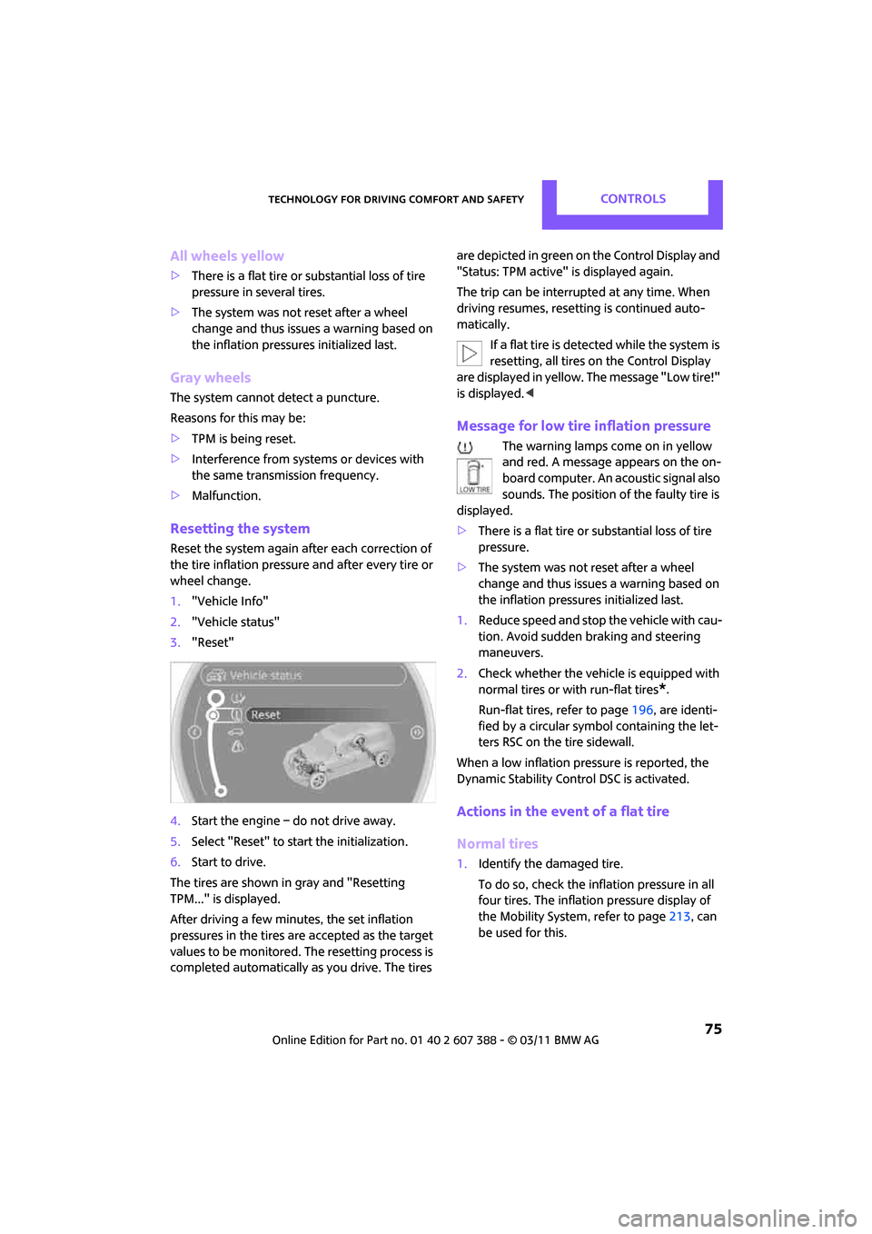
1. "Vehicle Info"
2. "Vehicle status"
3. "Reset"
4. Start the engine – do not drive away.
5. Select "Reset" to start the initialization.
6. Start to drive.
The tires are shown in gray and "Resetting
TPM..." is displayed.
After driving a few minutes, the set inflation
pressures in the tires are accepted as the target
values to be monitored. The resetting process is
completed automatically as you drive. The tires are depicted in green on the Control Display and
"Status: TPM active" is displayed again.
The trip can be interrupt
ed at any time. When
driving resumes, resetti ng is continued auto-
matically.
If a flat tire is detected while the system is
resetting, all tires on the Control Display
are displayed in yellow. The message "Low tire!"
is displayed. <
Message for low tire inflation pressure
The warning lamps come on in yellow
and red. A message appears on the on-
board computer. An ac oustic signal also
sounds. The position of the faulty tire is
displayed.
> There is a flat tire or substantial loss of tire
pressure.
> The system was not reset after a wheel
change and thus issues a warning based on
the inflation pressures initialized last.
1. Reduce speed and stop the vehicle with cau-
tion. Avoid sudden braking and steering
maneuvers.
2. Check whether the vehicle is equipped with
normal tires or with run-flat tires
*.
Run-flat tires, refer to page 196, are identi-
fied by a circular symbol containing the let-
ters RSC on the tire sidewall.
When a low inflation pressure is reported, the
Dynamic Stability Control DSC is activated.
Actions in the event of a flat tire
Normal tires
1. Identify the damaged tire.
To do so, check the inflation pressure in all
four tires. The inflation pressure display of
the Mobility System, refer to page 213, can
be used for this.
Page 78 of 256
CONTROLSTechnology for driving comfort and safety
76
If the inflation pressure is correct in all four
tires, then the Tire Pressure Monitor may not
have been reset. The system must then be
reset.
If it is not possible to identify the damaged
tire, contact your MINI dealer.
2. Use the Mobility System to remedy the flat
tire on the damaged wheel, refer to
page 213, or to replace the damaged wheel,
refer to page. 215.
The use of tire sealant, e.g. Mobility System,
can damage the TPM wheel electronics. In
this case, have the el ectronics checked and
replaced if necessary at your earliest oppor-
tunity.
Run-flat tires*
You can continue driving with a damaged tire at
speeds up to 50 mph/80 km/h.
If the vehicle is not equipped with run-flat
tires, do not continue driving; continuing
to drive can result in serious accidents. <
Continued driving with a flat tire
When driving with a damaged tire:
1.Avoid sudden braking and steering maneu-
vers.
2. Do not exceed a speed of 50 mph/80 km/h.
3. At the next opportunity, check the air pres-
sure in all four tires.
If the inflation pressure is correct in all four
tires, then the Tire Pressure Monitor may not
have been reset. The system must then be
reset.
Possible driving distance with complete loss of
tire inflation pressure:
The distance it is possible to drive with a flat tire
depends on the load and the stress on the vehi-
cle while driving.
With an average load, it may be possible to drive
for approx. 50 miles/80 km.
When driving with damaged tires, the handling
characteristics change, e.g. the vehicle will skid sooner when braking, braking distances will be
longer, or self-steerin
g response will change.
Adapt your driving style accordingly. Avoid turn-
ing abruptly and driving over obstacles such as
curbs, potholes, etc.
Since the possible driving distance depends to a
considerable degree on the strain exerted on
the vehicle while driving, it can be shorter or,
with a gentle driving styl e, can also be longer,
depending on the speed, road condition, exter-
nal temperature, vehicle load, etc.
Drive cautiously and do not exceed a
speed of 50 mph/80 km/h.
A loss of tire inflation pressure results in a
change in the handling characteristics, e.g.
reduced lane stability during braking, a longer
braking distance and alte red self-steering prop-
erties. <
Vibrations or loud no ises while driving can
indicate complete failure of the tire.
Reduce your speed and bring the vehicle to a
stop; otherwise, pieces of tire may come off,
which could result in an accident. Do not con-
tinue driving and contac t your MINI dealer.
low and then lights up continuously; the
larger warning lamp lights up in yellow.
On the on-board computer, the tires are
shown in gray and a message appears.
No flat tire can be detected.
Display in the following situations:
> Wheel without TPM electronics is mounted:
If need be, have it checked by your MINI
dealer.
> Malfunction:
Have the system checked.
> TPM was unable to complete the resetting
procedure; reset the system again.
The small warning lamp flashes in yel-
low and then lights up continuously; the
larger warning lamp lights up in yellow.
Page 79 of 256
Technology for driving comfort and safetyCONTROLS
77
On the on-board computer, the tires are shown
in gray and a message appears.
No punctures can be detected.
Display in the following situation:
>Malfunction because of other equipment or
devices, same radio frequency:
After leaving the interf erence area, the sys-
tem is again active automatically.
Message for unsuccessful system reset
Yellow warning light is on. A message
appears on the on-board computer.
The system has detected a wheel change, but
has not yet been reset. It is not possible to pro-
vide a reliable warning about the current infla-
tion pressure.
Check the tire inflation pressure and reset the
system, page 75.
Declaration according to NHTSA/
FMVSS 138 Tire Pressure Monitoring
Systems
Each tire, including the spare, should be
checked monthly when cold and inflated to the
inflation pressure recommended by the vehicle
manufacturer on the vehicle placard or tire infla-
tion pressure label. If yo ur vehicle has tires of a
different size than the size indicated on the vehi-
cle placard or tire inflat ion pressure label, you
should determine the prop er tire inflation pres-
sure for those tires. As an added safety feature,
your vehicle has been equipped with a tire pres-
sure monitoring system TPMS that illuminates a
low tire pressure telltale when one or more of
your tires are significantly underinflated.
Accordingly, when the low tire pressure telltale
illuminates, you should st op and check your tires
as soon as possible, an d inflate them to the
proper pressure. Drivin g on a significantly
underinflated tire causes the tire to overheat
and can lead to tire failure. Underinflation also
reduces fuel efficiency and tire tread life, and
may affect the vehicle's handling and stopping ability. Please note that the TPMS is not a substi-
tute for proper tire maintenance, and it is the
driver's responsibility to
maintain correct tire
pressure, even if underi nflation has not reached
the level at which the TPMS low tire pressure tell-
tale illuminates.
The TPMS malfunction indicator is combined
with the low tire pressure telltale. When the sys-
tem detects a malfunction, the telltale will flash
for approximately one minute and then remain
continuously lit. This sequence will continue
upon subsequent vehicle startups as long as the
malfunction exists. When the malfunction indi-
cator is illuminated, the system may not be able
to detect or signal low tire pressure as intended.
TPMS malfunctions may occur for a variety of
reasons, including the in stallation of replace-
ment or alternate tires or wheels on the vehicle
that prevent the TPMS from functioning prop-
erly. Always check the TP MS malfunction telltale
after replacing one or mo re tires or wheels on
your vehicle to ensure that the replacement or
alternate tires and wheels allow the TPMS to
continue to function properly.
Page 80 of 256
CONTROLSTechnology for driving comfort and safety
78
Airbags
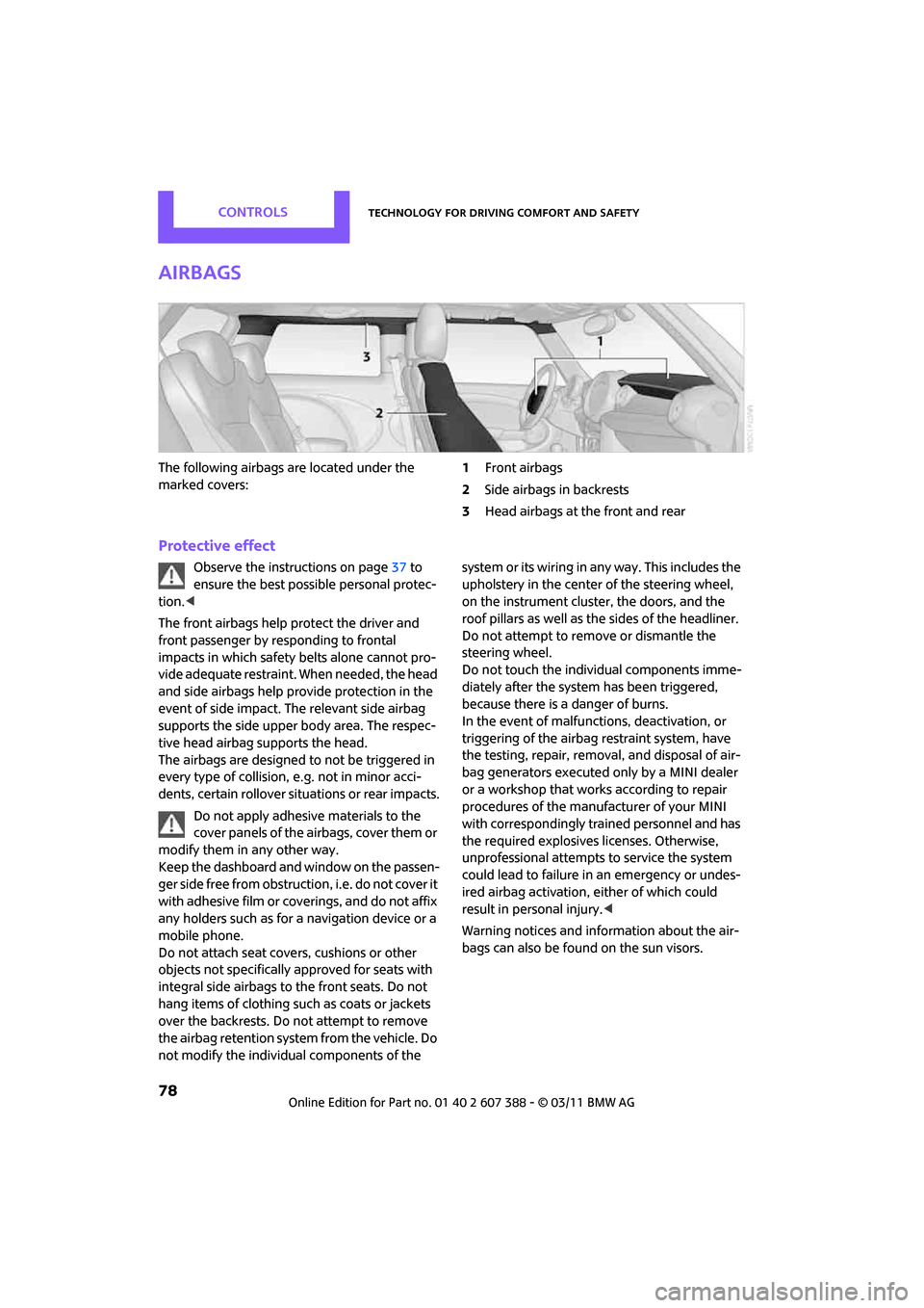
The following airbags are located under the
marked covers:1
Front airbags
2 Side airbags in backrests
3 Head airbags at the front and rear
Protective effect
Observe the instructions on page 37 to
ensure the best possible personal protec-
tion. <
The front airbags help protect the driver and
front passenger by re sponding to frontal
impacts in which safety belts alone cannot pro-
vide adequate restraint. When needed, the head
and side airbags help provide protection in the
event of side impact. The relevant side airbag
supports the side upper body area. The respec-
tive head airbag supports the head.
The airbags are designed to not be triggered in
every type of collision, e.g. not in minor acci-
dents, certain rollover situations or rear impacts.
Do not apply adhesive materials to the
cover panels of the airbags, cover them or
modify them in any other way.
Keep the dashboard and window on the passen-
g e r s i d e f r e e f r o m o b s t r u c t i o n , i . e . d o n o t c o v e r i t
with adhesive film or co verings, and do not affix
any holders such as for a navigation device or a
mobile phone.
Do not attach seat cove rs, cushions or other
objects not specifically approved for seats with
integral side airbags to the front seats. Do not
hang items of clothing su ch as coats or jackets
over the backrests. Do not attempt to remove
the airbag retention system from the vehicle. Do
not modify the individual components of the syste m o r its w iring in any way. Th is includ es the
upholstery in the center of the steering wheel,
on the instrument cluster, the doors, and the
roof pillars as well as the sides of the headliner.
Do not attempt to remove or dismantle the
steering wheel.
Do not touch the individual components imme-
diately after the system has been triggered,
because there is a danger of burns.
In the event of malfunctions, deactivation, or
triggering of the airbag
restraint system, have
the testing, repair, remova l, and disposal of air-
bag generators executed only by a MINI dealer
or a workshop that work s according to repair
procedures of the manufacturer of your MINI
with correspondingly trained personnel and has
the required explosives licenses. Otherwise,
unprofessional attempts to service the system
could lead to failure in an emergency or undes-
ired airbag activation, either of which could
result in personal injury. <
Warning notices and information about the air-
bags can also be found on the sun visors.
Page 82 of 256

CONTROLSTechnology for driving comfort and safety
80
Operational readiness of airbag system
As of radio readiness, page46, the warning
lamp lights up briefly to indicate that the entire
airbag system and the be lt tensioners are oper-
ational.
Airbag system malfunction
> The warning lamp does not come on when
radio readiness is switched on.
> The warning lamp stays lit continuously.
In the event of a fault in the airbag system,
have it checked without delay; otherwise,
there is the risk that the system will not function
as intended even if a severe accident occurs. <