warning MINI Clubman 2011 Owner's Manual (Mini Connected)
[x] Cancel search | Manufacturer: MINI, Model Year: 2011, Model line: Clubman, Model: MINI Clubman 2011Pages: 256, PDF Size: 3.75 MB
Page 7 of 256
NotesNotes
5
Status of this Owner's
Manual at time of
printing
The high level of safety and quality of the MINI
vehicles is ensured through continuous develop-
ment. In rare cases, there may be differences
between the description and the vehicle.
For your safety
Maintenance and repair
Advanced technology, e.g. the use of
modern materials an d high-performance
electronics, requires specially adapted mainte-
nance and repair methods. Therefore, have the
necessary work on your MI NI only carried out by
a MINI dealer or a work shop that has specially
trained personnel workin g in accordance with
the specifications of the MINI manufacturer. If
this work is not carried out properly, there is a
danger of subsequent damage and related
safety hazards. <
Parts and accessories
For your own safety, use genuine parts
and accessories approved by the manu-
facturer of the MINI.
When you purchase accessories tested
and approved by the manufacturer of the MINI
and Original MINI Parts, you simultaneously
acquire the assurance that they have been thor-
oughly tested by the manufacturer of the MINI
to ensure optimum performance when installed
on your vehicle.
The manufacturer of the MINI warrants these
parts to be free from defects in material and
workmanship.
The manufacturer of the MINI will not accept any
liability for damage result ing from installation of
parts and accessories not approved by the man-
ufacturer of the MINI. The manufacturer of the MINI cannot test every
product made by other manufacturers to verify
if it can be used on a MINI safely and without risk
to either the vehicle, its operation, or its occu-
pants.
Original MINI Parts, MINI Accessories and other
products approved by the manufacturer of the
MINI, together with professional advice on using
these items, are available from all MINI dealers.
Installation and operation of accessories that
have not been approved by the manufacturer of
your MINI, such as alarms, radios, amplifiers,
radar detectors, wheels, suspension compo-
nents, brake dust shield
s, telephones, including
operation of any mobile phone from within the
vehicle without using an externally mounted
antenna, or transceiver equipment, for instance,
CBs, walkie-talkies, ham radios or similar acces-
sories, may cause extensiv e damage to the vehi-
cle, compromise its safety, interfere with the
vehicle's electrical s y s t e m o r a f f e c t t h e v a l i d i t y o f
the MINI Limited Warranty. See your MINI dealer
for additional information. <
Maintenance, replacement, or repair of
the emission control devices and systems
may be performed by any automotive repair
establishment or individu al using any certified
automotive part. <
California Proposition 65 warning
California law requires us to issue the following
warning:
Engine exhaust and a wide variety of
automobile components and parts,
including components foun d in the interior fur-
nishings in a vehicle, contain or emit chemicals
known to the State of California to cause cancer
and birth defects and reproductive harm. In
addition, certain fluids co ntained in vehicles and
certain products of component wear contain or
emit chemicals known to the State of California
to cause cancer and birth defects or other repro-
ductive harm.
Page 14 of 256
AT A GLANCECockpit
12
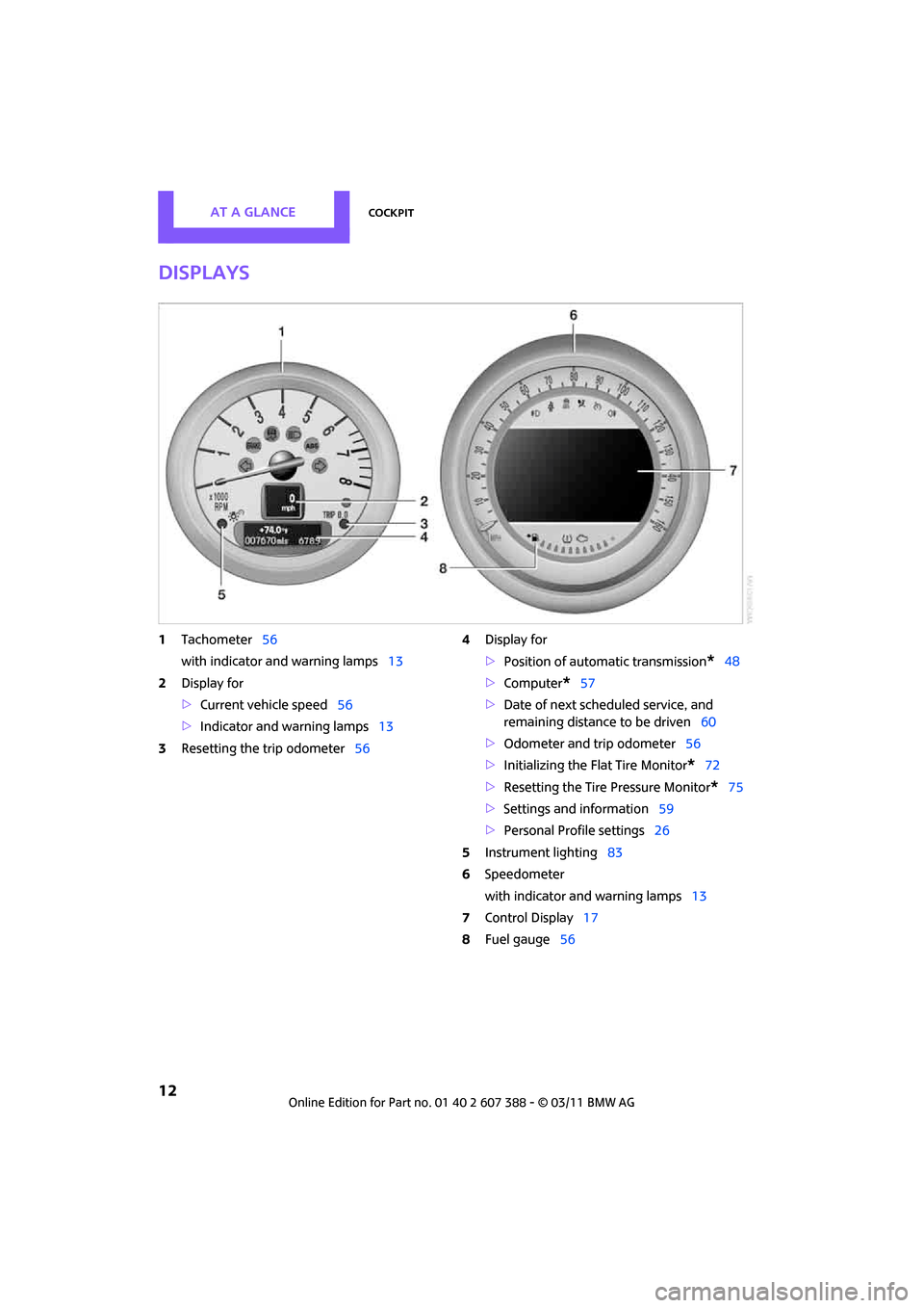
Displays
1Tachometer 56
with indicator and warning lamps 13
2 Display for
>Current vehicle speed 56
> Indicator and warning lamps 13
3 Resetting the trip odometer 564
Display for
>Position of automatic transmission
*48
> Computer
*57
> Date of next scheduled service, and
remaining distance to be driven 60
> Odometer and trip odometer 56
> Initializing the Flat Tire Monitor
*72
> Resetting the Tire Pressure Monitor
*75
> Settings and information 59
> Personal Prof ile settings26
5 Instrument lighting 83
6 Speedometer
with indicator and warning lamps 13
7 Control Display 17
8 Fuel gauge 56
Page 15 of 256
CockpitAT A GLANCE
13
Indicator and warning
lamps
The concept
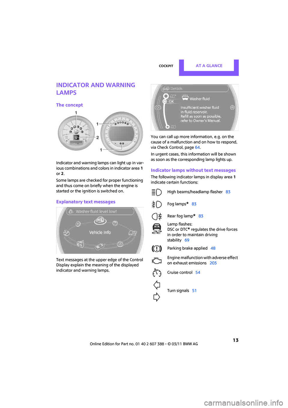
Indicator and warning lamps can light up in var-
ious combinations and colors in indicator area1
or 2.
Some lamps are checked for proper functioning
and thus come on briefly when the engine is
started or the ignition is switched on.
Explanatory text messages
Text messages at the uppe r edge of the Control
Display explain the mean ing of the displayed
indicator and warning lamps. You can call up more information, e.g. on the
cause of a malfunction and on how to respond,
via Check Control, page
64.
In urgent cases, this information will be shown
as soon as the corresponding lamp lights up.
Indicator lamps without text messages
The following indicator lamps in display area 1
indicate certain functions:
High beams/headlamp flasher 83
Fog lamps
*83
Rear fog lamp
*83
Lamp flashes:
DSC or DTC
* regulates the drive forces
in order to maintain driving
stability 69
Parking brake applied 48
Engine malfunction with adverse effect
on exhaust emissions 203
Cruise control 54
Turn signals 51
Page 17 of 256
CockpitAT A GLANCE
15
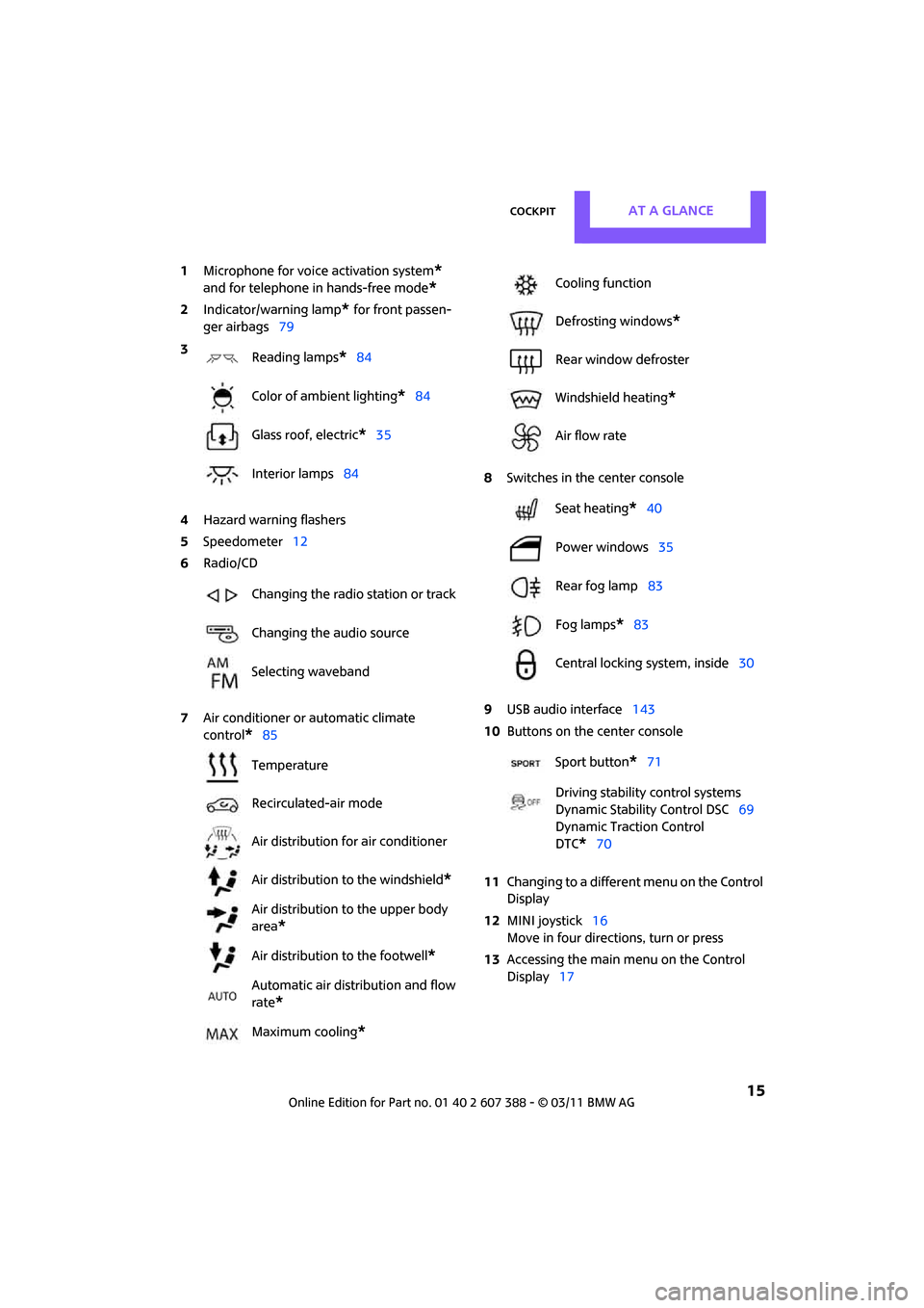
1Microphone for voice activation system*
and for telephone in hands-free mode*
2Indicator/warning lamp* for front passen-
ger airbags 79
4 Hazard warning flashers
5 Speedometer 12
6 Radio/CD
7 Air conditioner or automatic climate
control
*85 8
Switches in the center console
9 USB audio interface 143
10 Buttons on the center console
11 Changing to a differen t menu on the Control
Display
12 MINI joystick 16
Move in four directions, turn or press
13 Accessing the main me nu on the Control
Display 17
3
Reading lamps
*84
Color of ambient lighting
*84
Glass roof, electric
*35
Interior lamps 84
Changing the radio station or track
Changing the audio source
Selecting waveband
Temperature
Recirculated-air mode
Air distribution for air conditioner
Air distribution to the windshield
*
Air distribution to the upper body
area
*
Air distribution to the footwell*
Automatic air distribution and flow
rate
*
Maximum cooling*
Cooling function
Defrosting windows
*
Rear window defroster
Windshield heating
*
Air flow rate
Seat heating
*40
Power windows 35
Rear fog lamp 83
Fog lamps
*83
Central locking system, inside 30
Sport button
*71
Driving stability control systems
Dynamic Stability Control DSC 69
Dynamic Traction Control
DTC*70
Page 29 of 256
Opening and closingCONTROLS
27
>Triple turn signal activation 51
> Settings for the displa ys on the on-board
computer, in the speedometer and in the
tachometer:
> 12 h/24 h mode of the clock 63
> Date format 63
> Brightness of the Control Display 67
> Language on the Control Display 66
> Units of measure for fuel consumption,
distance covered/re maining distances
and temperature 60
> Show visual warning for Park Distance Con-
trol PDC
*68
> Light settings:
>Pathway lighting 81
> Daytime running lights 82
> Automatic climate control: activating/deac-
tivating the AUTO program, setting the tem-
perature, air volume and air distribution 87
> Entertainment:
>Tone control 131
> Adjusting vo lume levels 130
Central lock ing system
The concept
The central locking system is ready for operation
whenever the driver's door is closed.
The system simultaneously engages and
releases the locks on the following:
>Doors
> Split Rear Barn Doors
> Fuel filler flap
Operating from outside
>Via the remote control
> Via the door lock
*
>In cars with Comfort Access*, via the door
handles on the driver's and passenger's
sides
The anti-theft system is also operated at the
same time. It prevents the doors from being
unlocked using the lock buttons or door han-
dles. The remote control can also be used to
switch on/off the welcome lamps and interior
lamps. The alarm system
* is also activated or
deactivated, page 31.
Operating from inside
Button for central locking system, page 30.
In the event of a sufficiently severe accident, the
central locking system unlocks automatically. In
addition, the hazard warning flashers and inte-
rior lamps come on.
Opening and closing:
from outside
Persons or animals in a parked vehicle
could lock the doors from the inside. Take
the key with you when you leave the vehicle so
that the vehicle can be opened from the out-
side. <
Using the remote control
Unlocking
Press the button.
The welcome lamps and interior lamps come on.
Unlocking mode
You can also set which parts of the car are
unlocked. The setting is stored for the remote
control in use.
Page 34 of 256
CONTROLSOpening and closing
32
The alarm system briefly indicates unauthorized
entry or tampering by means of:
>An acoustic alarm
> Switching on the haza rd warning flashers
Arming and disarming
Whenever the car is locked or unlocked, the
alarm system is armed or disarmed.
Even when the alarm syst em is armed, you can
open the liftgate by means of the button
on the remote control.
When you subsequently close the liftgate it is
again locked and monitored.
In certain market-specific versions,
unlocking via the door lock triggers the
alarm. <
Panic mode*
You can activate the alarm system if you find
yourself in a dangerous situation.
Press the button for at least two seconds.
Switching off the alarm:
Press any button.
Switching off an alarm
>Unlock the car with the remote control.
> Insert the key fully into the ignition lock.
> In cars with Comfort Access
*, press the but-
ton on the door lock.
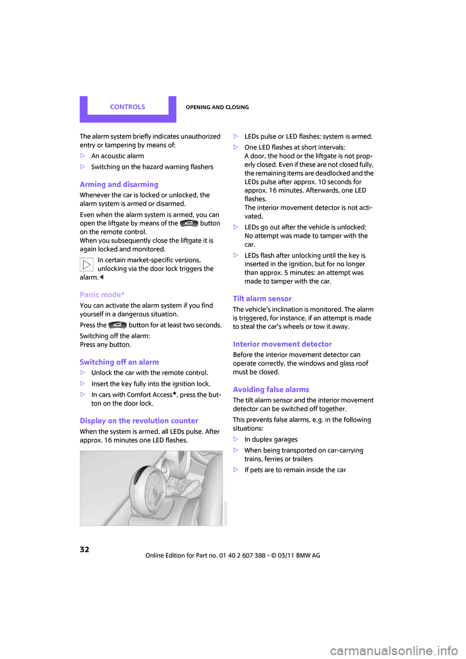
Display on the revolution counter
When the system is armed, all LEDs pulse. After
approx. 16 minutes one LED flashes. >
LEDs pulse or LED flashes: system is armed.
> One LED flashes at short intervals:
A door, the hood or the liftgate is not prop-
erly closed. Even if these are not closed fully,
the remaining items ar e deadlocked and the
LEDs pulse after approx. 10 seconds for
approx. 16 minutes. Afterwards, one LED
flashes.
The interior movement detector is not acti-
vated.
> LEDs go out after the vehicle is unlocked:
No attempt was made to tamper with the
car.
> LEDs flash after unlocking until the key is
inserted in the ignition, but for no longer
than approx. 5 minutes: an attempt was
made to tamper with the car.
Tilt alarm sensor
The vehicle's inclination is monitored. The alarm
is triggered, for instance , if an attempt is made
to steal the car's wheels or tow it away.
Interior movement detector
Before the interior movement detector can
operate correctly, the windows and glass roof
must be closed.
Avoiding false alarms
The tilt alarm sensor and the interior movement
detector can be switched off together.
This prevents false alarms, e.g. in the following
situations:
> In duplex garages
> When being transported on car-carrying
trains, ferries or trailers
> If pets are to remain inside the car
Page 36 of 256
CONTROLSOpening and closing
34
Unlocking the Split Rear Barn Doors
separately
Press the button on the outside of the Split Rear
Barn Doors.If the vehicle detects that a remote control
has been accidentally left inside the
locked vehicle's cargo area after the Split Rear
Barn Doors are closed, the Split Rear Barn Doors
will reopen slightly. The hazard warning flashers
flash and an acoustic signal
* sounds. <
Windows and glass roof, electric*
If the engine is switched off, you can still operate
the windows and glass roof so long as a door or
the Split Rear Barn Doors have not been opened.
If the doors and Split Rear Barn Doors are closed
again and the remote cont rol is located inside
the vehicle, the windows and the glass roof can
be operated again.
Insert the remote control into the ignition lock to
be able to operate the windows or glass roof
when the engine is switched off and the doors
are open.
Switching on radio readiness
Switch on radio readiness by briefly pressing the
Start/Stop button, page 46.
Do not depress the brake or the clutch;
otherwise, the engine will start. <
Starting the engine
The engine can be started or the ignition can be
switched on when a remote control is inside the
vehicle. It is not necessary to insert a remote
control into the ignition lock, page 46.
Switching off the engine in cars with
automatic transmission
The engine can only be switched off when the
selector lever is in position P, page 48.
To switch the engine off when the selector lever
is in position N, the remote control must be in
the ignition lock.
Before driving a vehicle with automatic
transmission into a car wash
1. Insert remote control into ignition lock.
2. Depress the brake.
3. Move the selector le ver to position N.
4. Switch off the engine.
The vehicle can roll.
Malfunction
Comfort Access may malf unction due to local
radio waves.
If this happens, open or close the vehicle via the
buttons on the remote control or using the inte-
grated key.
Insert the remote control into the ignition lock
and start the engine.
Warning lamps
The warning lamp lights up when an
attempt is made to start the engine: the
engine cannot be started. The remote
control is not inside the vehicle or is malfunc-
tioning. Take the remote control with you inside
the vehicle or have it checked. If necessary,
insert another remote co ntrol into the ignition
lock.
The warning lamp lights up when the
engine is running: the remote control is
no longer inside the vehicle. After the
engine is switched off, the engine can only be
restarted within approx. 10 seconds.
The indicator lamp comes on and a mes-
sage appears on the Control Display:
replace the battery in the remote con-
trol.
Replacing the battery
The remote control for Comfort Access contains
a b a t t e r y t h a t w i l l n e e d t o b e r e p l a c e d f r o m t i m e
to time.
Page 49 of 256
DrivingCONTROLS
47
Radio readiness and ignition off
All indicator and warning lamps in the displays
go out.
The ignition automatically turns off
* when the
driver's door is opened. Pressing the Start/Stop
button again switches the ignition back on.
The ignition is not switched off in situations such
as the following:
> The clutch or brake is depressed
> The low beams are switched on
Starting the engine
Do not allow the engine to run in enclosed
areas; otherwise, inhalation of the noxious
exhaust gases can lead to loss of consciousness
and death. Exhaust gases contain carbon mon-
oxide, an odorless and colorless, but highly toxic
gas. Never leave an unattended vehicle with the
engine running; otherwise, such a vehicle repre-
sents a potential safety hazard.
Before leaving the car while the engine is run-
ning, place the transmission in neutral or move
the selector lever to position P and forcefully
apply the parking brake to prevent the car from
moving. <
Avoid frequent starting in quick succes-
sion or repeated start attempts in which
the engine does not start. Otherwise, the fuel is
not burned or inadequately burned and there is
a danger of overheating and damaging the cat-
alytic converter. <
Do not let the engine warm up with the vehicle
at a standstill. Move of f immediately at a moder-
ate engine speed.
When starting the engine, do not depress the
accelerator pedal.
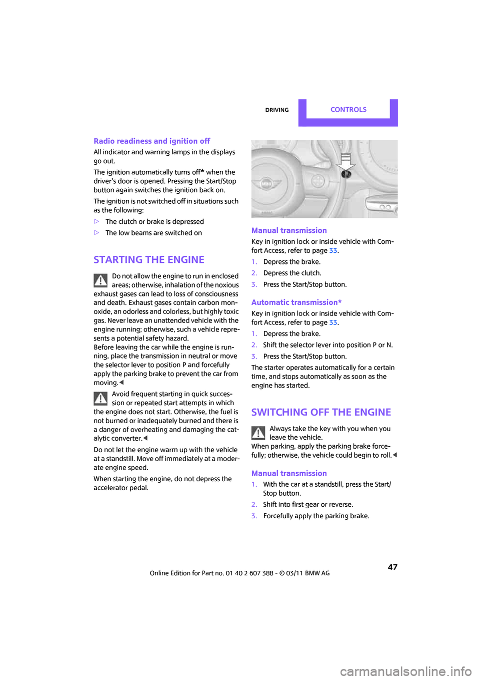
Manual transmission
Key in ignition lock or inside vehicle with Com-
fort Access, refer to page 33.
1. Depress the brake.
2. Depress the clutch.
3. Press the Start/Stop button.
Automatic transmission*
Key in ignition lock or inside vehicle with Com-
fort Access, refer to page 33.
1. Depress the brake.
2. Shift the selector lever into position P or N.
3. Press the Start/Stop button.
The starter operates auto matically for a certain
time, and stops automatically as soon as the
engine has started.
Switching off the engine
Always take the key with you when you
leave the vehicle.
When parking, apply the parking brake force-
fully; otherwise, the vehicle could begin to roll. <
Manual transmission
1.With the car at a standstill, press the Start/
Stop button.
2. Shift into first gear or reverse.
3. Forcefully apply the parking brake.
Page 57 of 256

DrivingCONTROLS
55
Display in tachometer*
Selected speed is displayed briefly.If --- mph or --- km/h is displayed briefly in
the tachometer, the conditions necessary
for operation may not be fulfilled.<
Malfunction
The warning lamp in the tachometer
lights up if the system fails. A message
appears on the Control Display.
Page 59 of 256
Controls overviewCONTROLS
57
If the range displayed is less than
30 miles/50 km, be sure to refuel; other-
wise, engine functions are not guaranteed and
damage could occur. <
With a dynamic driving st yle, e.g. rapid corner-
ing, engine functions are not always assured.
Computer*
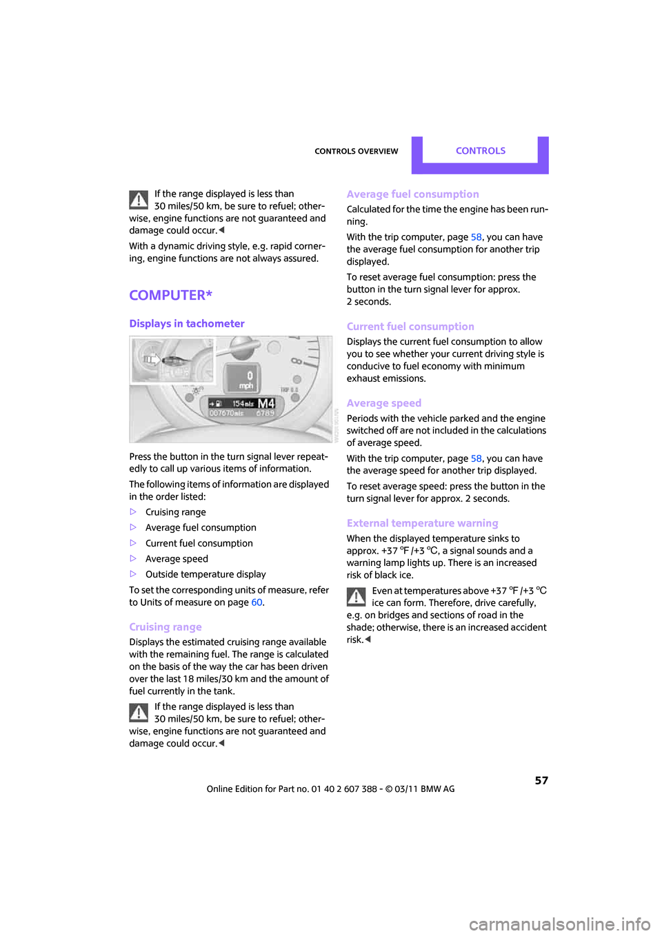
Displays in tachometer
Press the button in the turn signal lever repeat-
edly to call up various items of information.
The following items of information are displayed
in the order listed:
> Cruising range
> Average fuel consumption
> Current fuel consumption
> Average speed
> Outside temperature display
To set the corresponding units of measure, refer
to Units of measure on page 60.
Cruising range
Displays the estimated cruising range available
with the remaining fuel. The range is calculated
on the basis of the way the car has been driven
over the last 18 miles/30 km and the amount of
fuel currently in the tank.
If the range displayed is less than
30 miles/50 km, be sure to refuel; other-
wise, engine functions are not guaranteed and
damage could occur. <
Average fuel consumption
Calculated for the time the engine has been run-
ning.
With the trip computer, page 58, you can have
the average fuel consumption for another trip
displayed.
To reset average fuel consumption: press the
button in the turn signal lever for approx.
2 seconds.
Current fuel consumption
Displays the current fuel consumption to allow
you to see whether your current driving style is
conducive to fuel economy with minimum
exhaust emissions.
Average speed
Periods with the vehicle parked and the engine
switched off are not includ ed in the calculations
of average speed.
With the trip computer, page 58, you can have
the average speed for another trip displayed.
To reset average speed: press the button in the
turn signal lever for approx. 2 seconds.
External temperature warning
When the displayed temperature sinks to
approx. +37 7/+3 6, a signal sounds and a
warning lamp lights up. There is an increased
risk of black ice.
Even at temperatures above +37 7/+3 6
ice can form. Therefore, drive carefully,
e.g. on bridges and sections of road in the
shade; otherwise, there is an increased accident
risk. <