ESP MINI Clubman 2011 Owner's Manual (Mini Connected)
[x] Cancel search | Manufacturer: MINI, Model Year: 2011, Model line: Clubman, Model: MINI Clubman 2011Pages: 256, PDF Size: 3.75 MB
Page 15 of 256
CockpitAT A GLANCE
13
Indicator and warning
lamps
The concept
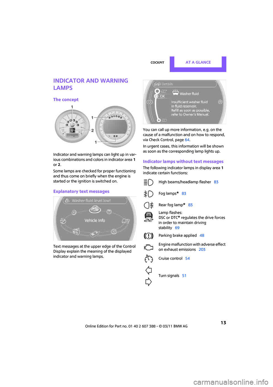
Indicator and warning lamps can light up in var-
ious combinations and colors in indicator area1
or 2.
Some lamps are checked for proper functioning
and thus come on briefly when the engine is
started or the ignition is switched on.
Explanatory text messages
Text messages at the uppe r edge of the Control
Display explain the mean ing of the displayed
indicator and warning lamps. You can call up more information, e.g. on the
cause of a malfunction and on how to respond,
via Check Control, page
64.
In urgent cases, this information will be shown
as soon as the corresponding lamp lights up.
Indicator lamps without text messages
The following indicator lamps in display area 1
indicate certain functions:
High beams/headlamp flasher 83
Fog lamps
*83
Rear fog lamp
*83
Lamp flashes:
DSC or DTC
* regulates the drive forces
in order to maintain driving
stability 69
Parking brake applied 48
Engine malfunction with adverse effect
on exhaust emissions 203
Cruise control 54
Turn signals 51
Page 23 of 256
Voice activation systemAT A GLANCE
21
Voice activation system
The concept
The voice activation system allows you to con-
trol operation of various vehicle systems without
removing your hands from the steering wheel.
Most menu items on the Control Display can be
voiced as commands. It is not necessary to use
the MINI joystick.
The voice activation sy stem transforms oral
commands into control signals for the selected
systems and provides support in the form of
instructions or questions.
Prerequisite
Via the on-board computer, select the language
in which the voice activation system is operat-
ing, so that the spoken commands can be iden-
tified. Setting the on-board computer language,
page 66.
Symbols in the Owner's Manual
Saying commands
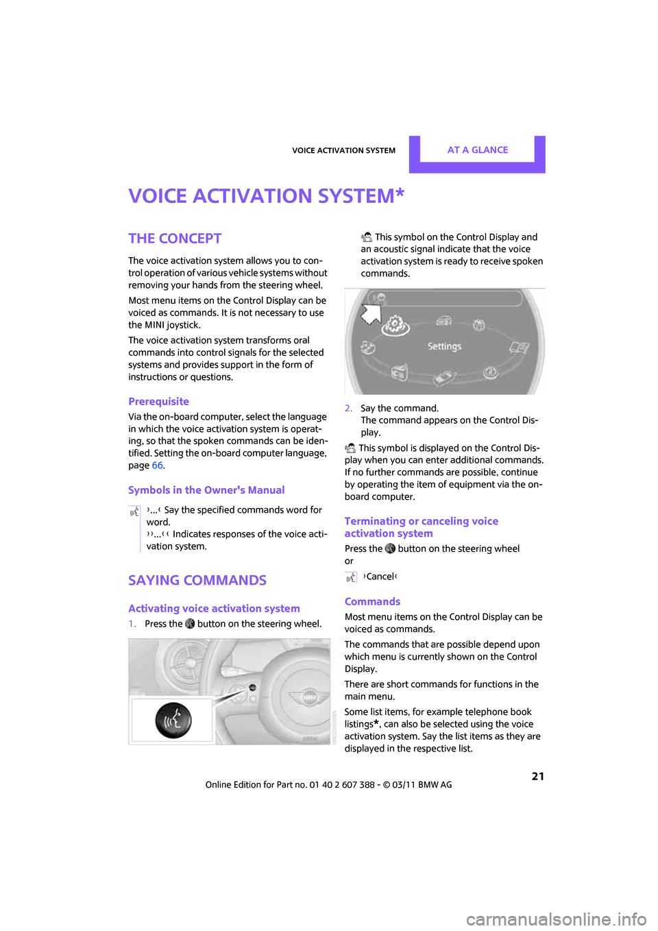
Activating voice activation system
1. Press the button on the steering wheel. This symbol on the Control Display and
an acoustic signal indicate that the voice
activation system is ready to receive spoken
commands.
2. Say the command.
The command appears on the Control Dis-
play.
This symbol is displayed on the Control Dis-
play when you can ente r additional commands.
If no further commands are possible, continue
by operating the item of equipment via the on-
board computer.
Terminating or canceling voice
activation system
Press the button on the steering wheel
or
Commands
Most menu items on the Control Display can be
voiced as commands.
The commands that are possible depend upon
which menu is currently shown on the Control
Display.
There are short commands for functions in the
main menu.
Some list items, for example telephone book
listings
*, can also be selected using the voice
activation system. Say the list items as they are
displayed in the respective list.
*
{ ...} Say the specified commands word for
word.
{{ ...}} Indicates responses of the voice acti-
vation system.
{ Cancel }
Page 24 of 256
AT A GLANCEVoice activation system
22
Having the possible commands read
aloud
Having the possible commands read aloud:
For example if you have selected "CD" the sys-
tem will read aloud the possible commands for
operating the CD player.
Help for the voice activation system
Calling up Help:
Additional commands
* for Help:
> {Help with examples }: information about
the current operating options and the most
important commands for them are
announced.
> {Help with voice activation }: information
regarding the principles behind the voice
activation system is announced.
Using alternative commands
There are often a number of commands to run a
function, e.g.:
Calling up functions immediately via
short commands
Short commands enable you to perform certain
functions immediately, irrespective of which
menu item is selected, page 230.
Open the main menu
Example: selecting the track of a CD
1.Switch on Entertainment sound output if
necessary.
2. Press the button on the steering wheel.
Setting the voice dialog
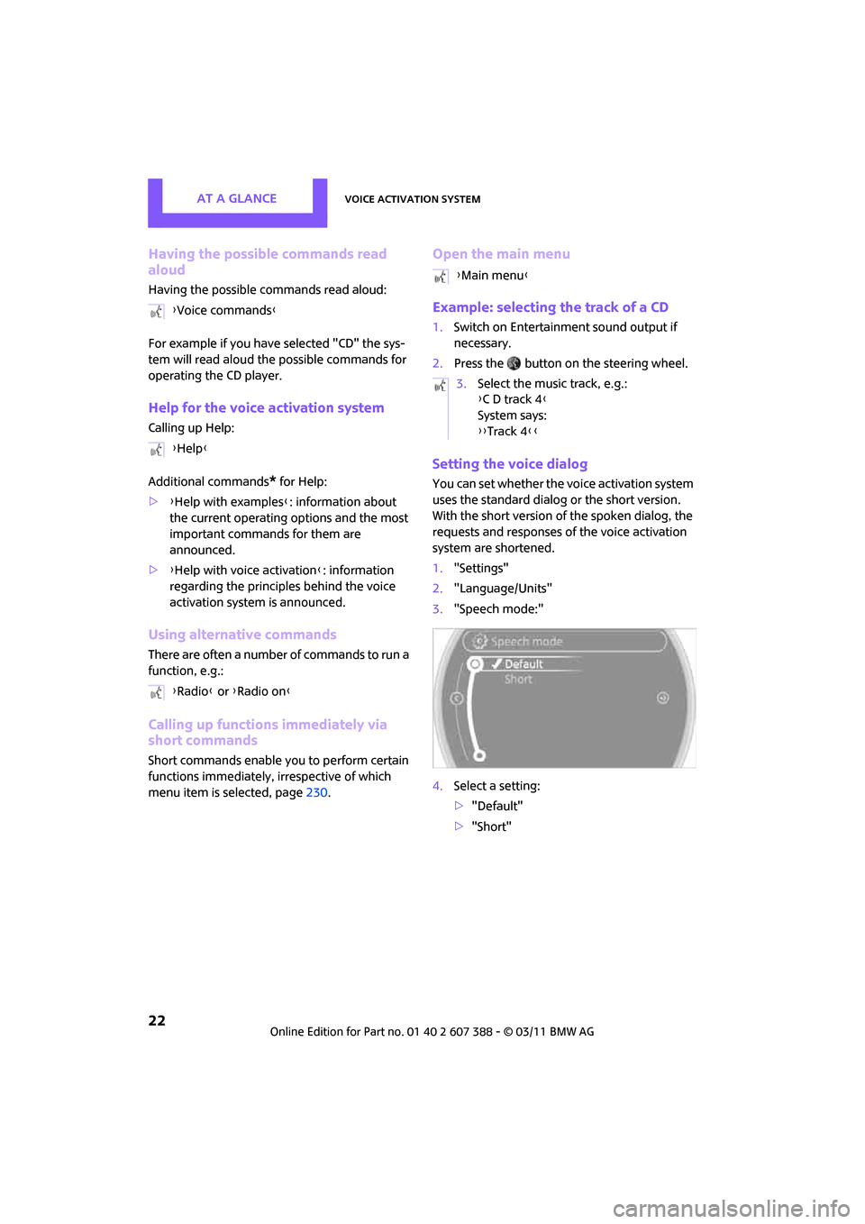
You can set whether the voice activation system
uses the standard dialog or the short version.
With the short version of the spoken dialog, the
requests and responses of the voice activation
system are shortened.
1."Settings"
2. "Language/Units"
3. "Speech mode:"
4. Select a setting:
>"Default"
> "Short"
{
Voice commands }
{ Help }
{ Radio } or {Radio on }
{Main menu }
3. Select the music track, e.g.:
{C D track 4 }
System says:
{{ Track 4 }}
Page 28 of 256
CONTROLSOpening and closing
26
Opening and closing
Keys/remote controls
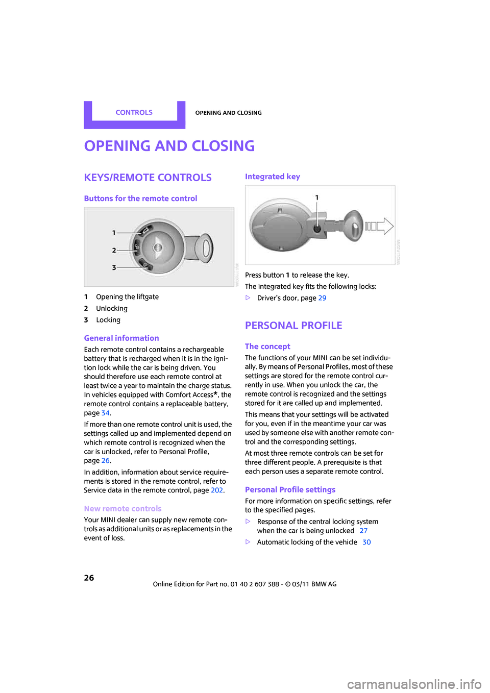
Buttons for the remote control
1Opening the liftgate
2 Unlocking
3 Locking
General information
Each remote control co ntains a rechargeable
battery that is recharged when it is in the igni-
tion lock while the car is being driven. You
should therefore use each remote control at
least twice a year to maintain the charge status.
In vehicles equipped with Comfort Access
*, the
remote control contains a replaceable battery,
page 34.
If more than one remote control unit is used, the
settings called up and implemented depend on
which remote control is recognized when the
car is unlocked, refer to Personal Profile,
page 26.
In addition, information about service require-
ments is stored in the remote control, refer to
Service data in the remote control, page 202.
New remote controls
Your MINI dealer can supply new remote con-
trols as additional units or as replacements in the
event of loss.
Integrated key
Press button1 to release the key.
The integrated key fits the following locks:
> Driver's door, page 29
Personal Profile
The concept
The functions of your MINI can be set individu-
ally. By means of Personal Profiles, most of these
settings are stored for the remote control cur-
rently in use. When you unlock the car, the
remote control is recognized and the settings
stored for it are called up and implemented.
This means that your settings will be activated
for you, even if in the meantime your car was
used by someone else with another remote con-
trol and the corresponding settings.
At most three remote co ntrols can be set for
three different people. A prerequisite is that
each person uses a se parate remote control.
Personal Profile settings
For more information on specific settings, refer
to the specified pages.
> Response of the central locking system
when the car is being unlocked 27
> Automatic locking of the vehicle 30
Page 40 of 256
CONTROLSAdjustments
38
Seats
Note before adjusting
Never attempt to adjust your seat while
the vehicle is moving. The seat could
respond with unexpected movement, and the
ensuing loss of vehicle control could lead to an
accident.
On the front passenger seat as well, do not
incline the backrest too far to the rear while the
vehicle is being driven; otherwise, there is a dan-
ger in the event of an accident of sliding under
the safety belt, eliminat ing the protection nor-
mally provided by the belt. <
Comply with the instruct ions on head restraint
height on page 39 and on damaged safety belts
on page 41.
Seat adjustment
Observe the instructions on page 38 to
ensure the best possible personal protec-
tion. <
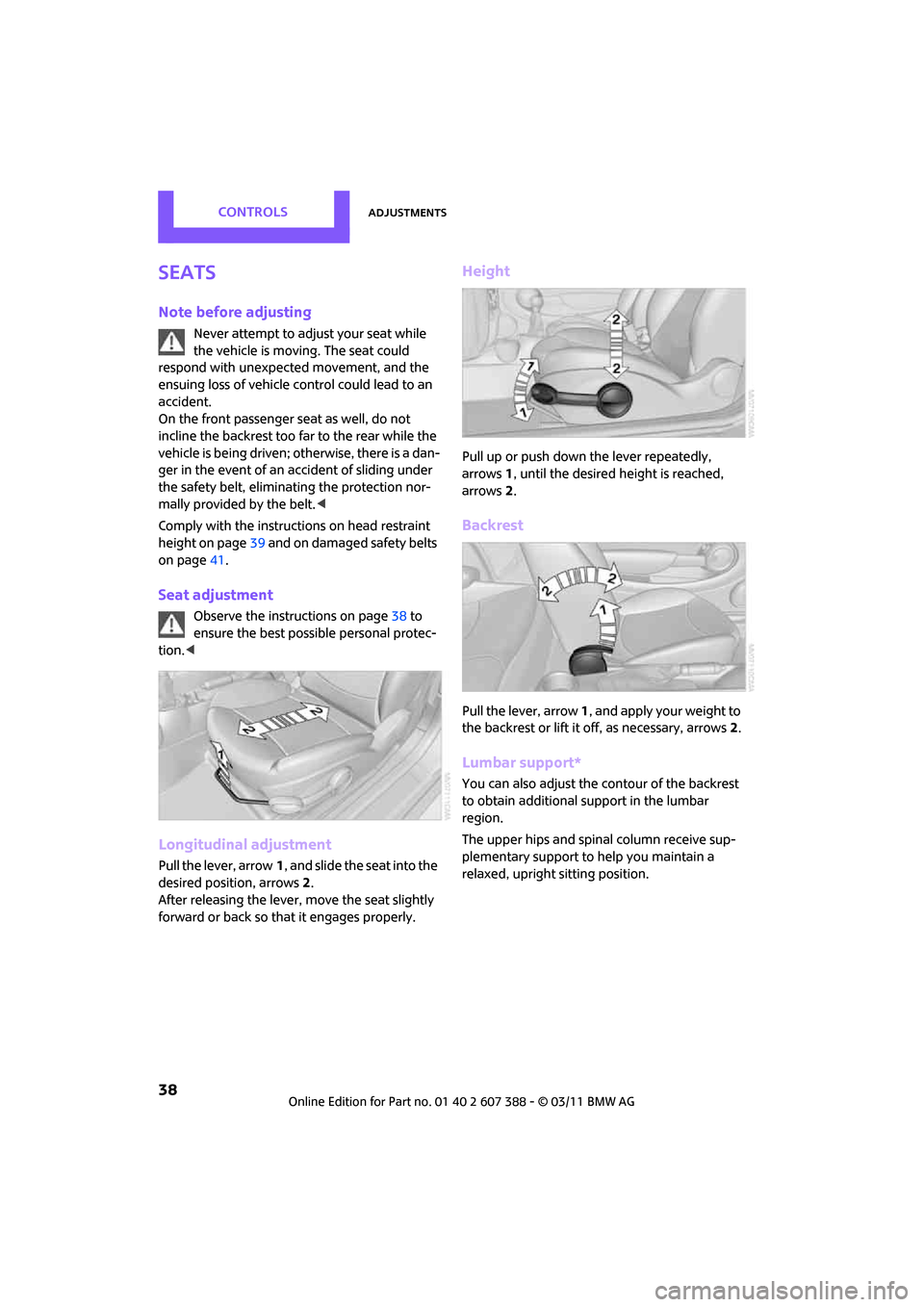
Longitudinal adjustment
Pull the lever, arrow 1, and slide the seat into the
desired position, arrows 2.
After releasing the lever, move the seat slightly
forward or back so that it engages properly.
Height
Pull up or push down the lever repeatedly,
arrows 1, until the desired he ight is reached,
arrows 2.
Backrest
Pull the lever, arrow 1, and apply your weight to
the backrest or lift it off, as necessary, arrows 2.
Lumbar support*
You can also adjust the contour of the backrest
to obtain additional support in the lumbar
region.
The upper hips and spinal column receive sup-
plementary support to help you maintain a
relaxed, upright sitting position.
Page 58 of 256
CONTROLSControls overview
56
Controls overview
Tachometer
Never operate the engine with the needle in the
red overspeed zone of the gauge. In this range,
the fuel supply is interrupted to protect the
engine.
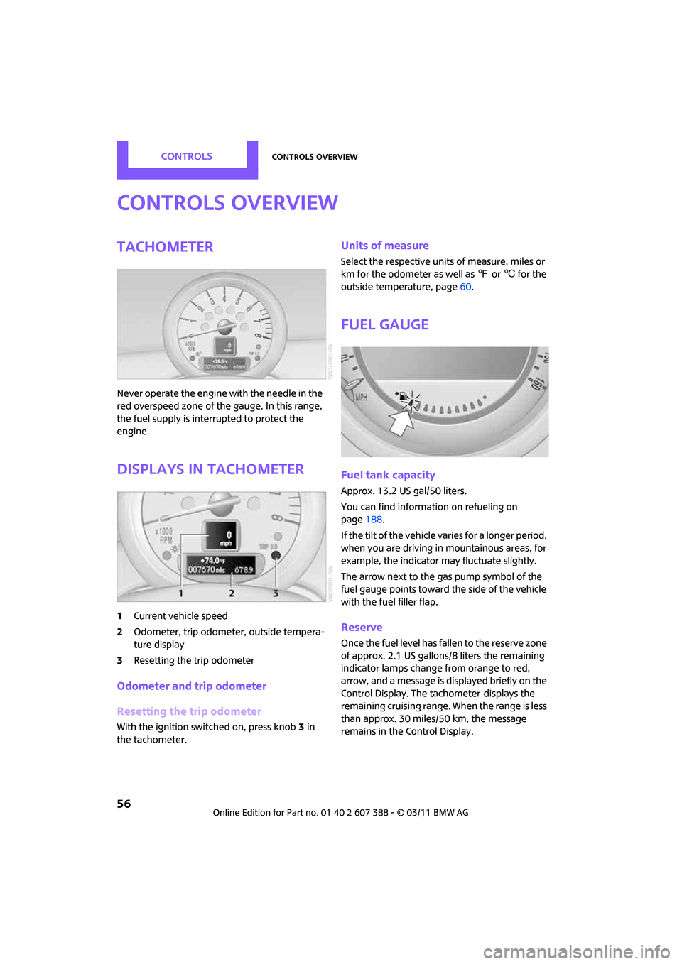
Displays in tachometer
1Current vehicle speed
2 Odometer, trip odometer, outside tempera-
ture display
3 Resetting the trip odometer
Odometer and trip odometer
Resetting the trip odometer
With the ignition switched on, press knob 3 in
the tachometer.
Units of measure
Select the respective unit s of measure, miles or
km for the odometer as well as 7 or 6 for the
outside temperature, page 60.
Fuel gauge
Fuel tank capacity
Approx. 13.2 US gal/50 liters.
You can find information on refueling on
page 188.
If the tilt of the vehicle varies for a longer period,
when you are driving in mountainous areas, for
example, the indicator may fluctuate slightly.
The arrow next to the gas pump symbol of the
fuel gauge points toward the side of the vehicle
with the fuel filler flap.
Reserve
Once the fuel level has fallen to the reserve zone
of approx. 2.1 US gallons/8 liters the remaining
indicator lamps change from orange to red,
arrow, and a message is displayed briefly on the
Control Display. The tachometer
displays the
remaining cruising range. When the range is less
than approx. 30 miles/50 km, the message
remains in the Control Display.
Page 59 of 256
Controls overviewCONTROLS
57
If the range displayed is less than
30 miles/50 km, be sure to refuel; other-
wise, engine functions are not guaranteed and
damage could occur. <
With a dynamic driving st yle, e.g. rapid corner-
ing, engine functions are not always assured.
Computer*
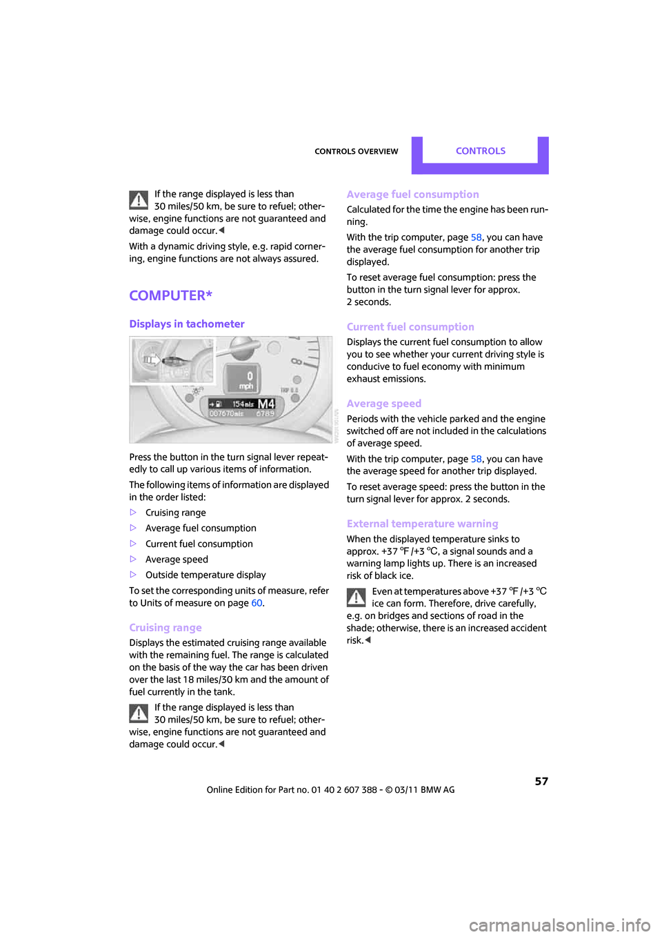
Displays in tachometer
Press the button in the turn signal lever repeat-
edly to call up various items of information.
The following items of information are displayed
in the order listed:
> Cruising range
> Average fuel consumption
> Current fuel consumption
> Average speed
> Outside temperature display
To set the corresponding units of measure, refer
to Units of measure on page 60.
Cruising range
Displays the estimated cruising range available
with the remaining fuel. The range is calculated
on the basis of the way the car has been driven
over the last 18 miles/30 km and the amount of
fuel currently in the tank.
If the range displayed is less than
30 miles/50 km, be sure to refuel; other-
wise, engine functions are not guaranteed and
damage could occur. <
Average fuel consumption
Calculated for the time the engine has been run-
ning.
With the trip computer, page 58, you can have
the average fuel consumption for another trip
displayed.
To reset average fuel consumption: press the
button in the turn signal lever for approx.
2 seconds.
Current fuel consumption
Displays the current fuel consumption to allow
you to see whether your current driving style is
conducive to fuel economy with minimum
exhaust emissions.
Average speed
Periods with the vehicle parked and the engine
switched off are not includ ed in the calculations
of average speed.
With the trip computer, page 58, you can have
the average speed for another trip displayed.
To reset average speed: press the button in the
turn signal lever for approx. 2 seconds.
External temperature warning
When the displayed temperature sinks to
approx. +37 7/+3 6, a signal sounds and a
warning lamp lights up. There is an increased
risk of black ice.
Even at temperatures above +37 7/+3 6
ice can form. Therefore, drive carefully,
e.g. on bridges and sections of road in the
shade; otherwise, there is an increased accident
risk. <
Page 60 of 256
CONTROLSControls overview
58
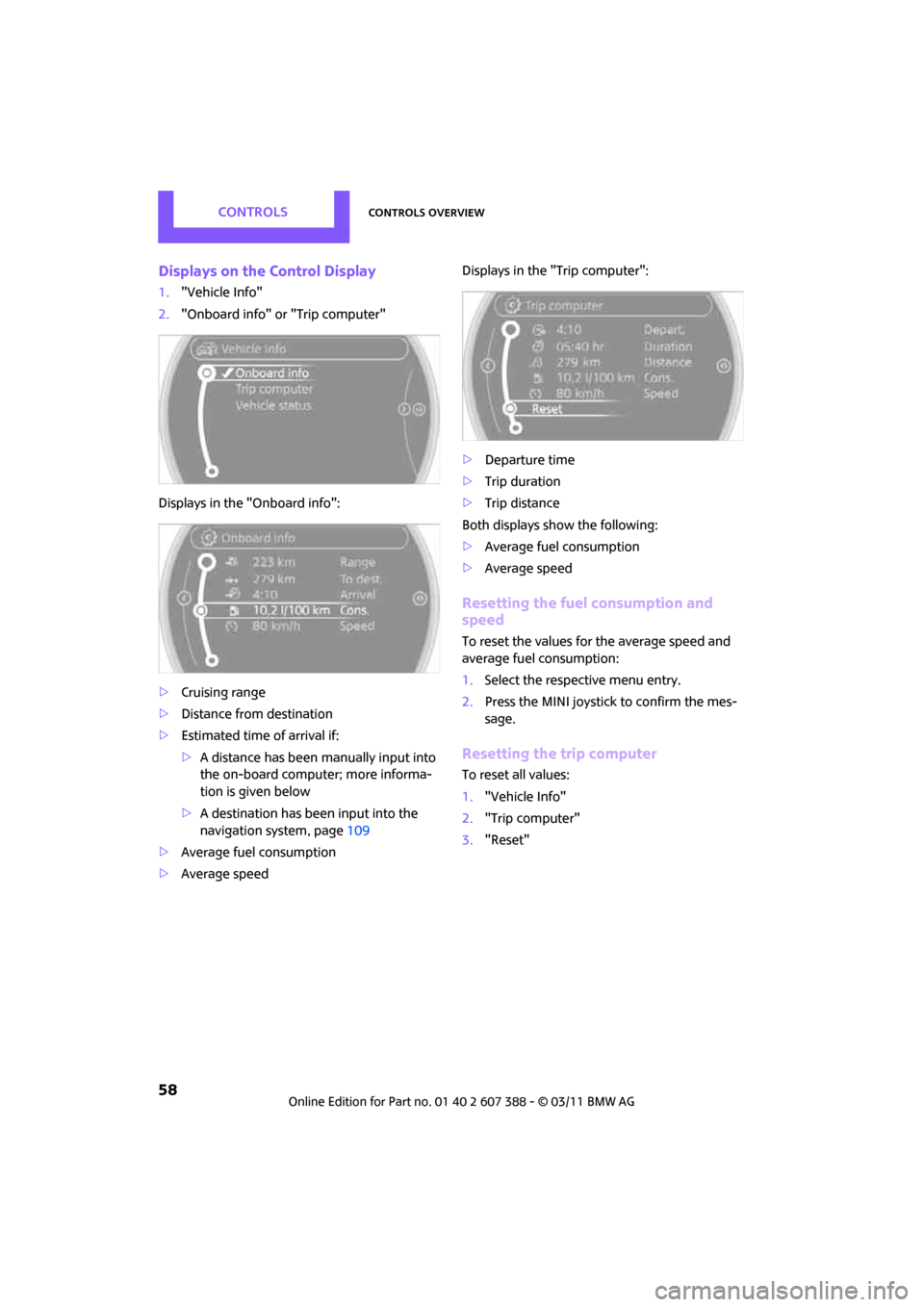
Displays on the Control Display
1."Vehicle Info"
2. "Onboard info" or "Trip computer"
Displays in the "Onboard info":
> Cruising range
> Distance from destination
> Estimated time of arrival if:
>A distance has been manually input into
the on-board computer; more informa-
tion is given below
> A destination has been input into the
navigation system, page 109
> Average fuel consumption
> Average speed Displays in the "Trip computer":
>
Departure time
> Trip duration
> Trip distance
Both displays show the following:
> Average fuel consumption
> Average speed
Resetting the fuel consumption and
speed
To reset the values for the average speed and
average fuel consumption:
1.Select the respective menu entry.
2. Press the MINI joystick to confirm the mes-
sage.
Resetting the trip computer
To reset all values:
1."Vehicle Info"
2. "Trip computer"
3. "Reset"
Page 66 of 256
CONTROLSControls overview
64
Check Control
The concept
The Check Control monitors vehicle functions
and alerts you to any malfunctions in the sys-
tems monitored. Check Control messages
involve indicator and warning lamps in the dis-
play and, in some circumstances, an acoustic
signal as well as text messages at the bottom of
the Control Display.
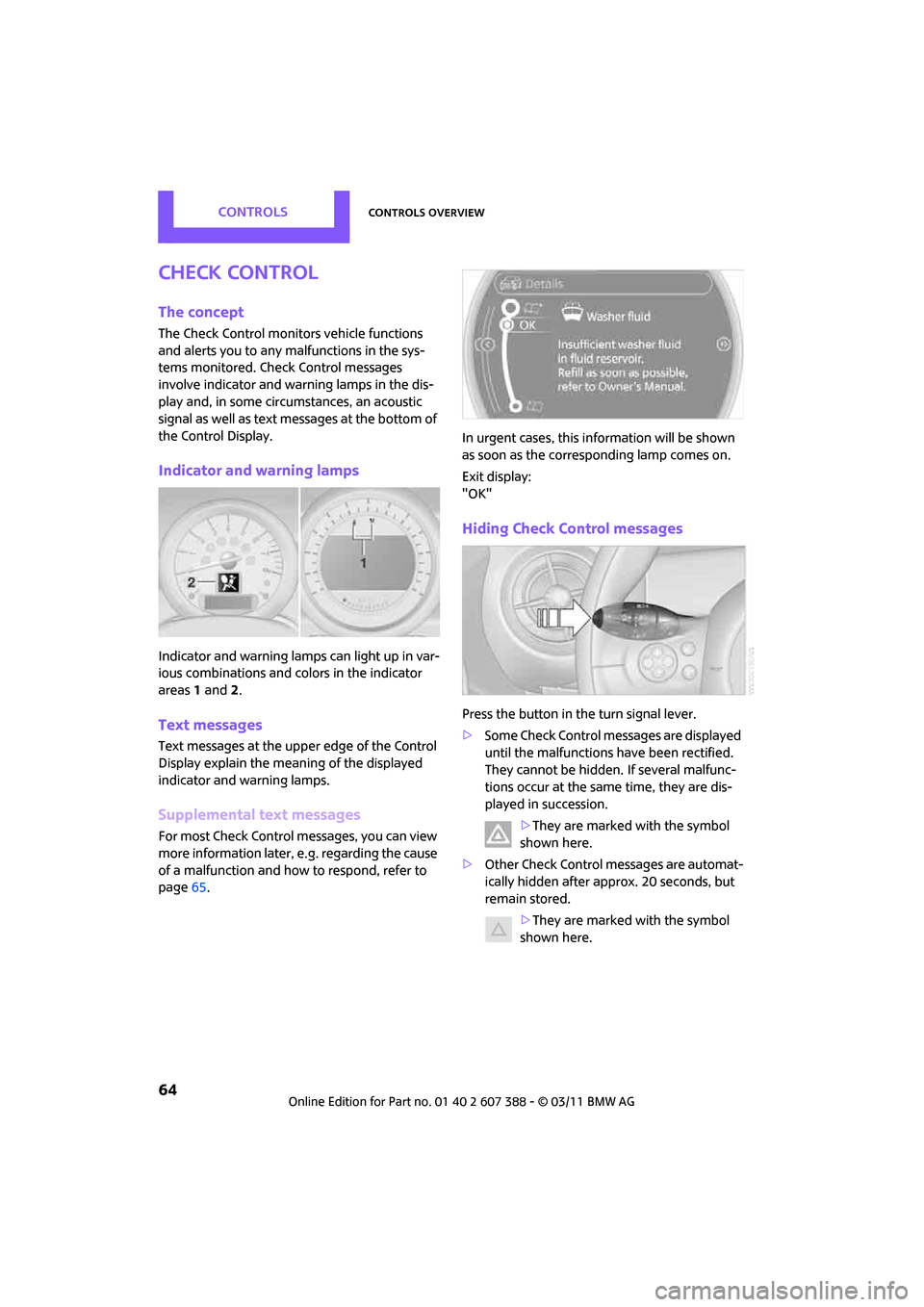
Indicator and warning lamps
Indicator and warning lamps can light up in var-
ious combinations and colors in the indicator
areas 1 and 2.
Text messages
Text messages at the uppe r edge of the Control
Display explain the mean ing of the displayed
indicator and warning lamps.
Supplemental text messages
For most Check Control messages, you can view
more information later, e.g. regarding the cause
of a malfunction and how to respond, refer to
page 65. In urgent cases, this information will be shown
as soon as the corresponding lamp comes on.
Exit display:
"OK"
Hiding Check Control messages
Press the button in th
e turn signal lever.
> Some Check Control messages are displayed
until the malfunctions have been rectified.
They cannot be hidden. If several malfunc-
tions occur at the same time, they are dis-
played in succession.
>They are marked with the symbol
shown here.
> Other Check Control messages are automat-
ically hidden after approx. 20 seconds, but
remain stored.
>They are marked with the symbol
shown here.
Page 67 of 256
Controls overviewCONTROLS
65
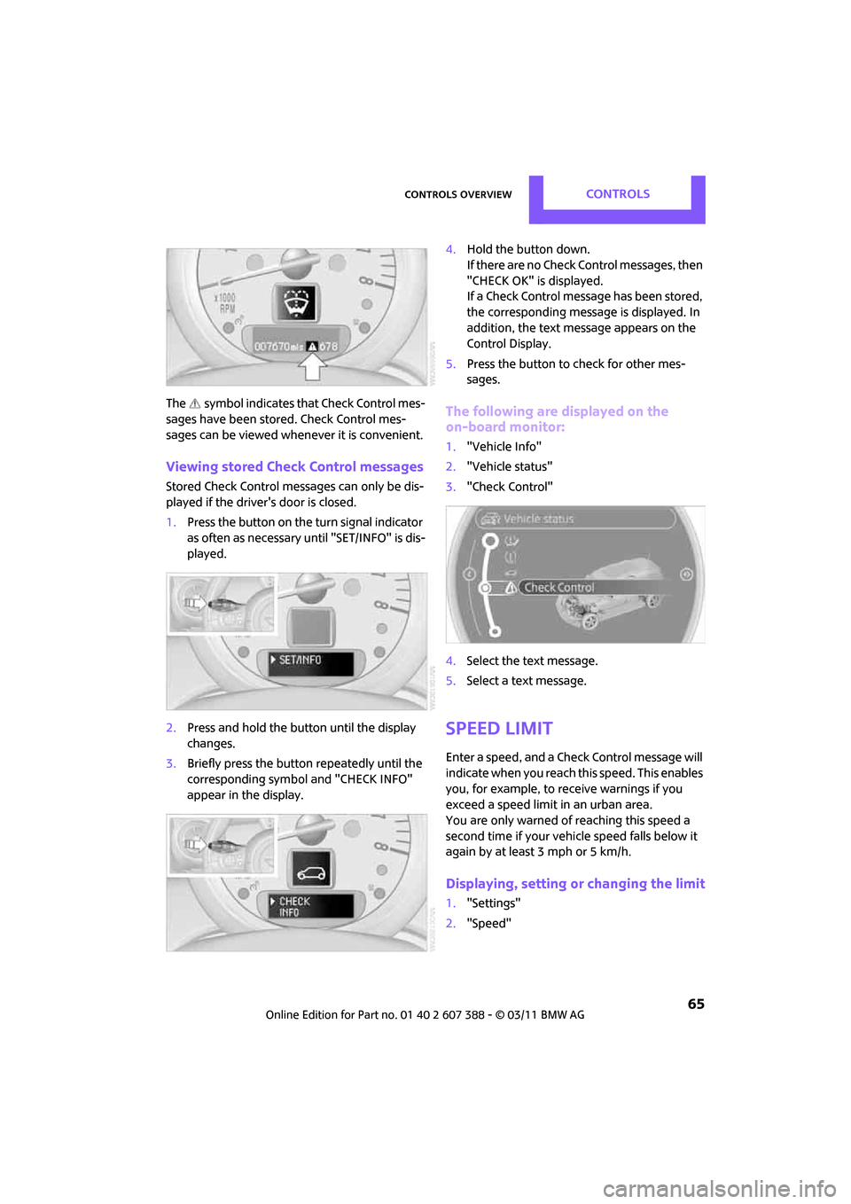
The symbol indicates that Check Control mes-
sages have been stored. Check Control mes-
sages can be viewed when ever it is convenient.
Viewing stored Check Control messages
Stored Check Control messages can only be dis-
played if the driver's door is closed.
1.Press the button on the turn signal indicator
as often as necessary until "SET/INFO" is dis-
played.
2. Press and hold the butt on until the display
changes.
3. Briefly press the button repeatedly until the
corresponding symbol and "CHECK INFO"
appear in the display. 4.
Hold the button down.
If there are no Check Control messages, then
"CHECK OK" is displayed.
If a Check Control messa ge has been stored,
the corresponding message is displayed. In
addition, the text message appears on the
Control Display.
5. Press the button to check for other mes-
sages.
The following are displayed on the
on-board monitor:
1."Vehicle Info"
2. "Vehicle status"
3. "Check Control"
4. Select the text message.
5. Select a text message.
Speed limit
Enter a speed, and a Check Control message will
indicate when you reach this speed. This enables
you, for example, to receive warnings if you
exceed a speed limit in an urban area.
You are only warned of reaching this speed a
second time if your vehicle speed falls below it
again by at least 3 mph or 5 km/h.
Displaying, setting or changing the limit
1. "Settings"
2. "Speed"