check engine MINI Clubman 2014 User Guide
[x] Cancel search | Manufacturer: MINI, Model Year: 2014, Model line: Clubman, Model: MINI Clubman 2014Pages: 210, PDF Size: 5.12 MB
Page 153 of 210

If the inflation pressure of 1.8 bar/26 psi is still
not reached, the tire is too heavily damaged.
Contact the nearest service center.
Stowing the Mobility System1.Unscrew the filling hose 2 of the sealant
bottle from the wheel.2.Unscrew the compressor connection hose 6
from the sealant bottle.3.Connect the filling hose 2 of the sealant
bottle with the free connector on the seal‐
ant bottle.
This prevents left-over sealant from escap‐
ing from the bottle.4.Wrap the empty sealant bottle in suitable
material to avoid dirtying the cargo area.5.Stow the Mobility System back in the vehi‐
cle.
Distributing the sealant
Drive approx. 3.1 miles/5 km to evenly distrib‐
ute the sealant.
Do not exceed a speed of 50 mph/80 km/h. If
possible, do not drop below a speed of
10 mph/20 km/h.
Correcting the tire inflation pressure
1.After driving approx. 3.1 miles/5 km, or
about 10 minutes, stop in a suitable loca‐
tion.2.Screw the connection hose 6 of the com‐
pressor directly onto the tire valve.3.Insert the connector 5 into the power
socket in the passenger compartment.4.Correct the tire inflation pressure to
1.8 bar/26 psi. When the engine is running:▷To increase the inflation pressure:
switch on the compressor. To check the
currently set inflation pressure, switch
off the compressor.▷To reduce the inflation pressure: press
the release button 9.Do not allow the compressor to run too
long
Do not allow the compressor to run longer than
10 minutes; otherwise, the device will overheat
and may be damaged. ◀
If the inflation pressure is not maintained, take
the vehicle on another drive, distributing the
sealant, refer to page 153. Then repeat steps
1 to 4 once.
If the inflation pressure of 1.8 bar/26 psi is still
not reached, the tire is too heavily damaged.
Contact the nearest service center.
Continuing the trip Note the maximum speed
Do not exceed the maximum speed of
50 mph/80 km/h; otherwise, accidents can oc‐
cur. ◀
Replace the defective tire as soon as possible
and have the wheel balanced.
Have the Mobility System refilled.
Snow chains
Only certain fine-link snow chains have been
tested by MINI, classified as safe for use, and
recommended. Consult your service center for more information.
Use only in pairs on the front wheels, equipped
with tires of the following size:▷175/65 R 15 M+S▷175/60 R 16 M+S
John Cooper Works:
▷185/50 R 17 86 H M+S XL RSC
Observe the manufacturer's instructions when
mounting snow chains. Do not exceed a speed
of 30 mph or 50 km/h when using snow chains.
Do not initialize the Flat Tire Monitor if snow
chains are mounted; otherwise, the instrument
might issue an incorrect reading. When driving
with snow chains, it may be useful to tempora‐
Seite 153Wheels and tiresMobility153
Online Edition for Part no. 01 40 2 911 429 - VI/13
Page 157 of 210
Engine oilVehicle equipment
This chapter describes all series equipment as
well as country-specific and special equipment
offered for this model series.Therefore, it also
describes equipment that may not be found in
your vehicle, for instance due to the selected
special equipment or the country version. This
also applies to safety-related functions and sys‐
tems.
Engine oil General information
Engine oil consumption depends on the driving
style and the conditions of use. A highly sporty
driving style, for example, results in considera‐
bly higher engine oil consumption.
Therefore, regularly check the engine oil level
after refueling.
Checking the oil level with a dip stick1.Park the vehicle on level ground when the
engine is at operating temperature, i.e., af‐
ter driving continuously for at least
6 2 miles/10 km.2.Switch the engine off.3.After approx. 5 minutes, pull out the dip
stick and wipe it off with a lint-free cloth,
paper towel, etc.4.Carefully insert the dip stick all the way into
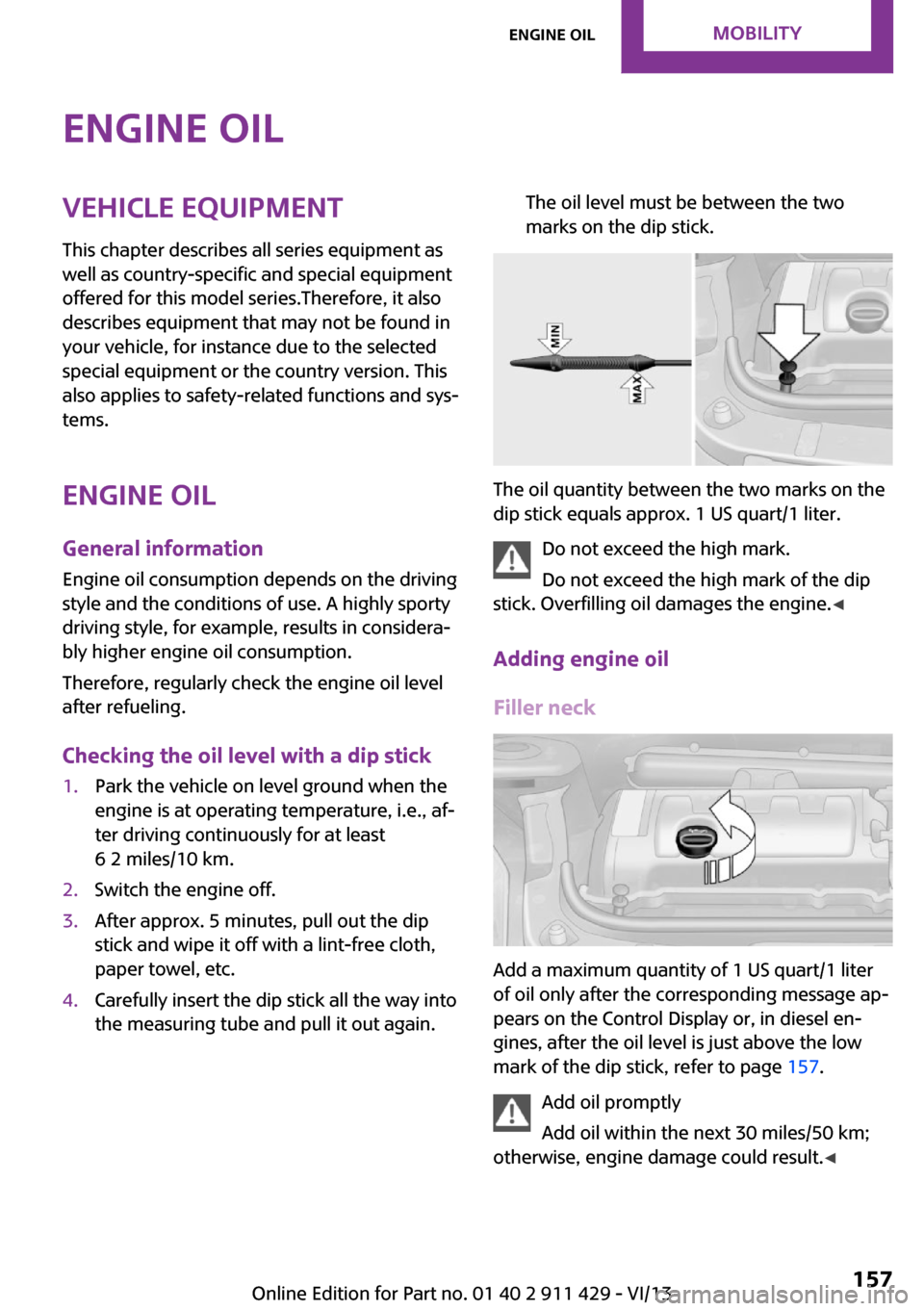
the measuring tube and pull it out again.The oil level must be between the two
marks on the dip stick.
The oil quantity between the two marks on the
dip stick equals approx. 1 US quart/1 liter.
Do not exceed the high mark.
Do not exceed the high mark of the dip
stick. Overfilling oil damages the engine. ◀
Adding engine oil
Filler neck
Add a maximum quantity of 1 US quart/1 liter
of oil only after the corresponding message ap‐
pears on the Control Display or, in diesel en‐
gines, after the oil level is just above the low
mark of the dip stick, refer to page 157.
Add oil promptly
Add oil within the next 30 miles/50 km;
otherwise, engine damage could result. ◀
Seite 157Engine oilMobility157
Online Edition for Part no. 01 40 2 911 429 - VI/13
Page 158 of 210

Too much engine oil
Have the vehicle checked immediately;
otherwise, surplus oil can lead to engine dam‐
age. ◀
Protect children
Keep oil, grease, etc., out of reach of chil‐
dren and heed the warnings on the containers
to prevent health risks. ◀
Oil types for refilling
Notes No oil additives
Do not use oil additives as these may
cause engine damage. ◀
Viscosity classes of engine oils
When selecting an engine oil, ensure that
the engine oil belongs to one of the SAE viscos‐
ity classes 0W-40, 0W-30, 5W-40, or 5W-30, or
malfunctions or engine damage may occur. ◀
The engine oil quality is critical for the life of the
engine.
Due to national regulations, some oil types are
not available in every country.
Approved oil typesGasoline engineBMW High Performance SAE 5W-30BMW Longlife-01BMW Longlife-01 FE
Further information on approved oil types can
be obtained from the service center.
Alternative oil types
If the approved engine oils are not available, up
to 1 US quart/1 liter of an oil with the following
specification can be used:
Gasoline engineAPI SM or a higher quality standard
Oil change
An oil change should be carried out by the serv‐
ice center only.
Seite 158MobilityEngine oil158
Online Edition for Part no. 01 40 2 911 429 - VI/13
Page 159 of 210
CoolantVehicle equipment
This chapter describes all series equipment as
well as country-specific and special equipment
offered for this model series.Therefore, it also
describes equipment that may not be found in
your vehicle, for instance due to the selected
special equipment or the country version. This
also applies to safety-related functions and sys‐
tems.
General information Danger of burns from hot engine
Do not open the cooling system while the
engine is hot; otherwise, escaping coolant may
cause burns. ◀
Suitable additives
Only use suitable additives; otherwise,
engine damage may occur. The additives are
harmful to your health. ◀
Coolant consists of water and additives.
Not all commercially available additives are
suitable for your MINI vehicle. Ask your service
center for suitable additives.
Coolant temperature
If the coolant and therefore the engine over‐
heat, a warning lamp lights up, refer to
page 183.
Coolant level
Checking1.Do not open the hood until the engine has
cooled down.2.Turn the expansion tank cap counterclock‐
wise slightly to allow any accumulated
pressure to escape; then continue turning
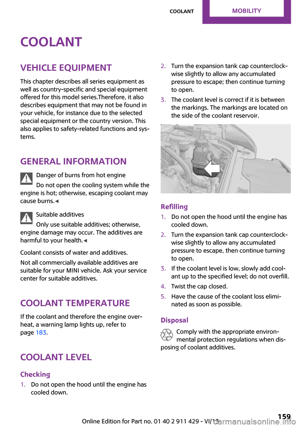
to open.3.The coolant level is correct if it is between
the markings. The markings are located on
the side of the coolant reservoir.
Refilling
1.Do not open the hood until the engine has
cooled down.2.Turn the expansion tank cap counterclock‐
wise slightly to allow any accumulated
pressure to escape, then continue turning
to open.3.If the coolant level is low, slowly add cool‐
ant up to the specified level; do not overfill.4.Twist the cap closed.5.Have the cause of the coolant loss elimi‐
nated as soon as possible.
Disposal
Comply with the appropriate environ‐mental protection regulations when dis‐
posing of coolant additives.
Seite 159CoolantMobility159
Online Edition for Part no. 01 40 2 911 429 - VI/13
Page 161 of 210

Socket for OBD Onboard
Diagnosis
Socket for Onboard Diagnosis
The socket for Onboard Diagnosis may
only be used by the service center, by work‐
shops that operate according to the specifica‐
tions of the vehicle manufacturer with appro‐
priately trained personnel, and by other
authorized persons. Otherwise, its use may
lead to vehicle malfunctions. ◀
Primary components in the vehicle emissions
can be checked via the OBD socket using a de‐
vice.
Emissions The warning lamps light up. The vehicle
is producing higher emissions. You can
continue your journey, but moderate
your speed and exercise due caution. Have the
vehicle checked as soon as possible.
Under certain circumstances, one of the lamps
flashes or lights up continuously. This indicates
that there is excessive misfiring or a malfunc‐
tion in the engine. If this happens, reduce the
vehicle speed and drive to the next service cen‐
ter promptly. Serious engine misfiring within a
brief period can seriously damage emission
control components, in particular the catalytic
converter. In addition, the mechanical engine
components may become damaged.
If the fuel filler cap is not properly tight‐
ened, the OBD system may conclude
that fuel vapor is escaping; this will cause a dis‐
play to light up. If the filler cap is then tight‐
ened, the display should go out in a few days.Seite 161MaintenanceMobility161
Online Edition for Part no. 01 40 2 911 429 - VI/13
Page 165 of 210
rates after a short time. The headlamps do not
need to be changed.
If the condensation in the headlamps does not
evaporate after trips with the lights switched
on, and the amount of moisture in the head‐
lamps increases, for example if water droplets
form, have them checked by your service cen‐
ter.
Bi-xenon headlamps These bulbs have a very long life and the likeli‐
hood of failure is very low, provided that they
are not switched on and off excessively. If a
bulb should nevertheless fail, you can continue
driving cautiously with the front fog lamps, pro‐
vided this is permitted by local laws.
Do not perform work/bulb replacement
on xenon headlamps
Have any work on the xenon lighting system,
including bulb replacement, performed only by
a service center.
Due to the high voltage present in the system,
there is the danger of fatal injuries if work is
carried out improperly. ◀
Front lamps, bulb replacement
Halogen low beams and high beams
Bulb H13, 60/55 watt
Wear protective goggles and gloves
Halogen bulbs are pressurized. Therefore,
wear protective goggles and gloves. Otherwise,
there is a danger of injuries if the bulb is acci‐
dentally damaged during replacement. ◀
Attach the cover carefully
When attaching the cover, proceed care‐
fully; otherwise, leaks may occur, causing dam‐
age to the headlamp system. ◀Access to the bulbs through the engine
compartment
Follow the general instructions on lamps and
bulbs, refer to page 164.
Low beam/high beam bulbs can be changed
from the engine compartment.
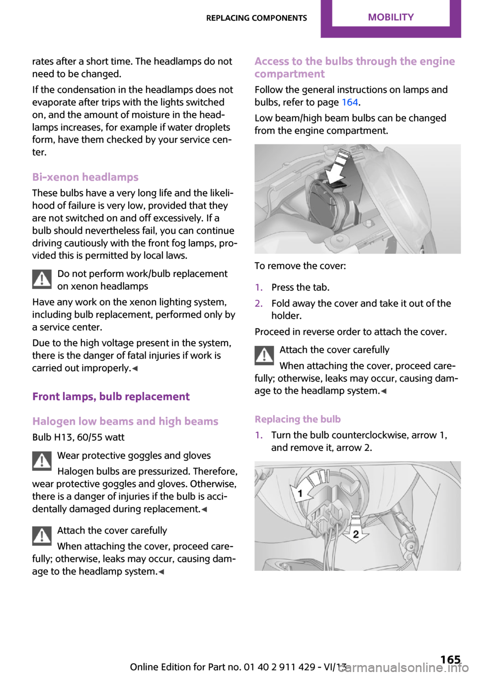
To remove the cover:
1.Press the tab.2.Fold away the cover and take it out of the
holder.
Proceed in reverse order to attach the cover.
Attach the cover carefully
When attaching the cover, proceed care‐
fully; otherwise, leaks may occur, causing dam‐
age to the headlamp system. ◀
Replacing the bulb
1.Turn the bulb counterclockwise, arrow 1,
and remove it, arrow 2.Seite 165Replacing componentsMobility165
Online Edition for Part no. 01 40 2 911 429 - VI/13
Page 171 of 210
11.Unscrew the valve extension from the valve
of the compact wheel.12.Unscrew the dust cap from the extension
and attach it to the valve of the compact
wheel.
The defective wheel cannot be stowed in the
compact wheel holder because it has a differ‐
ent size.
MINI Clubman: removing the compact
wheel
The compact wheel is located under the wheel
change set in the cargo area.
1.Fold up the floor mat.2.Unscrew the nut, arrow, and take out the
compact wheel.
Driving with compact wheel
Do not exceed a speed of
50 mph/80 km/h.
Drive conservatively and do not exceed a speed
of 50 mph/80 km/h. Otherwise, changes in the
driving characteristics could result, for example
reduced track stability on braking, extended
braking distance, and altered self-steering
characteristics in the limit range. In conjunction
with winter tires, these characteristics are more
pronounced. ◀
Only mount one compact wheel
Only one compact wheel may be
mounted. Restore the wheels and tires to their
original size as quickly as possible. Failure to do
so is a safety risk. ◀
Check the tire inflation pressure at the next op‐
portunity and correct it if necessary. Replace
the defective tire as soon as possible and have
the new wheel balanced.
Preparing wheel change
Observe the safety precautions regarding flat
tires, refer to page 151.
Additional safety precautions in the event
of a wheel change
Change the wheel only on a level, firm surface
which is not slippery.
The vehicle or the jack could slip to the side if
you attempt to raise the vehicle on a soft or
slippery surface, snow, ice, tiles, etc. Do not use
a wooden block or similar object as a support
base for the jack, as this would prevent it from
extending to its full support height and reduce
its load-carrying capacity.
To avoid serious or fatal injury: never lie under
the vehicle, and never start the engine while it
is supported by the jack. ◀1.Place the folding wheel chock behind the
front wheel of the other vehicle side; if the
vehicle is on an incline, place it in front of
this wheel. If the vehicle is parked on a
steep incline, additionally secure the vehi‐
cle against rolling.2.Expose the lug bolts if necessary.3.Loosen the lug bolts a half turn.
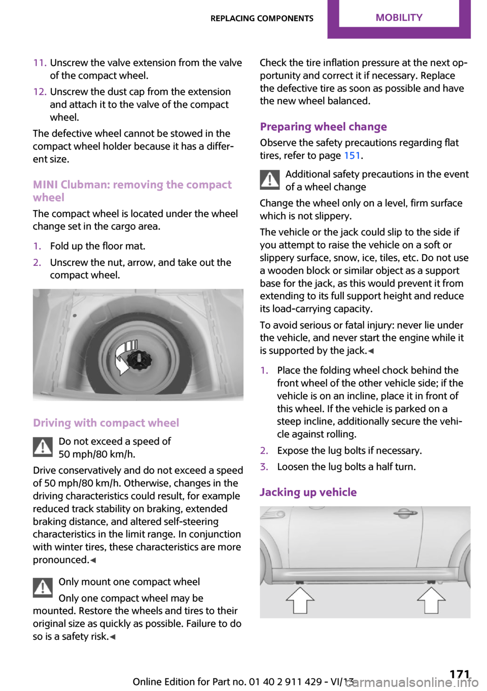
Jacking up vehicle
Seite 171Replacing componentsMobility171
Online Edition for Part no. 01 40 2 911 429 - VI/13
Page 175 of 210

MINI Clubman
The first aid kit is located in the left side trim on
the cargo area floor or under the flat loading
floor.
Roadside Assistance
Service availability Roadside Assistance can be reached around the
clock in many countries. You can obtain assis‐
tance there in the event of a vehicle break‐
down.
Roadside Assistance A phone number for Roadside Assistance can
be displayed, refer to page 132, via the radio.
Jump-starting NotesIf the battery is discharged, the engine can be
started using the battery of another vehicle and
two jumper cables. In the same way, you can
help jump-start another vehicle. Only use
jumper cables with fully insulated clamp han‐
dles.
To prevent personal injury or damage to both
vehicles, adhere strictly to the following proce‐
dure.
Do not touch live parts
To avoid the risk of potentially fatal injury,
always avoid all contact with electrical compo‐
nents while the engine is running. ◀
Preparation1.Check whether the battery of the other ve‐
hicle has a voltage of 12 volts and approxi‐
mately the same capacitance in Ah. This in‐
formation can be found on the battery.2.Switch off the engine of the assisting vehi‐
cle.3.Switch off any electronic systems/power
consumers in both vehicles.
Bodywork contact between vehicles
There must not be any contact between
the bodies of the two vehicles, otherwise there
is a danger of shorting. ◀
Seite 175Breakdown assistanceMobility175
Online Edition for Part no. 01 40 2 911 429 - VI/13
Page 176 of 210

Connecting jumper cablesConnecting order
Connect the jumper cables in the correct
order; otherwise, there is the danger of injury
from sparking. ◀1.Open the battery cover in the engine com‐
partment to access the positive terminal.2.Unlock the tabs of the positive terminal
cover on the left and right, arrows 1, and
raise the cover, arrow 2.3.Attach one terminal clamp of the positive
jumper cable to the positive terminal of the
battery or to a starting aid terminal of the
vehicle providing assistance.4.Attach the second clamp of the positive
jumper cable to the positive terminal of the
battery of the vehicle to be started.5.Attach one terminal clamp of the negative
jumper cable to the negative terminal of
the battery, or to the corresponding engine
or body ground of the vehicle providing as‐
sistance.6.Attach the second clamp of the negative
jumper cable to the negative terminal ofthe battery, or to the engine or body
ground of the vehicle to be started.
Body ground:
Starting the engine
Never use spray fluids to start the engine.
1.Start the engine of the assisting vehicle and
let it run for several minutes at a slightly in‐
creased idle speed.2.Start the engine of the vehicle being started
in the usual way.
If the first starting attempt is not successful,
wait a few minutes before making another
attempt in order to allow the discharged
battery to recharge.3.Let both engines run for several minutes.4.Disconnect the jumper cables in the reverse
order.
Check the battery and recharge if necessary.
Tow-starting and towing
Notes Observe applicable laws and regulations
Observe applicable laws and regulations
for tow-starting and towing. ◀
No additional passengers
Do not transport any passengers other
than the driver in a vehicle that is being
towed. ◀
Seite 176MobilityBreakdown assistance176
Online Edition for Part no. 01 40 2 911 429 - VI/13
Page 178 of 210
Manual transmission
Gearshift lever in neutral position.
Automatic transmission Towing vehicles with an automatic trans‐
mission
Only transport vehicles with an automatic
transmission on tow trucks or with raised front
wheels; otherwise, the transmission may be
damaged. ◀
Towing with a tow bar Light towing vehicle
The towing vehicle must not be lighter
than your vehicle, or it will not be possible to
control vehicle response. ◀
Correctly attach the tow bar
Only secure the tow bar on the tow fit‐
tings; damage can occur when it is secured on
other parts of the vehicle. ◀
The tow fittings used should be on the same
side on both vehicles.
Should it prove impossible to avoid mounting
the tow bar at an offset angle, please observe
the following:▷Clearance and maneuvering capability will
be sharply limited during cornering.▷The tow bar will generate lateral forces if it
is attached offset.
Towing with a tow rope
When starting to tow the vehicle, make sure
that the tow rope is taut.
To avoid jerking and the associated stresses on
the vehicle components when towing, always
use nylon ropes or nylon straps.
Attaching the tow rope correctly
Only secure the tow rope on the tow fit‐
ting; otherwise, damage can occur when it is
secured on other parts of the vehicle. ◀
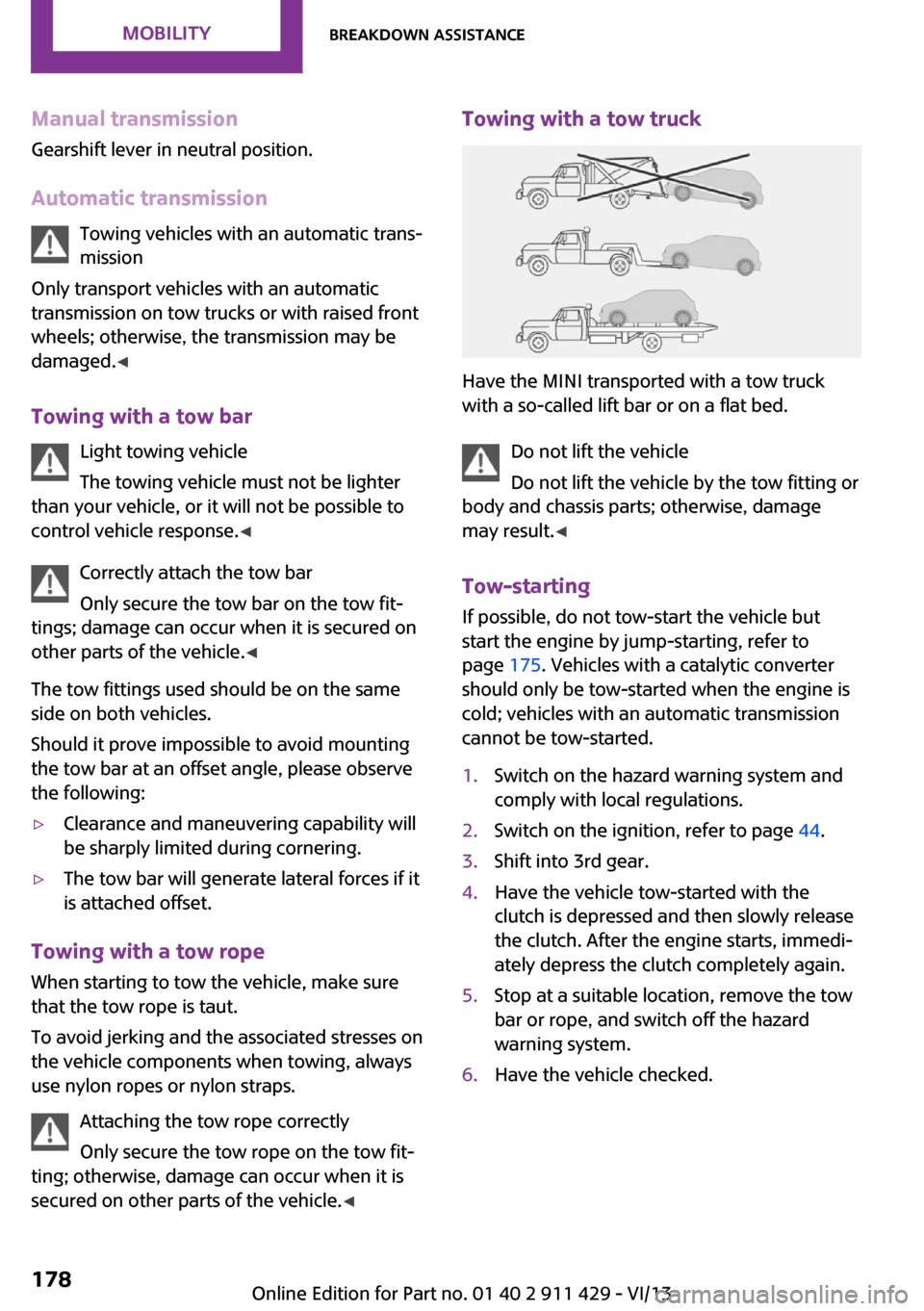
Towing with a tow truck
Have the MINI transported with a tow truck
with a so-called lift bar or on a flat bed.
Do not lift the vehicle
Do not lift the vehicle by the tow fitting or
body and chassis parts; otherwise, damage
may result. ◀
Tow-starting
If possible, do not tow-start the vehicle but
start the engine by jump-starting, refer to
page 175. Vehicles with a catalytic converter
should only be tow-started when the engine is
cold; vehicles with an automatic transmission
cannot be tow-started.
1.Switch on the hazard warning system and
comply with local regulations.2.Switch on the ignition, refer to page 44.3.Shift into 3rd gear.4.Have the vehicle tow-started with the
clutch is depressed and then slowly release
the clutch. After the engine starts, immedi‐
ately depress the clutch completely again.5.Stop at a suitable location, remove the tow
bar or rope, and switch off the hazard
warning system.6.Have the vehicle checked.Seite 178MobilityBreakdown assistance178
Online Edition for Part no. 01 40 2 911 429 - VI/13