ESP MINI Clubman 2016 (Mini Connected) Manual Online
[x] Cancel search | Manufacturer: MINI, Model Year: 2016, Model line: Clubman, Model: MINI Clubman 2016Pages: 246, PDF Size: 5.21 MB
Page 199 of 246
CoolantVehicle features and op‐
tions
This chapter describes all standard, country-
specific and optional features offered with the
series. It also describes features that are not
necessarily available in your car, e. g., due to
the selected options or country versions. This
also applies to safety-related functions and sys‐
tems. The respectively applicable country provi‐
sions must be observed when using the respec‐
tive features and systems.
Information
WARNING
With the engine hot and the cooling sys‐
tem open, coolant can escape and lead to
burns. There is risk of injuries. Only open the
cooling system with the engine cooled down.◀
WARNING
Additives are harmful and incorrect addi‐
tives can damage the engine. There is risk of in‐
juries and risk of property damage. Avoid the
contact of articles of clothing, skin or eyes with
additives. Do not swallow any additives. Use
suitable additives only.◀
Coolant consists of water and additives.
Not all commercially available additives are
suitable for the vehicle. Information about suit‐
able additives is available from a dealer’s serv‐
ice center or another qualified service center or
repair shop.
Coolant level
Overview
Open the hood, refer to page 193.
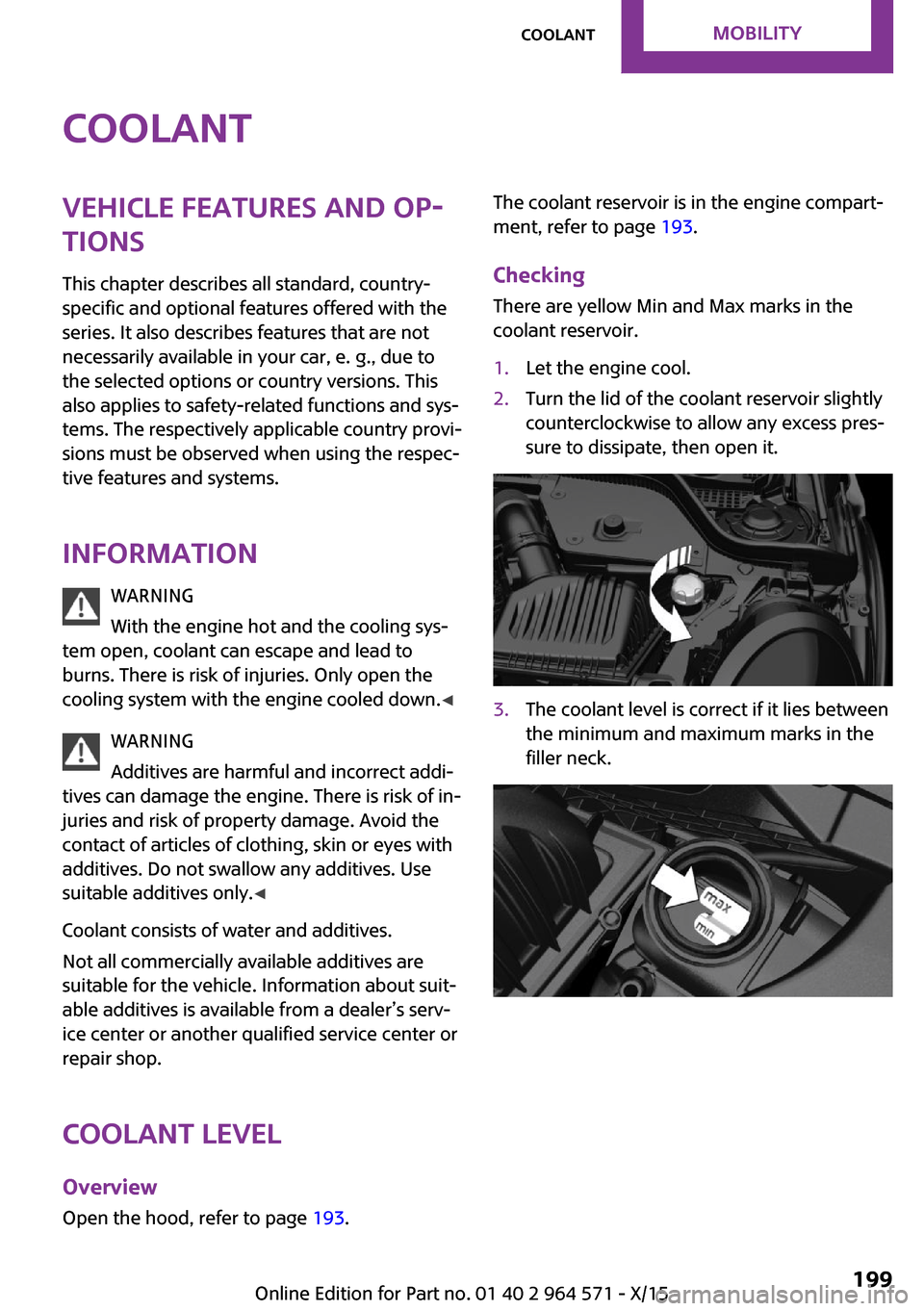
The coolant reservoir is in the engine compart‐
ment, refer to page 193.
Checking
There are yellow Min and Max marks in the
coolant reservoir.
1.Let the engine cool.2.Turn the lid of the coolant reservoir slightly
counterclockwise to allow any excess pres‐
sure to dissipate, then open it.
3.The coolant level is correct if it lies between
the minimum and maximum marks in the
filler neck.
Seite 199CoolantMOBILITY199
Online Edition for Part no. 01 40 2 964 571 - X/15
Page 201 of 246

MaintenanceVehicle features and op‐
tions
This chapter describes all standard, country-
specific and optional features offered with the
series. It also describes features that are not
necessarily available in your car, e. g., due to
the selected options or country versions. This
also applies to safety-related functions and sys‐
tems. The respectively applicable country provi‐
sions must be observed when using the respec‐
tive features and systems.
MINI maintenance system
The maintenance system indicates required
maintenance measures, and thereby provides
support in maintaining road safety and the op‐
erational reliability of the vehicle.
In some cases scopes and intervals may vary
according to the country-specific version. Re‐
placement work, spare parts, fuels and lubri‐
cants and wear materials are calculated sepa‐
rately. Further information is available from a
dealer’s service center or another qualified
service center or repair shop.
Condition Based Service
CBS
Sensors and special algorithms take into ac‐
count the driving conditions of your vehicle.
Based on this, Condition Based Service recog‐
nizes the maintenance requirements.
The system makes it possible to adapt the
amount of maintenance corresponding to your
user profile.
Detailed information on service requirements,
refer to page 85, can be displayed on the Con‐
trol Display.
Service data in the remote control
Information on the required maintenance is
continuously stored in the remote control. The
dealer’s service center can read this data out
and suggest an optimized maintenance scope
for your vehicle.
Therefore, hand the service advisor the remote
control with which the vehicle was driven most
recently.
Storage periods
Storage periods during which the vehicle bat‐
tery was disconnected are not taken into ac‐
count.
If this occurs, have a dealer's service center or
another qualified service center or repair shop
update the time-dependent maintenance pro‐
cedures, such as checking brake fluid and, if
necessary, changing the engine oil and the mi‐
crofilter/activated-charcoal filter.
Service and Warranty In‐
formation Booklet for
US models and Warranty
and Service Guide Book‐
let for Canadian models
Please consult your Service and Warranty Infor‐
mation Booklet for US models and Warranty
and Service Guide Booklet for Canadian models
for additional information on service require‐
ments.
The manufacturer of your vehicle recommends
that maintenance and repair be performed by a
dealer’s service center or another qualified
Seite 201MaintenanceMOBILITY201
Online Edition for Part no. 01 40 2 964 571 - X/15
Page 203 of 246
Replacing componentsVehicle features and op‐
tions
This chapter describes all standard, country-
specific and optional features offered with the
series. It also describes features that are not
necessarily available in your car, e. g., due to
the selected options or country versions. This
also applies to safety-related functions and sys‐
tems. The respectively applicable country provi‐
sions must be observed when using the respec‐
tive features and systems.
Onboard vehicle tool kit
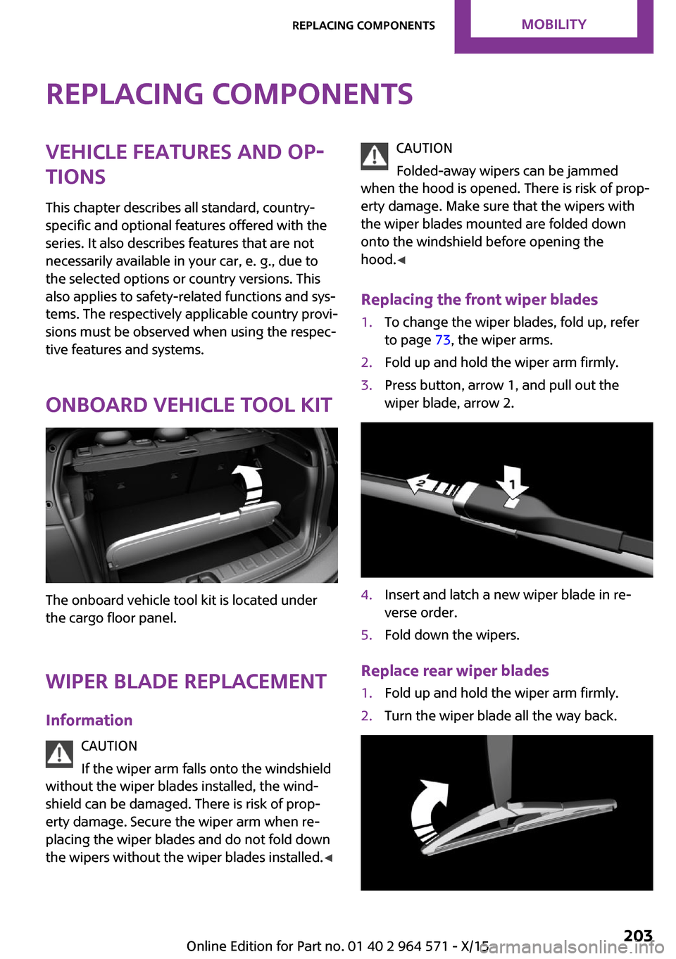
The onboard vehicle tool kit is located under
the cargo floor panel.
Wiper blade replacement
Information
CAUTION
If the wiper arm falls onto the windshield
without the wiper blades installed, the wind‐
shield can be damaged. There is risk of prop‐
erty damage. Secure the wiper arm when re‐
placing the wiper blades and do not fold down
the wipers without the wiper blades installed.◀
CAUTION
Folded-away wipers can be jammed
when the hood is opened. There is risk of prop‐
erty damage. Make sure that the wipers with
the wiper blades mounted are folded down
onto the windshield before opening the
hood.◀
Replacing the front wiper blades
1.To change the wiper blades, fold up, refer
to page 73, the wiper arms.
2.Fold up and hold the wiper arm firmly.3.Press button, arrow 1, and pull out the
wiper blade, arrow 2.
4.Insert and latch a new wiper blade in re‐
verse order.
5.Fold down the wipers.
Replace rear wiper blades
1.Fold up and hold the wiper arm firmly.2.Turn the wiper blade all the way back.Seite 203Replacing componentsMOBILITY203
Online Edition for Part no. 01 40 2 964 571 - X/15
Page 204 of 246

3.Continue turning the wiper blade all the
way so that it pops out of the holder.
4.Press the new wiper blade into the holder
until you hear it snap into place.
5.Fold the wipers in.
Lamp and bulb replace‐
ment
General information
Lights and bulbs make an essential contribution
to vehicle safety.
The manufacturer of the vehicle recommends
that you have appropriate work performed by a
dealer’s service center or another qualified
service center or repair shop if you are unfami‐
liar with it or if it has not been described here.
A spare lamp box is available from a dealer’s
service center or another qualified service cen‐
ter or repair shop.
Information
Lights and bulbs
WARNING
Bulbs can get hot during operation. Con‐
tact with the bulbs can cause burns. There is
risk of injuries. Only change bulbs after they
have cooled off.◀
WARNING
Work on switched-on lighting systems
can cause short circuits. There is risk of injuries
or risk of property damage. When working on
the lighting system, switch off the lamps in
question. If necessary, heed the bulb manufac‐
turer's instructions.◀
CAUTION
Dirty bulbs have a reduced service life.
There is risk of property damage. Do not hold
new bulbs with your bare hands. Use a clean
cloth or something similar, or hold the bulb by
its base.◀
Light-emitting diodes (LEDs)
Some items of equipment use light-emitting di‐
odes installed behind a cover as a light source.
These light-emitting diodes, which are related
to conventional lasers, are officially designated
as Class 1 light-emitting diodes.
WARNING
Too intensive brightness can irritate or
damage the retina of the eye. There is risk of
injuries. Do not look directly into the headlights
or other light sources. Do not remove the LED
covers.◀
Headlight glass
Condensation can form on the inside of the ex‐
ternal lights in cool or humid weather. When
driving with the lights switched on, the conden‐
sation evaporates after a short time. The head‐
light glass does not need to be changed.
If despite driving with the lights switched on,
increasing humidity forms, e. g. water droplets
in the lamp, the manufacturer of your vehicle
recommends having it checked by a dealer’s
service center or another qualified service cen‐
ter or repair shop.
Seite 204MOBILITYReplacing components204
Online Edition for Part no. 01 40 2 964 571 - X/15
Page 207 of 246
LED parking lights/LED fog lights
Follow the general instructions on lights and
bulbs, refer to page 204.
The lights feature LED technology. In the case
of a malfunction, contact a dealer’s service cen‐
ter or another qualified service center or repair
shop.
Parking lights/fog lights/daytime
running lights
Follow the general instructions on lights and
bulbs, refer to page 204.
Bulbs:
▷Parking lights for halogen headlights: W5W
Parking lights for LED headlights: W5W NBV
▷Daytime running light: PSX24W▷Fog lamp: H8
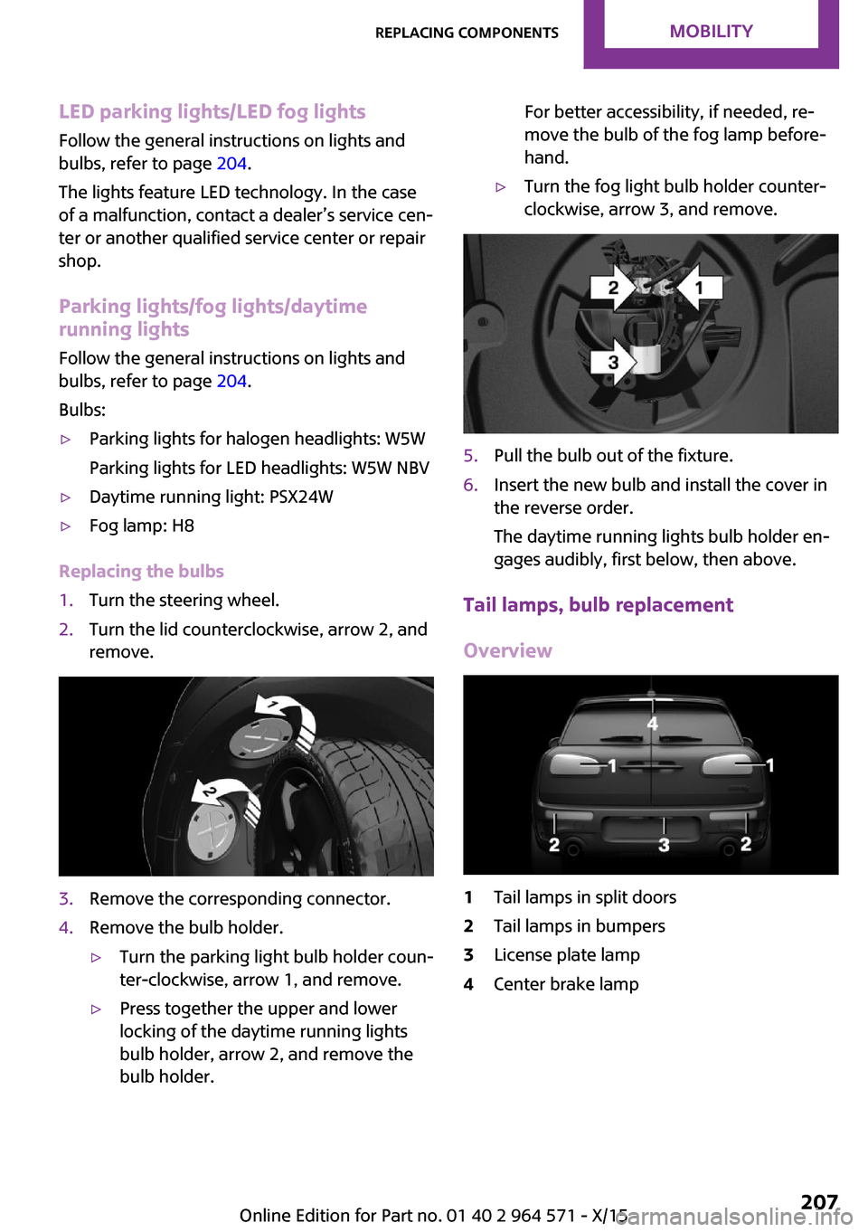
Replacing the bulbs
1.Turn the steering wheel.2.Turn the lid counterclockwise, arrow 2, and
remove.
3.Remove the corresponding connector.4.Remove the bulb holder.▷Turn the parking light bulb holder coun‐
ter-clockwise, arrow 1, and remove.
▷Press together the upper and lower
locking of the daytime running lights
bulb holder, arrow 2, and remove the
bulb holder.
For better accessibility, if needed, re‐
move the bulb of the fog lamp before‐
hand.
▷Turn the fog light bulb holder counter-
clockwise, arrow 3, and remove.
5.Pull the bulb out of the fixture.6.Insert the new bulb and install the cover in
the reverse order.
The daytime running lights bulb holder en‐
gages audibly, first below, then above.
Tail lamps, bulb replacement
Overview
1Tail lamps in split doors2Tail lamps in bumpers3License plate lamp4Center brake lampSeite 207Replacing componentsMOBILITY207
Online Edition for Part no. 01 40 2 964 571 - X/15
Page 216 of 246

Breakdown assistanceVehicle features and op‐
tions
This chapter describes all standard, country-
specific and optional features offered with the
series. It also describes features that are not
necessarily available in your car, e. g., due to
the selected options or country versions. This
also applies to safety-related functions and sys‐
tems. The respectively applicable country provi‐
sions must be observed when using the respec‐
tive features and systems.
Hazard warning flash‐
ers
The button is located above the Control Dis‐
play.
Warning triangle
Depending on the equipment version, the
warning triangle is located in the cargo area or
under the cargo floor panel.
First-aid kit
The first-aid kit is located in the trunk.
Some of the articles have a limited service life.
Check the expiration dates of the contents reg‐
ularly and replace any expired items promptly.
Jump-starting
General information
If the battery is discharged, the engine can be
started using the battery of another vehicle and
two jumper cables. Only use jumper cables with
fully insulated clamp handles.
Information
DANGER
Contact with live components can lead to
an electric shock. There is risk of injuries or
danger to life. Do not touch any components
that are under voltage.◀
To prevent personal injury or damage to both
vehicles, adhere strictly to the following proce‐
dure.
Preparation
CAUTION
In the case of body contact between the
two vehicles, a short circuit can occur during
jump-starting. There is risk of property damage.
Make sure that no body contact occurs.◀
1.Check whether the battery of the other ve‐
hicle has a voltage of 12 volts. The voltage
information can be found on the battery.
2.Switch off the engine of the assisting vehi‐
cle.
3.Switch off any electronic systems/power
consumers in both vehicles.
Seite 216MOBILITYBreakdown assistance216
Online Edition for Part no. 01 40 2 964 571 - X/15
Page 217 of 246

Starting aid terminals
WARNING
If the jumper cables are connected in the
incorrect order, sparks formation can occur.
There is risk of injuries. Pay attention to the cor‐
rect order during connection.◀
The starting aid terminal in the engine com‐
partment acts as the battery's positive terminal.
Open the cover of the starting aid terminal.
The body ground or a special nut acts as the
battery negative terminal.
Connecting the cables
1.Pull off the lid of the starting aid terminal.2.Attach one terminal clamp of the positive
jumper cable to the positive terminal of the
battery, or to the corresponding starting aid
terminal of the vehicle providing assistance.
3.Attach the terminal clamp on the other end
of the cable to the positive terminal of the
battery, or to the corresponding starting aid
terminal of the vehicle to be started.
4.Attach one terminal clamp of the negative
jumper cable to the negative terminal of
the battery, or to the corresponding engine
or body ground of assisting vehicle.
5.Attach the second terminal clamp to the
negative terminal of the battery, or to the
corresponding engine or body ground of
the vehicle to be started.
Starting the engine
Never use spray fluids to start the engine.
1.Start the engine of the assisting vehicle and
let it run for several minutes at an increased
idle speed.
2.Start the engine of the vehicle that is to be
started in the usual way.
If the first starting attempt is not successful,
wait a few minutes before making another
attempt in order to allow the discharged
battery to recharge.
3.Let both engines run for several minutes.4.Disconnect the jumper cables in the reverse
order.
Check the battery and recharge if needed.
Tow-starting and towing
Information
WARNING
Due to system limits, individual functions
can malfunction during tow-starting/towing
with the Intelligent Safety systems activated,
for example approach control warning with
light braking function. There is risk of an acci‐
dent. Switch all Intelligent Safety systems off
prior to tow-starting/towing.◀
Switching off Intelligent Safety systems, refer to
page 110.
Seite 217Breakdown assistanceMOBILITY217
Online Edition for Part no. 01 40 2 964 571 - X/15
Page 220 of 246
▷Use only the tow fitting provided with the
vehicle and screw it all the way in.
▷Use the tow fitting for towing on paved
roads only.
▷Use tow fitting located in the front only for
positioning the vehicle.
▷Avoid lateral loading of the tow fitting, for
example, do not lift the vehicle by the tow
fitting.
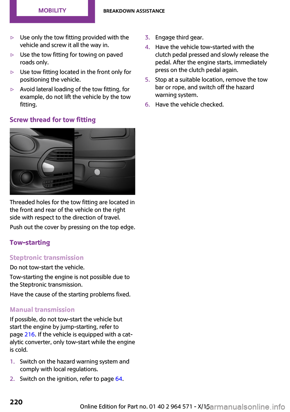
Screw thread for tow fitting
Threaded holes for the tow fitting are located in
the front and rear of the vehicle on the right
side with respect to the direction of travel.
Push out the cover by pressing on the top edge.
Tow-starting
Steptronic transmission
Do not tow-start the vehicle.
Tow-starting the engine is not possible due to
the Steptronic transmission.
Have the cause of the starting problems fixed.
Manual transmission
If possible, do not tow-start the vehicle but
start the engine by jump-starting, refer to
page 216. If the vehicle is equipped with a cat‐
alytic converter, only tow-start while the engine
is cold.
1.Switch on the hazard warning system and
comply with local regulations.
2.Switch on the ignition, refer to page 64.3.Engage third gear.4.Have the vehicle tow-started with the
clutch pedal pressed and slowly release the
pedal. After the engine starts, immediately
press on the clutch pedal again.
5.Stop at a suitable location, remove the tow
bar or rope, and switch off the hazard
warning system.
6.Have the vehicle checked.Seite 220MOBILITYBreakdown assistance220
Online Edition for Part no. 01 40 2 964 571 - X/15
Page 221 of 246
CareVehicle features and op‐
tions
This chapter describes all standard, country-
specific and optional features offered with the
series. It also describes features that are not
necessarily available in your car, e. g., due to
the selected options or country versions. This
also applies to safety-related functions and sys‐
tems. The respectively applicable country provi‐
sions must be observed when using the respec‐
tive features and systems.
Car washes
General information
Regularly remove foreign objects such as leaves
in the area below the windshield when the
hood is raised.
Wash your vehicle frequently, particularly in
winter. Intense soiling and road salt can dam‐
age the vehicle.
Steam jets or high-pressure washers
Information
CAUTION
When cleaning with high-pressure wash‐
ers, components can be damaged due to the
pressure or temperatures being too high. There
is risk of property damage. Maintain sufficient
distance and do not spray too long continu‐
ously. Follow the Owner's Manual for the high-
pressure washer.◀
Distances and temperature
▷Maximum temperature: 140 ℉/60 ℃.▷Minimum distance from sensors, cameras,
seals: 12 inches/30 cm.
▷Minimum distance from glass sunroof:
31.5 inches/80 cm.
Automatic car washes
Information
CAUTION
Improper use of automatic car washes
can cause damage to the vehicle. There is risk
of property damage. Information the following
instructions:
▷Give preference to cloth car washes or
those that use soft brushes in order to
avoid paint damage.
▷Avoid car washes with guide rails higher
than 4 in/10 cm to avoid damage to the
chassis.
▷Observe the tire width of the guide rail to
avoid damage to tires and rims.
▷Fold in exterior mirrors to avoid damage to
the exterior mirrors.
▷Unscrew the rod antenna to avoid the rod
antenna breaking off.
▷Deactivate rain sensor if necessary to avoid
damage to the wiper system.◀
In some cases, an unintentional alarm can be
triggered by the interior motion sensor of the
alarm system. Follow the instructions on avoid‐
ing an unintentional alarm, refer to page 45.
With front PDC: to reduce PDC false alarms,
switch off automatic PDC activation on obstacle
detection, for example in car washes, refer to
page 129.
Before driving into a car wash
In order to ensure that the vehicle can roll in a
car wash, take the following steps:
Seite 221CareMOBILITY221
Online Edition for Part no. 01 40 2 964 571 - X/15
Page 223 of 246

wear and premature degradation of the leather
surface.
To guard against discoloration, such as from
clothing, clean leather and provide leather care
roughly every two months.
Clean light-colored leather more frequently be‐
cause soiling on such surfaces is substantially
more visible.
Use leather care products; otherwise, dirt and
grease will gradually break down the protective
layer of the leather surface.
Suitable care products are available from a
dealer’s service center or another qualified
service center or repair shop.
Upholstery material care
Vacuum regularly with a vacuum cleaner.
If upholstery is very dirty, for example, with
beverage stains, use a soft sponge or micro‐
fiber cloth with a suitable interior cleaner.
Clean the upholstery down to the seams using
large sweeping motions. Avoid rubbing the ma‐
terial vigorously.
CAUTION
Open Velcro® fasteners on articles of
clothing can damage the seat covers. There is
risk of property damage. Ensure that any Vel‐
cro® fasteners are closed.◀
Caring for special components
Light-alloy wheels
When cleaning the vehicle, use only neutral
wheel cleaners having a pH value from 5 to 9.
Do not use abrasive cleaning agents or steam
jets above 140 ℉/60 ℃. Follow the manufac‐
turer's instructions.
Aggressive, acidic or alkaline cleaning agents
can destroy the protective layer of adjacent
components, such as the brake disk.
Chrome surfaces
Carefully clean components such as the radia‐
tor grille or door handles with an ample supply
of water, possibly with shampoo added, partic‐
ularly when they have been exposed to road
salt.
Rubber components
Environmental influences can cause surface
soiling of rubber parts and a loss of gloss. For
cleaning, use only water and suitable care
products, the manufacturer of your vehicle rec‐
ommends original MINI care products.
Treat especially worn rubber parts with rubber
care agents at regular intervals. When cleaning
rubber seals, do not use any silicon-containing
car care products in order to avoid damage or
noises.
Fine wood parts
Clean fine wood facing and fine wood compo‐
nents only with a moist rag. Then dry with a
soft cloth.
Plastic components
These include:
▷Imitation leather surfaces.▷Roofliner.▷Lamp lenses.▷Instrument cluster cover.▷Matt black spray-coated components.▷Painted parts in the interior.
Clean with a microfiber cloth.
Dampen cloth lightly with water.
Do not soak the roofliner.
CAUTION
Cleansers that contain alcohol or solvents,
such as lacquer thinners, heavy-duty grease re‐
movers, fuel, or such, can damage plastic parts.
There is risk of property damage. Clean with a
Seite 223CareMOBILITY223
Online Edition for Part no. 01 40 2 964 571 - X/15