ESP MINI Convertible 2009 Owner's Manual
[x] Cancel search | Manufacturer: MINI, Model Year: 2009, Model line: Convertible, Model: MINI Convertible 2009Pages: 176, PDF Size: 2.82 MB
Page 15 of 176
REFERENCE
AT A GLANCE CONTROLS DRIVING TIPS MOBILITY
13
Indicator and
warning lamps
The concept
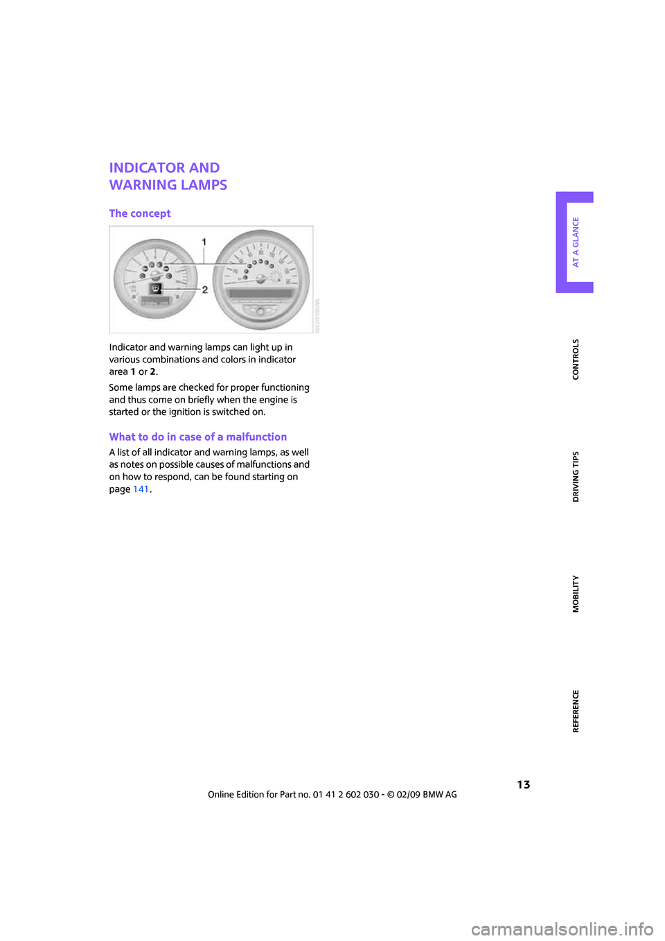
Indicator and warning lamps can light up in
various combinations and colors in indicator
area 1 or2.
Some lamps are checked for proper functioning
and thus come on briefly when the engine is
started or the ignition is switched on.
What to do in case of a malfunction
A list of all indicator and warning lamps, as well
as notes on possible causes of malfunctions and
on how to respond, can be found starting on
page141.
Page 20 of 176

Opening and closing
18
Opening and closing
Keys/remote controls
Remote control
Each remote control contains a rechargeable
battery that is recharged when it is in the igni-
tion lock while the car is being driven. You
should therefore use each remote control at
least twice a year to maintain the charge status.
In vehicles equipped with convenient access
*,
the remote control contains a replaceable bat-
tery, page27.
If more than one remote control unit is used, the
settings called up and implemented depend on
which remote control is recognized when the
car is unlocked, refer to Personal Profile,
page18.
In addition, information about service require-
ments is stored in the remote control, refer to
Service data in the remote control, page120.
New remote controls
Your MINI Dealer can supply new remote con-
trols as additional units or as replacements in the
event of loss.
Integrated key
Press button1 to release the key.
The integrated key fits the following locks:
>Driver's door, page22.
>MINI Convertible: Glove compartment, refer
to page85.
>MINI Convertible: Locking the rear seat
backrest95.
Personal Profile
The concept
The functions of your MINI can be set individu-
ally. By means of Personal Profiles, most of these
settings are stored for the remote control cur-
rently in use. When you unlock the car, the
remote control is recognized and the settings
stored for it are called up and implemented.
This means that your settings will be activated
for you, even if in the meantime your car was
used by someone else with another remote con-
trol and the corresponding settings.
At most three remote controls can be set for
three different people. A prerequisite is that
each person uses a separate remote control.
Personal Profile settings
For more information on specific settings, refer
to the specified pages.
>Response of the central locking system
when the car is being unlocked19
Page 33 of 176
REFERENCEAT A GLANCE CONTROLS DRIVING TIPS MOBILITY
31
>Ensure the cargo does not push against the
luggage compartment roll-up cover from
below.
>Ensure the tailgate is closed.
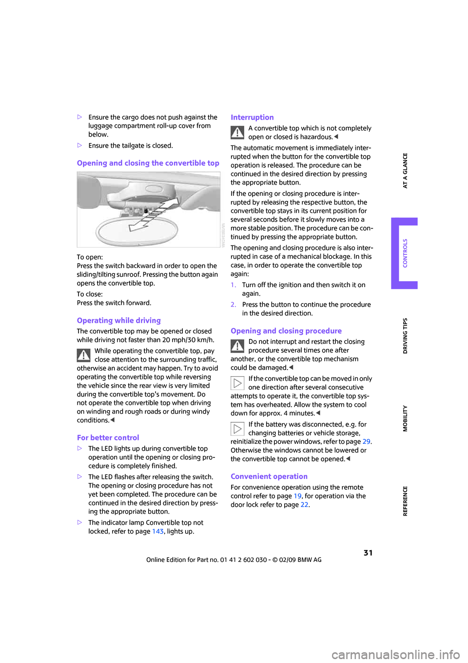
Opening and closing the convertible top
To open:
Press the switch backward in order to open the
sliding/tilting sunroof. Pressing the button again
opens the convertible top.
To close:
Press the switch forward.
Operating while driving
The convertible top may be opened or closed
while driving not faster than 20 mph/30 km/h.
While operating the convertible top, pay
close attention to the surrounding traffic,
otherwise an accident may happen. Try to avoid
operating the convertible top while reversing
the vehicle since the rear view is very limited
during the convertible top's movement. Do
not operate the convertible top when driving
on winding and rough roads or during windy
conditions.<
For better control
>The LED lights up during convertible top
operation until the opening or closing pro-
cedure is completely finished.
>The LED flashes after releasing the switch.
The opening or closing procedure has not
yet been completed. The procedure can be
continued in the desired direction by press-
ing the appropriate button.
>The indicator lamp Convertible top not
locked, refer to page143, lights up.
Interruption
A convertible top which is not completely
open or closed is hazardous.<
The automatic movement is immediately inter-
rupted when the button for the convertible top
operation is released. The procedure can be
continued in the desired direction by pressing
the appropriate button.
If the opening or closing procedure is inter-
rupted by releasing the respective button, the
convertible top stays in its current position for
several seconds before it slowly moves into a
more stable position. The procedure can be con-
tinued by pressing the appropriate button.
The opening and closing procedure is also inter-
rupted in case of a mechanical blockage. In this
case, in order to operate the convertible top
again:
1.Turn off the ignition and then switch it on
again.
2.Press the button to continue the procedure
in the desired direction.
Opening and closing procedure
Do not interrupt and restart the closing
procedure several times one after
another, or the convertible top mechanism
could be damaged.<
If the convertible top can be moved in only
one direction after several consecutive
attempts to operate it, the convertible top sys-
tem has overheated. Allow the system to cool
down for approx. 4 minutes.<
If the battery was disconnected, e.g. for
changing batteries or vehicle storage,
reinitialize the power windows, refer to page29.
Otherwise the windows cannot be lowered or
the convertible top cannot be opened.<
Convenient operation
For convenience operation using the remote
control refer to page19, for operation via the
door lock refer to page22.
Page 34 of 176
Opening and closing
32
Manual closing in the event of an
electrical malfunction
Only close the convertible top manually if
it is absolutely necessary. Never open it
manually. Improper handling of the convertible
top can result in damage. The closing procedure
must be completely finished. Otherwise, dam-
age or injury could result.<
Before closing
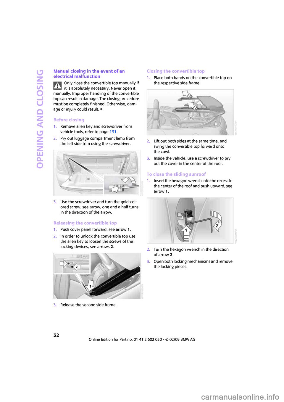
1.Remove allen key and screwdriver from
vehicle tools, refer to page131.
2.Pry out luggage compartment lamp from
the left side trim using the screwdriver.
3.Use the screwdriver and turn the gold-col-
ored screw, see arrow, one and a half turns
in the direction of the arrow.
Releasing the convertible top
1.Push cover panel forward, see arrow1.
2.In order to unlock the convertible top use
the allen key to loosen the screws of the
locking devices, see arrows 2.
3.Release the second side frame.
Closing the convertible top
1.Place both hands on the convertible top on
the respective side frame.
2.Lift out both sides at the same time, and
swing the convertible top forward onto
the cowl.
3.Inside the vehicle, use a screwdriver to pry
out the cover in the center of the roof.
To close the sliding sunroof
1.Insert the hexagon wrench into the recess in
the center of the roof and push upward, see
arrow1.
2.Turn the hexagon wrench in the direction
of arrow 2.
3.Open both locking mechanisms and remove
the locking pieces.
Page 35 of 176

REFERENCEAT A GLANCE CONTROLS DRIVING TIPS MOBILITY
33
4.Insert the pins into the respective recess in
the cowl, see arrow.
To lock the convertible top
Turn hexagon wrench in the opposite direction
of arrow 2 until the convertible top is securely
locked.
Please contact your MINI Dealer to have
the electrical malfunction repaired.<
Wind deflector*
With the convertible top open, the wind deflec-
tor keeps air movement in the passenger com-
partment to a minimum, thus providing you with
a more pleasant drive, even at higher speeds.
Do not let the wind deflector come into
contact with pointy objects as these may
damage the net. Do not place objects on the
installed wind deflector. When stowing the wind
deflector, ensure that it is not damaged by
objects.<
Before installing
1.Take the wind deflector out of the pouch.
2.Unfold the wind deflector, see arrows 1.3.Press the locking device together until it
engages, see arrow 2.
Installing and folding up
1.Push out retaining pin 2 on one side until it
engages.
2.Insert wind deflector with retaining pins into
the openings 1 and 2 on that side of the
vehicle.
3.On the opposite side of the vehicle, insert
the retaining pin 1 into the opening, pushing
against the spring load.
4.Push out retaining pin 2 on one side until it
engages.
5.Fold up the upper part of the wind deflector.
If a seat is in its rearmost position, do not
recline the backrest too far, otherwise the
wind deflector could be damaged.<
Page 37 of 176

REFERENCEAT A GLANCE CONTROLS DRIVING TIPS MOBILITY
35
Adjustments
Sitting safely
The ideal sitting position can make a vital contri-
bution to relaxed, fatigue-free driving. In con-
junction with the safety belts, the head restraints
and the airbags, the seated position has a major
influence on your safety in the event of an acci-
dent. To ensure that the safety systems operate
with optimal efficiency, we strongly urge you to
observe the instructions contained in the follow-
ing section.
For additional information on transporting chil-
dren safely, refer to page41.
Airbags
Always maintain an adequate distance
between yourself and the airbags. Always
grip the steering wheel on the rim, with your
hands in the 3 o'clock and 9 o'clock positions, to
minimize the risk of injury to the hands or arms
in the event of the airbag being triggered off.
No one and nothing is to come between the air-
bags and the seat occupant.
Do not use the cover of the front airbag on the
front passenger side as a storage area. Ensure
that the front passenger is correctly seated, e.g.
that no feet or legs are propped against the
dashboard. Otherwise, leg injury could result if
the front airbag suddenly deployed.
Make sure that passengers keep their heads
away from the side airbag and do not lean
against the cover of the head airbag of the MINI;
otherwise, serious injuries can result when the
airbag deploys.<
Even if you follow all the instructions, injuries
resulting from contact with airbags cannot be
fully excluded, depending on the circumstances.
The ignition and inflation noise may provoke a
mild hearing loss in extremely sensitive individ-
uals. This effect is usually only temporary.
For airbag locations and additional information
on airbags, refer to page71.
Head restraint
A correctly adjusted head restraint reduces the
risk of neck injury in the event of an accident.
Adjust the head restraint in such a way
that its center is at approx. ear level. Oth-
erwise, there is an increased risk of injury in the
event of an accident.<
Head restraints, refer to page37.
Safety belt
Before every drive, make sure that all occupants
wear their safety belts. Airbags complement the
safety belt as an additional safety device, but
they do not represent a substitute.
Never allow more than one person to
wear a single safety belt. Never allow
infants or small children to ride in a pas-
senger's lap.
Make sure that the belt in the lap area sits low
across the hips and does not press against the
abdomen. The safety belt must not rest against
the throat, run across sharp edges, pass over
hard or fragile objects or be pinched. Fasten the
safety belt so that it is pulled taut across the lap
and shoulder, fitting the body snugly without
any twists. Otherwise the belt could slide over
the hips in the event of a frontal collision and
injure the abdomen. Avoid wearing bulky cloth-
ing and regularly pull the belt in the upper-body
area taut, otherwise its restraining effect could
be impaired.<
Safety belts, refer to page38.
Seats
Note before adjusting
Never attempt to adjust your seat while
the vehicle is moving. The seat could
respond with unexpected movement, and the
ensuing loss of vehicle control could lead to an
accident.
On the front passenger seat as well, do not
Page 55 of 176
REFERENCEAT A GLANCE CONTROLS DRIVING TIPS MOBILITY
53
Everything under control
Odometer, outside
temperature display,
clock
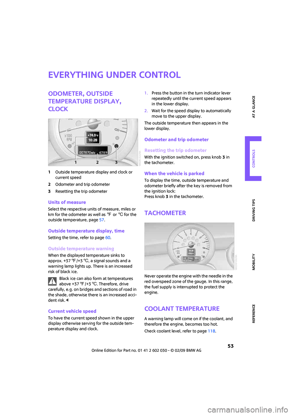
1Outside temperature display and clock or
current speed
2Odometer and trip odometer
3Resetting the trip odometer
Units of measure
Select the respective units of measure, miles or
km for the odometer as well as 7 or 6 for the
outside temperature, page57.
Outside temperature display, time
Setting the time, refer to page60.
Outside temperature warning
When the displayed temperature sinks to
approx. +377/+36, a signal sounds and a
warning lamp lights up. There is an increased
risk of black ice.
Black ice can also form at temperatures
above +377/+36. Therefore, drive
carefully, e.g. on bridges and sections of road in
the shade, otherwise there is an increased acci-
dent risk.<
Current vehicle speed
To have the current speed shown in the upper
display otherwise serving for the outside tem-
perature display and clock.1.Press the button in the turn indicator lever
repeatedly until the current speed appears
in the lower display.
2.Wait for the speed display to automatically
move to the upper display.
The outside temperature then appears in the
lower display.
Odometer and trip odometer
Resetting the trip odometer
With the ignition switched on, press knob 3 in
the tachometer.
When the vehicle is parked
To display the time, outside temperature and
odometer briefly after the key is removed from
the ignition lock:
Press knob 3 in the tachometer.
Tachometer
Never operate the engine with the needle in the
red overspeed zone of the gauge. In this range,
the fuel supply is interrupted to protect the
engine.
Coolant temperature
A warning lamp will come on if the coolant, and
therefore the engine, becomes too hot.
Check coolant level, refer to page118.
Page 56 of 176

Everything under control
54
Fuel gauge
Fuel tank capacity
Approx. 13.2 US gallons/50 liters.
You can find information on refueling on
page102.
If the tilt of the vehicle varies for a longer period,
when you are driving in mountainous areas, for
example, the indicator may fluctuate slightly.
Reserve
Once the fuel level has fallen to the reserve zone
of approx. 2.1 gallons/8 liters, the remaining
indicator lamps change from orange to red,
arrow. The tachometer
displays the remaining
cruising range. An indicator lamp comes on
when the remaining range is less than approx.
30 miles/50 km.
If the range displayed is less than
30 miles/50 km, be sure to refuel; other-
wise engine functions are not guaranteed and
damage could occur.<
Computer*
Displays in tachometer
Press the button in the turn indicator lever
repeatedly to call up various items of infor-
mation.
The following items of information are displayed
in the order listed:
>Cruising range
>Average fuel consumption
>Current fuel consumption
>Average speed
>Current vehicle speed
>MINI Convertible: Always Open Timer
To set the corresponding units of measure, refer
to Formats and units of measure on page57.
Cruising range
Displays the estimated cruising range available
with the remaining fuel. The range is calculated
on the basis of the way the car has been driven
over the last 18 miles/30 km and the amount of
fuel currently in the tank.
If the range displayed is less than
30 miles/50 km, be sure to refuel; other-
wise engine functions are not guaranteed and
damage could occur.<
Average fuel consumption
Calculated for the time the engine has been
running.
To reset average fuel consumption: press the
button in the turn indicator lever for approx.
2seconds.
Page 58 of 176

Everything under control
56
Settings and information
Operating principle
Certain settings and information are only avail-
able when the ignition is switched on, the vehi-
cle is at a standstill and the doors are closed.
1Button for:
>Selecting display
>Setting values
>Confirming selected display or set values
>Calling up computer information54
2Calling up Check Control60
3Displaying vehicle check61
4Initializing the Flat Tire Monitor66
Resetting the Tire Pressure Monitor68
5Setting formats and units of measure, reset-
ting to factory settings586Adjusting settings
>Confirmation signals when locking and
unlocking the vehicle20
>Response during unlocking
procedure19
>Automatic locking22
>Pathway lighting74
>Daytime running lamps75
>Triple turn signal activation48
7Setting the time60
8Setting the date60
9Exiting the menu
Page 61 of 176
REFERENCEAT A GLANCE CONTROLS DRIVING TIPS MOBILITY
59
The extent of service work required can be
read out from the remote control by your
MINI Dealer.<
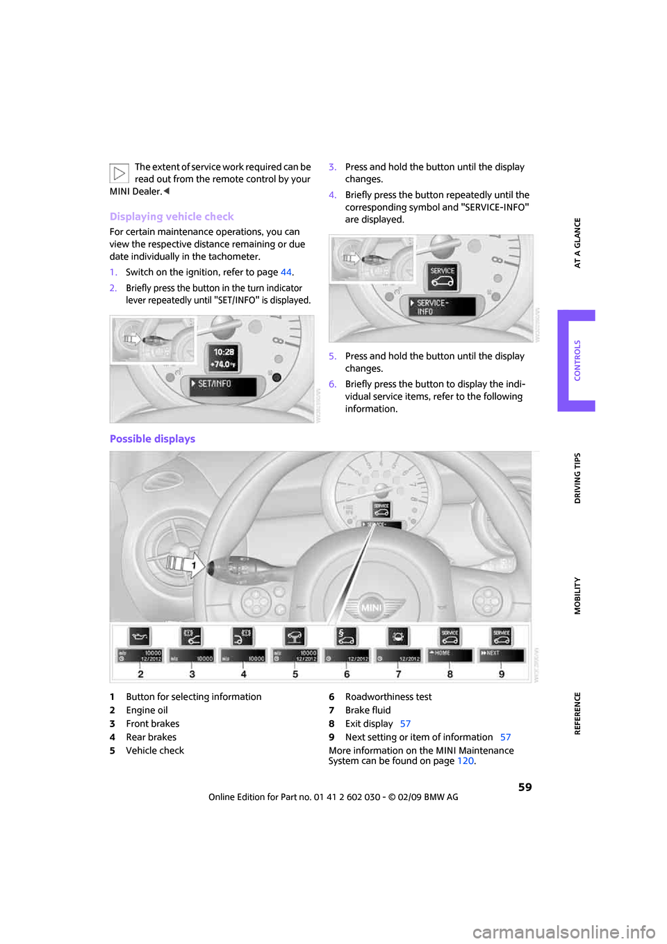
Displaying vehicle check
For certain maintenance operations, you can
view the respective distance remaining or due
date individually in the tachometer.
1.Switch on the ignition, refer to page44.
2.Briefly press the button in the turn indicator
lever repeatedly until "SET/INFO" is displayed.
3.Press and hold the button until the display
changes.
4.Briefly press the button repeatedly until the
corresponding symbol and "SERVICE-INFO"
are displayed.
5.Press and hold the button until the display
changes.
6.Briefly press the button to display the indi-
vidual service items, refer to the following
information.
Possible displays
1Button for selecting information
2Engine oil
3Front brakes
4Rear brakes
5Vehicle check6Roadworthiness test
7Brake fluid
8Exit display57
9Next setting or item of information57
More information on the MINI Maintenance
System can be found on page120.