key MINI COOPER 2003 Owner's Manual
[x] Cancel search | Manufacturer: MINI, Model Year: 2003, Model line: COOPER, Model: MINI COOPER 2003Pages: 148, PDF Size: 3.17 MB
Page 57 of 148

55
OVERVIEW REPAIRS OPERATIONCONTROLS DATA INDEX
WASHER/WIPER SYSTEMNormal wiper speedThe wiper speed is automatically set to
interval operation when the car is stopped.
Not on vehicles with rain sensor.
You can have this function activated/
deactivated by your MINI Dealer.
speed.
Not on vehicles with rain sensor.
You can have this function activated/
deactivated by your MINI Dealer.<
Cleaning windshield and headlamps*The system sprays washer fluid against the
windshield. The wipers are automatically
activated for a brief period.
When the vehicle lighting is on, the head-
lamps are also cleaned at appropriate inter-
vals.
Do not use the washers if there is any
danger that the fluid will freeze on
the windshield. If you do so, your vision
could be obscured. For this reason, use an
antifreeze agent, see page 94.
Do not use the washers when the reservoir
is empty, since this could cause damage to
the washing pump.
position 2.
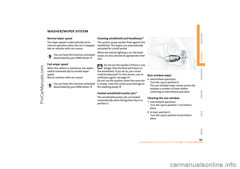
Rear window wiper6Intermittent operation:
Turn the cap to position 6.
The rear window wiper moves across the
window a number of times before
switching to intermittent operationCleaning the rear window7Intermittent operation:
Turn the cap to position 7 and hold in
place
8In lever position 0:
Turn the cap to position 8 and hold in
place
ba.book Seite 55 Montag, 5. August 2002 8:09 20
ProCarManuals.com
Page 58 of 148

56
CRUISE CONTROL
*
Do not use cruise control on twisting
roads, when high traffic density pre-
vents driving at a constant speed, when the
road surface is slick, e.g. from snow, rain or
ice, nor when the road surface is loose,
e.g. from rocks or sand.<
To activate the system From ignition key position 1:
Press button 2.
The indicator lamp in the instrument clus-
ter lights up.
Cruise control is active.
To maintain and store speed or to
accelerateThe vehicle maintains and stores any
desired speed when driving above approx.
20 mph / 30 km/h and, for manual trans-
missions, when the selector lever is in 3rd
gear or higher.
Press button 3.
The system maintains and stores the cur-
rent vehicle speed. Every time you tap the
button, the speed increases by approx.
1 mph / 2 km/h.
Press and hold button 3.
The vehicle accelerates without pressure on
the accelerator pedal. When you release
the button, the system maintains and
stores the current speed.
If, on a downhill gradient, the engine
braking effect is not sufficient, the
controlled speed may be exceeded. Speed
can drop on uphill grades if the engine out-
put is insufficient.<
To deceleratePress button 4.
If you are already driving with active cruise
control, the speed is decreased by approx.
1 mph / 2 km/h every time you briefly tap
the button.
Press and hold button 4.
With the cruise control active, the system
automatically reduces the throttle opening
to slow the vehicle. When you release the
button, the system maintains and stores
the current speed.
ba.book Seite 56 Montag, 5. August 2002 8:09 20
ProCarManuals.com
Page 59 of 148

57
OVERVIEW REPAIRS OPERATIONCONTROLS DATA INDEX
CRUISE CONTROL
*
To cancel the cruise control
When the system is activated, press
button 2.
The indicator lamp stays lit.
You can use the cruise control again as
required.
In addition, cruise control is canceled auto-
matically
>when the brakes are applied
>when you apply pressure to the clutch
pedal, or when you move the CVT selec-
tor lever from D to P, N or R
>or if the cruise speed is either exceeded
or not met for an extended length of
time, for example if you press the accel-
erator pedal and exceed the stored
speed.
To continue cruise controlPress button 1.
The vehicle accelerates to and maintains
the last speed stored. If you turn the igni-
tion key to position 0, the stored speed is
deleted and the system is deactivated.To deactivate the systemPress button 2 repeatedly until the indica-
tor lamp goes out.
The stored speed is cleared.
ba.book Seite 57 Montag, 5. August 2002 8:09 20
ProCarManuals.com
Page 60 of 148

58
ODOMETER TACHOMETER FUEL GAUGE 1Trip odometerTo set to zero:
With ignition key in position 1, press the
button until the trip odometer is at zero.2Odometer You can activate the displays shown in the
illustration, with the ignition key in
position 0, by pressing the button in the
instrument cluster.
Do not operate the engine with the needle
in the red overspeed zone of the gauge.
To protect the engine, the power is reduced
when you approach a certain engine speed
in this sector.
In the speedometerIf the indicator light 1 begins to be lit con-
tinuously, there are approx. 2.1 gallons /
8 liters of fuel in the tank.
Fuel tank capacity:
approx. 13.2 gallons / 50 liters.
When you switch on the ignition, the indi-
cator lamp lights up briefly to confirm that
the system is operational.
If the angle of the vehicle varies, for exam-
ple when you are driving in mountainous
areas, the needle may fluctuate slightly.
Refill the gas tank early. If you drive
to the last drop of fuel, engine func-
tions are not guaranteed and damage can
occur.<
ba.book Seite 58 Montag, 5. August 2002 8:09 20
ProCarManuals.com
Page 62 of 148

60
SERVICE INTERVAL DISPLAY CLOCK COMPUTER
*
Remaining distance for service
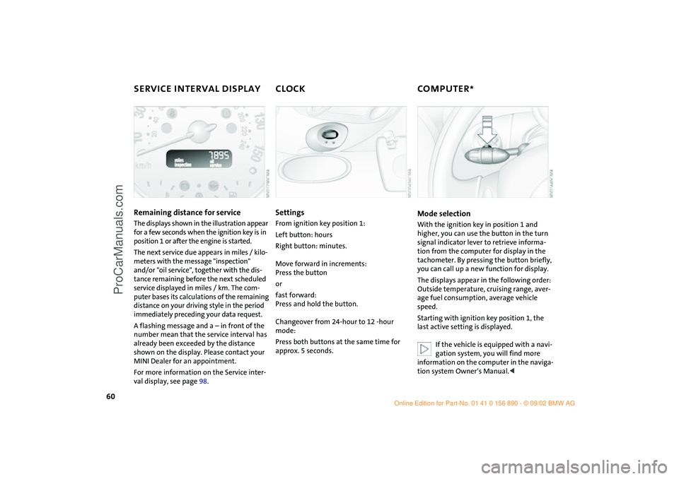
The displays shown in the illustration appear
for a few seconds when the ignition key is in
position 1 or after the engine is started.
The next service due appears in miles / kilo-
meters with the message "inspection"
and/or "oil service", together with the dis-
tance remaining before the next scheduled
service displayed in miles / km. The com-
puter bases its calculations of the remaining
distance on your driving style in the period
immediately preceding your data request.
A flashing message and a – in front of the
number mean that the service interval has
already been exceeded by the distance
shown on the display. Please contact your
MINI Dealer for an appointment.
For more information on the Service inter-
val display, see page 98.
SettingsFrom ignition key position 1:
Left button: hours
Right button: minutes.
Move forward in increments:
Press the button
or
fast forward:
Press and hold the button.
Changeover from 24-hour to 12 -hour
mode:
Press both buttons at the same time for
approx. 5 seconds.
Mode selectionWith the ignition key in position 1 and
higher, you can use the button in the turn
signal indicator lever to retrieve informa-
tion from the computer for display in the
tachometer. By pressing the button briefly,
you can call up a new function for display.
The displays appear in the following order:
Outside temperature, cruising range, aver-
age fuel consumption, average vehicle
speed.
Starting with ignition key position 1, the
last active setting is displayed.
If the vehicle is equipped with a navi-
gation system, you will find more
information on the computer in the naviga-
tion system Owner‘s Manual.<
ba.book Seite 60 Montag, 5. August 2002 8:09 20
ProCarManuals.com
Page 67 of 148

65
OVERVIEW REPAIRS OPERATIONCONTROLS DATA INDEX
FLAT TIRE MONITORInitializing the systemOnly initialize the system if the inflation
pressure has been corrected or changed,
e.g. after a tire change.
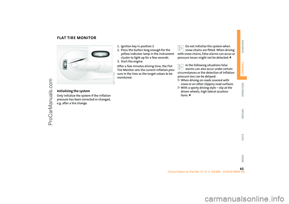
1. Ignition key in position 2
2. Press the button long enough for the
yellow indicator lamp in the instrument
cluster to light up for a few seconds
3. Start the engine.
After a few minutes driving time, the Flat
Tire Monitor sets the current inflation pres-
sure in the tires as the target values to be
monitored.Do not initialize the system when
snow chains are fitted. When driving
with snow chains, false alarms can occur or
pressure losses might not be detected.<
In the following situations false
alarms can also occur under certain
circumstances or the detection of inflation
pressure loss can be delayed:
>When driving on roads covered with
snow or on other slippery road surfaces
>With a sporty driving style – slip at the
driven wheels, high lateral accelera-
tions.<
ba.book Seite 65 Montag, 5. August 2002 8:09 20
ProCarManuals.com
Page 68 of 148

66
PARK DISTANCE CONTROL (PDC)*The conceptThe PDC assists you when you back into a
parking space. A signal tone tells you the
current distance to an object behind your
vehicle. To do this, four ultrasonic sensors
in the rear bumper measure the distance to
the nearest object.
The sensors on each side have a range of
approx. 2 ft / 60 cm, the middle sensors
one of approx. 5 ft / 1.5 m.
The system starts to operate automatically
about one second after you select reverse
with the ignition key in position 2.
Wait for this one second before you
drive backwards.<
PDC is deactivated when you shift away
from Reverse.
You can have a signal tone set by your
MINI Dealer as a confirmation that
PDC has been activated.<
Acoustical signalsThe distance to an object is indicated by a
tone sounding at intervals. As the distance
between vehicle and object decreases, the
intervals between the tones become
shorter. A continuous tone indicates the
presence of an object less than 8 in / 20 cm
away.
The warning signal is canceled after
approx. three seconds if the distance to the
object remains constant during this time,
for instance if you are moving parallel to a
wall.
System malfunctions will be indicated by a
continuous high-pitched tone when the
system is activated the first time. Please
have your MINI Dealer resolve the problem.Volume controlThe volume of the Park Distance Control
signal can be adjusted from level 1 – soft –
to level 6 – loud.
The volume can be set by your MINI
Dealer.<
Even with PDC, final responsibility for
estimating the distance between the
vehicle and any objects always remains
with the driver.
Even when sensors are involved, there is a
blind spot in which objects cannot be de-
tected. Recognition of some objects can be
beyond the limits of physical ultrasonic
measurement, for example with towing
bars or hitches or with thin or wedge-
shaped objects. Moreover, low objects that
have already been detected – such as a curb
edge – can disappear out of the range of
the sensors before a continuous tone
sounds.
Loud sources of sound outside and inside
your vehicle can drown the PDC signal
tone.<
Keep the sensors clean and free of ice
or snow in order to ensure that they
will continue to operate effectively.
Do not apply high pressure spray to the
sensors for a prolonged period of time.
Always maintain a distance which is
greater than 4 in / 10 cm.<
ba.book Seite 66 Montag, 5. August 2002 8:09 20
ProCarManuals.com
Page 75 of 148

73
OVERVIEW REPAIRS OPERATIONCONTROLS DATA INDEX
GLOVE COMPARTMENT ASHTRAY/BEVERAGE HOLDER
LIGHTER/12 V POWER SUPPLY
To open:
Pull the handle.
The light goes on.
To close:
Fold the door up.
To prevent injury in the event of an
accident, close the glove compart-
ment immediately after use.<
AshtrayThe ashtray is located in one of the bever-
age holders in the center console.
In the rear, an ashtray can also be fitted in
the beverage holder at the end of the cen-
ter console.Beverage holdersThere are two beverage holders at the front
of the center console. Another is located at
the end of the center console.
From ignition key position 1:
Press the cigarette lighter in.
Remove as soon as the lighter jumps back
out.
Hold or touch the hot cigarette lighter
by the knob only. Holding or touching
it in other areas could result in burns.
flashlights, car vacuum cleaners, etc., up to
a rating of approx. 200 Watts at 12 Volts.
Avoid damaging the socket with plugs of
different shapes or sizes.
The 12 V power supply is also used for sup-
plying the compressor of the MINI Mobility
System.
ba.book Seite 73 Montag, 5. August 2002 8:09 20
ProCarManuals.com
Page 122 of 148

120
FLAT TIRE – MINI MOBILITY SYSTEM
*
Reinflating the tire
1. Screw hose 1 with manometer onto the
tire valve
2. Connect plug 3 to the cigarette lighter
socket in the vehicle interior, see
page 73
3. Ignition key in position 1:
Turn on compressor 2
4. Pump up the tires to at least 26.1 psi /
180 kPa, but not to more than 36.2 psi /
250 kPa.
To check the current air pressure, shut
off the device for a short time
Do not run the compressor for
longer than 6 minutes, otherwise
the device will overheat and possibly be
damaged.<
If an air pressure of 26.1 psi /
180 kPa cannot be reached, drive
back and forth about 35 ft / 10 m so that
the liquid sealant is distributed in the
tire. Afterwards repeat the procedure.
If an air pressure of 26.1 psi / 180 kPa is
still not reached, the tire is too badly
damaged. Please contact the nearest
MINI Dealer.<
5. Turn off compressor 2
6. Unscrew hose 1 from the tire valve
7. Store the MINI Mobility System back in
the vehicle.
Distributing liquid sealantImmediately drive for 10 minutes, so that
the liquid sealant is uniformly distributed.
Do not exceed a speed of 40 mph /
60 km/h).
If possible do not drive at a speed lower
than 10 mph / 20 km/h. Stop at a suitable
location.<
ba.book Seite 120 Montag, 5. August 2002 8:09 20
ProCarManuals.com
Page 123 of 148

121
OVERVIEW REPAIRSOPERATION CONTROLS DATA INDEX
FLAT TIRE – MINI MOBILITY SYSTEM
*
Checking tire inflation pressure
1. After driving for 10 minutes:
Screw hose with manometer back onto
the tire valve
2. Check tire pressure
The tire inflation pressure must be
at least 18.8 psi / 130 kPa.
If it is not, do not continue driving.<
If 18.8 psi / 130 kPa are displayed:
3. Ignition key position 1:
Turn on compressor 2. Correct tire infla-
tion pressure to the prescribed value, see
tire inflation pressure table, page 86
4. Replace the tire as soon as possible.
The use of the MINI Mobility System
may be ineffective with tire damage
larger than approx.
3/16 in / 4 mm. Please
contact the nearest MINI Dealer if the tire
cannot be made drivable with the MINI
Mobility System.<
Driving on
Do not exceed the permitted maxi-
mum speed of 50 mph / 80 km/h,
otherwise an accident could happen.<
Replace the defective tire as soon as
possible and have the new wheel/tire
assembly balanced.
Have the MINI Mobility System refilled.
Please contact your MINI Dealer. They pro-
vide advice if you wish to replace the tires
on your MINI or re-equip from summer to
winter tires or vice versa.<
Tire change setYour MINI is additionally equipped with a
tire change set. This is located in the MINI
COOPER in the cargo area under the floor
mat.
When changing a tire, always observe the
safety measures on page 112, and follow
the procedure described on page 114 ff.
In case of a flat tire the tire change
set is not necessary due to the avail-
ability of the MINI Mobility System.<
ba.book Seite 121 Montag, 5. August 2002 8:09 20
ProCarManuals.com