tow MINI COOPER 2004 User Guide
[x] Cancel search | Manufacturer: MINI, Model Year: 2004, Model line: COOPER, Model: MINI COOPER 2004Pages: 152, PDF Size: 1.53 MB
Page 80 of 152

78
ROOF-MOUNTED LUGGAGE RACK
*
Always position and secure the load
carefully. If you do not, it can endan-
ger the passengers during braking or eva-
sive maneuvers.
Do not exceed the permissible gross weight
and axle load, refer to page 134; otherwise
the vehicle's operating safety is no longer
assured and it will not be in compliance
with the certification regulations.
Do not stow heavy or hard objects in the
passenger compartment without first
securing them. Otherwise they would be
thrown around during braking and evasive
maneuvers and endanger the occupants.<
When loading a roof-mounted lug-
gage rack, ensure that there is suffi-
cient space for the movement of the glass
sunroof and that no objects protrude into
the swiveling area of the tailgate, as other-
wise damage can occur.<
Do not secure the roof-mounted lug-
gage rack to the trim panels/strips:
the lack of a secure hold could lead to dam-
age or accidents.<
Special roof-mounted luggage racks
for your MINI are available as acces-
sories from your MINI Dealer.<
ProCarManuals.com
Page 86 of 152

84
REFUELING
Always switch off the engine before
refueling. If you do not, fuel cannot
be filled into the tank and the SERVICE
ENGINE SOON lamp may come on.<
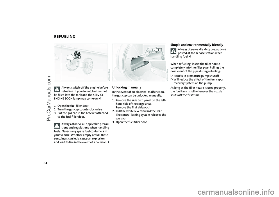
1. Open the fuel filler door
2. Turn the gas cap counterclockwise
3. Put the gas cap in the bracket attached
to the fuel filler door.
Always observe all applicable precau-
tions and regulations when handling
fuels. Never carry spare fuel containers in
your vehicle. Whether empty or full, these
containers can leak, cause an explosion,
and lead to fire in the event of a collision.<
Unlocking manually In the event of an electrical malfunction,
the gas cap can be unlocked manually.
1. Remove the side trim panel on the left-
hand side of the cargo area.
Remove the first aid pouch
2. Pull the white lever toward the rear.
The central locking system releases the
gas cap
3. Open the fuel filler door.
Simple and environmentally friendly
Always observe all safety precautions
posted at the service station when
handling fuel.<
When refueling, insert the filler nozzle
completely into the filler pipe. Pulling the
nozzle out of the pipe during refueling:
>Results in premature pump shutoff
>Will reduce the effect of the fuel vapor
recovery system on the pump.
As long as the filler nozzle is used properly,
the fuel tank is full whenever the nozzle
shuts off the first time.
ProCarManuals.com
Page 93 of 152

91
OVERVIEW REPAIRSOPERATIONCONTROLS DATA INDEX
TIRE CONDITION Tire tread Inspect your tires frequently for tread wear,
signs of damage and for foreign objects
lodged in the tread. Check the tread depth.
The tread depth should not fall below
1/8 in / 3 mm.
Below 1/8 in / 3 mm tread pattern depth,
there is an increased risk of hydroplaning,
even at relatively moderate speeds and
with only small amounts of water on the
road.
Below a tread depth of 1/6 in / 4 mm, win-
ter tires display a perceptible decrease in
their ability to cope with winter driving
conditions, and should be replaced in the
interest of safety.Wear indicators in the tread-groove base,
arrow, are spread around the circumfer-
ence of the tire and are marked on the side
wall of the tire with TWI, Tread Wear Indi-
cator. The indicators in the tread indicate at
1/16 in / 1.6 mm tread depth that the
legally permitted wear limit has been
reached.
Tire damage
Unusual vibrations while driving can
indicate tire damage or other dam-
age to the vehicle. This may be caused, for
example, by driving over a curb. This is also
true for abnormalities in the vehicle's han-
dling characteristics, such as a pronounced
tendency to pull to the left or right. Should
this occur, respond by immediately reduc-
ing your speed. Proceed carefully to the
nearest MINI Dealer or professional tire
center, or have the vehicle towed there to
have its wheels and/or tires inspected or
controlled. Tire damage – up to and includ-
ing blowouts – can endanger the lives of
both the vehicle occupants and other road
users.<
ProCarManuals.com
Page 100 of 152

98
WASHER FLUID ENGINE OILHeadlamp* and windshield washer
system The capacity of the headlamp washer sys-
tem is approx. 2.6 quarts / 2.5 liters, that of
the windshield washer system approx.
2.1 quarts / 2.0 liters.
Fill with water and, if required, with anti-
freeze, according to manufacturer's recom-
mendations.
We recommend that you mix the
washer fluid before adding it to the
reservoir.<
Antifreeze agent for the washer sys-
tems is flammable. Always keep it well
away from sparks and open flames, and store
it in tightly closed containers well out of the
reach of children. Always observe the instruc-
tions for use provided on the container.<
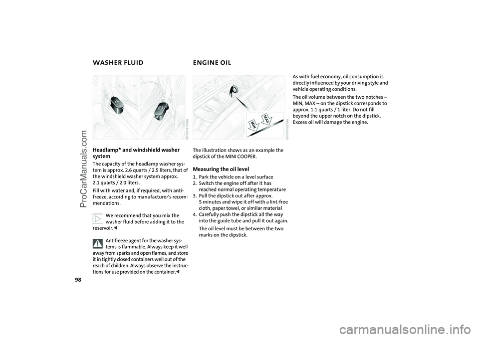
The illustration shows as an example the
dipstick of the MINI COOPER.Measuring the oil level1. Park the vehicle on a level surface
2. Switch the engine off after it has
reached normal operating temperature
3. Pull the dipstick out after approx.
5 minutes and wipe it off with a lint-free
cloth, paper towel, or similar material
4. Carefully push the dipstick all the way
into the guide tube and pull it out again.
The oil level must be between the two
marks on the dipstick.
As with fuel economy, oil consumption is
directly influenced by your driving style and
vehicle operating conditions.
The oil volume between the two notches –
MIN, MAX – on the dipstick corresponds to
approx. 1.1 quarts / 1 liter. Do not fill
beyond the upper notch on the dipstick.
Excess oil will damage the engine.
ProCarManuals.com
Page 112 of 152

110
ONBOARD TOOL KIT WINDSHIELD WIPER BLADES The picture shows as an example the tire
change set with onboard tools for vehicles
with the space-saver spare tire.
Depending on the level of equipment
options, your MINI is fitted with a special
onboard tool kit stored at the locations
described below:
Storage locationMINI Mobility System with tire change set
and onboard tools:
>In the cargo area under the floor mat.
Tire change set and onboard tools for Run
Flat tires:
>Tire change set:
In the cargo area in a separate pouch,
refer to page 123
>Onboard tool kit:
on the left-hand side of the cargo area
behind the side trim panel.
Tire change set with space-saver spare tire:
>In the cargo area under the floor mat.
Windshield wiper1. Rotate the wiper arm completely out
from the windshield
2. Set the wiper blade at an angle
3. Press the securing spring, arrow
4. Unhook the wiper blade towards the
windshield
5. Pull the wiper blade past the wiper arm
toward the top
6. Insert the new wiper blade
7. Press into position until you hear it
engage.
ProCarManuals.com
Page 115 of 152

113
OVERVIEW REPAIRSOPERATION CONTROLS DATA INDEX
LAMPS AND BULBSSide turn signal indicators 5 Watt bulb
1. Press lamp toward vehicle tailgate and
remove
2. Remove and replace the bulb.Side marker lamps3 Watt bulb
Side marker lamps in the wheelhouse pan-
eling of the bumper.
Please contact a MINI Dealer in case of a
malfunction.
Fog lamps*H11 bulb, 55 Watts
Please contact a MINI Dealer in case of a
malfunction.
Tail lampsRear lamp 3: bulb 21/5 Watts
Other bulbs: 21 Watts
1Rear fog lamp
*
red
2Turn signal indicator yellow
3Rear lamp red
4Rear lamp/Brake lamp red
ProCarManuals.com
Page 119 of 152

117
OVERVIEW REPAIRSOPERATION CONTROLS DATA INDEX
CHANGING TIRES: MINI WITH SPACE-SAVER SPARE TIRE
*
Additional safety measures in the
event of a wheel change:
Change the wheel only on a level, firm sur-
face which is not slippery.
The vehicle or the jack could slip sideways
on soft or slippery support surfaces, such as
snow, ice, flagstones, etc..
Do not use a wooden block or similar object
as a support base for the jack, as this would
prevent it from extending to its full support
height and reduce its load-carrying capac-
ity.
Do not lie under the vehicle or start the
engine when the vehicle is supported by
the jack – risk of fatal injury.<
To change a space-saver tire, proceed as
follows:
>Remove space-saver spare tire, refer to
the section after the next one
>Prepare for tire change, refer to page 119
>Jack up the vehicle, refer to page 119
>Fit the space-saver spare tire, refer to
page 120
>Tighten the lug bolts, refer to page 120
>Drive with space-saver spare tire, refer to
page 120.
Tire change set On vehicles with a space-saver spare tire,
the tire change set is stored in the cargo
area under the floor mat.
1Chock, folding
2Hubcap remover
3Wheel stud wrench
4Jack
5Lug wrench
6Towing eyelet
7Lifting handle
The onboard tool kit includes a pouch with
a plastic bag in which you can place the
damaged wheel.
Removing the space-saver spare tireThe screw connection of the space-saver
spare tire is in the cargo area under the
floor mat, on the base of the storage com-
partment for the tire change set.
1. Loosen the screw connection using the
wheel lug bolt wrench
2. Take out the cover panel
ProCarManuals.com
Page 120 of 152

118
CHANGING TIRES: MINI WITH SPACE-SAVER SPARE TIRE
*
3. Screw the lifting handle from the
onboard tool kit onto the thread
4. Raise the lifting handle slightly
5. Squeeze the securing springs
6. The space-saver spare tire is released
and must be held by the lifting handle
7. Lower the space-saver spare tire with
the lifting handle
8. Unscrew the lifting handle again
9. Pull out the space-saver spare tire
towards the rear underneath the vehi-
cle
10. Position the space-saver spare tire with
the valve facing upwards
11. Unscrew the valve extension from the
valve of the space-saver spare tire
12. Unscrew the dust cap from the exten-
sion and attach to the valve on the
spare tire.
Due to its different dimensions, the
damaged wheel cannot be placed in
the recess for the space-saver spare tire.<
ProCarManuals.com
Page 123 of 152

121
OVERVIEW REPAIRSOPERATION CONTROLS DATA INDEX
MINI MOBILITY SYSTEM
*
MINI Mobility System
To repair a flat tire you will find a MINI
Mobility System in your MINI. With the
help of this system you can apply a liquid
sealant on the inside of the tire, which seals
the damaged area and enables you to con-
tinue to drive.Preparing for tire repair
Before using the MINI Mobility Sys-
tem read the warning and danger
precautions on the equipment.<
If possible, leave objects in which have
been forced into the tire.
Take off the tag regarding speed limits and
stick it onto the steering wheel.
Using the MINI Mobility SystemIn order to repair a flat tire with the MINI
Mobility System, proceed as follows:
>Pump in liquid sealant, refer to page 122
>Reinflate the tire, refer to page 122
>Distribute liquid sealant, refer to
page 123
>Check tire inflation pressure, refer to
page 123
>Drive on, refer to page 123.
MINI Mobility System with onboard
tools The MINI Mobility System with tire change
set and onboard tools is located in the
cargo area under the floor mat:
1Jack
2Chock, folding
3Wheel stud wrench
4Hubcap remover
5Wrench, screwdriver/Phillips screw-
driver, towing eyelet
6Compressor, hose with manometer and
plug for cigarette lighter socket
7Package with filling hose, valve
remover and valve core
8Filling canister
9Hex wrench/screwdriver
10 Adapter for wheel lug lock
ProCarManuals.com
Page 130 of 152

128
TOWING For towing, use either a tow bar or nylon
ropes or straps that prevent sudden jerking
movements.Towing eyelet The screw-in towing eyelet is stored in the
onboard tool kit; be sure that it remains in
the vehicle at all times. It can be attached
at the front or rear of the vehicle.Access to tow socketsUse a suitable object, e.g. credit card,
screwdriver, to press out the covers from
the recess.
Use only the towing eyelet supplied
with the vehicle and screw it in firmly
until it stops. Use the towing eyelet for
towing on paved roads only. If you do not
follow these instructions, the towing eyelet
could detach itself from the vehicle or the
vehicle could be damaged. Never attach
tie-down hooks, chains, straps, or tow
hooks to tie rods, control arms, or any other
part of the vehicle suspension, as this could
damage the components and possibly lead
to accidents.<
Avoid staggered towing and make
sure that the towing rope is taut
before the vehicle that is towing drives
off.<
Tow bars If the towing eyelets of the two vehicles are
not directly opposite one another, please
note:
>Clearance and maneuvering capability
will be strictly limited in corners
>The inclination of the tow bar generates
lateral force, critical above all if the road
surface is slippery.
Do not tow a vehicle that is heavier
than the towing vehicle; otherwise it
will no longer be possible to control the
vehicle's response.<
ProCarManuals.com