MINI COOPER 2005 Manual PDF
Manufacturer: MINI, Model Year: 2005, Model line: COOPER, Model: MINI COOPER 2005Pages: 165, PDF Size: 4.64 MB
Page 71 of 165
69
OVERVIEW REPAIRS OPERATIONCONTROLS DATA INDEX
DYNAMIC STABILITY CONTROL (DSC)
*
The conceptThis system optimizes driving stability and
traction, especially when just starting off,
when accelerating or when cornering. It
also maintains driving stability even in crit
-
ical driving situations.DSC recognizes unstable vehicle conditions,
such as understeering or oversteering, and,
as far as is possible within the laws of phys
-
ics, helps keep the vehicle on a steady
course by reducing the rpms and by brake
applications to the individual wheels.The DSC is operational every time you start
the engine. It contains the following func
-
tions:>All Season traction Control (ASC)>Antilock Brake System (ABS)>Cornering Brake Control (CBC)>Electronic Brake Force Distribution (EBD).
The laws of physics cannot be repealed, even with DSC. An appro
-
priate driving style always remains the
responsibility of the driver. Avoid using the
additional safety margin provided by the
system as an excuse for taking unnecessary
risks.
Do not make any modifications to the DSC
system. Allow only authorized technicians
to perform service procedures on the
DSC.
switched on, refer to pages
17, 18
.
If the indicator lamp flashes:
DSC controls the drive and braking forces. The indicator lamp stays lit:
The system is defective or was turned off
using the button. Have the system checked
as soon as possible.
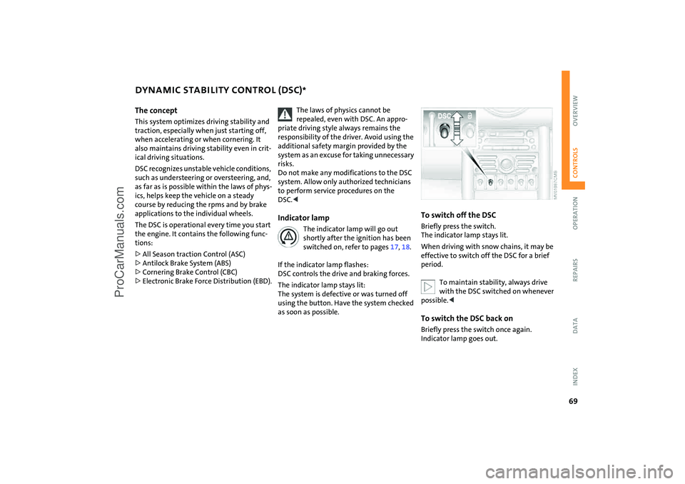
To switch off the DSCBriefly press the switch.
The indicator lamp stays lit.When driving with snow chains, it may be
effective to switch off the DSC for a brief
period.
To maintain stability, always drive with the DSC switched on whenever
possible.<
To switch the DSC back onBriefly press the switch once again.
Indicator lamp goes out.
ProCarManuals.com
Page 72 of 165

70
ANTILOCK BRAKE SYSTEM (ABS) The concept The ABS keeps the wheels from locking
while braking, thereby enhancing active
driving safety. ABS also includes Electronic Brake Force
Distribution (EBD).Safe brakingYour vehicle is equipped with ABS as a stan
-
dard feature. The best way to brake the
vehicle in critical situations requiring brak
-
ing is to apply maximum pressure to the
brake pedal: panic stop.
Since the vehicle remains maneuverable,
you can still go around any obstacles with
the smallest possible steering movements.The pulsation of the brake pedal, together
with the sound of hydraulic regulation,
indicates to you that ABS is actively taking
effect.
Cornering Brake Control (CBC)Cornering Brake Control (CBC) is an
enhancement of ABS that improves vehicle
stability especially when braking during
cornering.
When the vehicle is being braked, the rear
wheels are relieved from load, and this can
cause the vehicle to oversteer in curves.
CBC counteracts this by making use of uni
-
lateral braking pressure to generate a sta
-
bilizing counter torque while braking out
-
side of the ABS control range.Electronic Brake Force Distribution
(EBD)In order to achieve a short braking distance
when the vehicle is fully loaded, your vehi
-
cle is equipped with relatively large brakes
on the rear axle. EBV continuously moni
-
tors the speeds of the rear wheels in rela
-
tion to the front wheels in order to prevent
overbraking of the rear wheels even when
the vehicle has a light load. If the rear
wheels tend to lock, the EBV controls their
slip, ensuring operating stability.
ProCarManuals.com
Page 73 of 165
71
OVERVIEW REPAIRS OPERATIONCONTROLS DATA INDEX
FLAT TIRE MONITOR The conceptAs you drive, the Flat Tire Monitor keeps
track of the tire inflation pressure in all four
tires. The system alerts you when there is a
substantial pressure loss in one of the tires
relative to another.The tire inflation pressures are monitored
based on the speeds of the four wheels in
relation to one another. A flat tire is
detected as the result of differences in cer
-
tain speed ratios, and a warning is gener
-
ated.System requirementsSo that the system can 'familiarize' itself
with the correct inflation pressure, please
do the following:1. Check the tire inflation pressure in all
tires2. Compare them with the inflation pres
-
sure table, refer to page
98, and adjust
the pressures if necessary
3. Initialize the system.
System limitations
The Flat Tire Monitor cannot alert you to severe and sudden tire damage
caused by external factors, nor does it
detect the gradual and minor loss of pres
-
sure in all four tires.
-
sure loss or to the system not functioning:>Driving on snow-covered or slippery
roads>Performance-oriented driving: slip at the
drive wheels, high rates of lateral accel
-
eration>When driving with snow chains, false
warnings and undetected pressure loss
may occur>When driving with a space-saver spare
tire, the Flat Tire Monitor cannot func
-
tion.
Initializing the system
The system must be reinitialized immediately after changing a tire
and wheel, or after correcting the pressure
in any tire. This requires a bit of driving.<
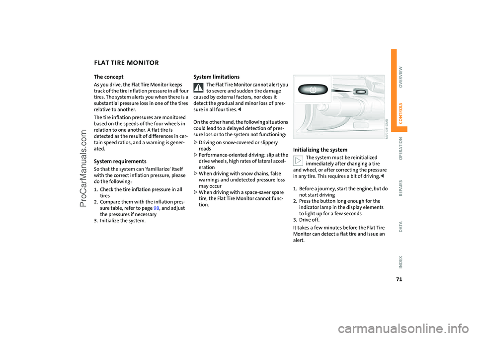
1. Before a journey, start the engine, but do
not start driving2. Press the button long enough for the
indicator lamp in the display elements
to light up for a few seconds3. Drive off.It takes a few minutes before the Flat Tire
Monitor can detect a flat tire and issue an
alert.
ProCarManuals.com
Page 74 of 165
72
FLAT TIRE MONITOR
AIRBAGS
Do not initialize the system if you are driving with snow chains or a space-
saver spare tire.<
Flat tire
The warning lamp lights up in yel
-
low. An acoustic signal also sounds.
There is a flat tire or a siginificant
loss of pressure in a tire.
1. Reduce speed and stop the vehicle with
caution. Avoid hard brake applications
and steering maneuvers2. Determine which tire is damaged
If this cannot be determined, con
-
tact your MINI Dealer.<
3. Repair the flat tire, refer to page
125
.
With Run Flat tires:1. Reduce vehicle speed carefully to under
50
mph
/ 80 km/h. Avoid hard brake
applications and steering maneuvers. Do
not exceed a speed of 50
mph
/ 80
km/h
2. Check the tire inflation pressure in all
four tires at the earliest opportunity.
If the tire inflation pressure is cor
-
rect in all four tires, it is possible
that the Flat Tire Monitor was not initial
-
ized. In this case, initialize the system.<
3. To continue driving, follow the instruc
-
tions on driving with damaged tires on
page
101
.
Malfunction
The warning lamp lights up in yel
-
low. There is a malfunction in the
Flat Tire Monitor or the system has
failed. Have the system checked as soon as
possible.
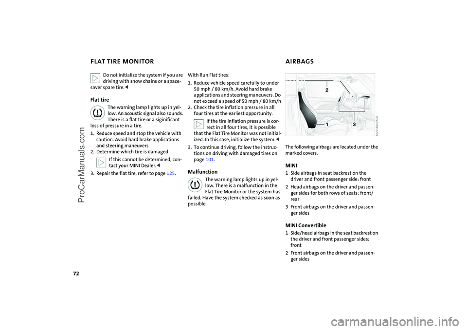
The following airbags are located under the marked covers.MINI 1 Side airbags in seat backrest on the
driver and front passenger side: front2 Head airbags on the driver and passen
-
ger sides for both rows of seats: front/
rear3 Front airbags on the driver and passen
-
ger sidesMINI Convertible1 Side/head airbags in the seat backrest on
the driver and front passenger sides:
front2 Front airbags on the driver and passen
-
ger sides
ProCarManuals.com
Page 75 of 165
73
OVERVIEW REPAIRS OPERATIONCONTROLS DATA INDEX
AIRBAGSProtective effectThe front airbags supplement the safety
belts by providing additional protection for
the driver and front passenger in the event
of a frontal collision in which the protec
-
tion afforded by the belts alone may no
longer be sufficient. When needed, the
head and side airbags help to furnish pro
-
tection in the event of side impact. Each of
the side airbags is designed to help support
the seat occupant's upper body. The corre
-
sponding side/head airbag in the MINI Con
-
vertible or the head airbag in the MINI sup
-
ports the head.The airbags are designed to not be trig
-
gered in certain types of collisions, e.g. in
minor accidents, certain kinds of vehicle
rollover and rear impact.For information on the ideal seating posi
-
tion, refer to page
41.
Do not apply adhesive materials to the cover panels of the airbags, cover
them or modify them in any other way. Do
not fit covers, cushions or other items to
the front seats that have not been specially
approved for seats with side airbags. Do
not hang clothing, e.
g. jackets, over the
backrests.
Do not attempt to remove the airbag
restraint system from the vehicle. Do not
touch the individual components directly
after the system has been triggered, as oth
-
erwise there is a danger of burns. In the
event of malfunctions, deactivation or
deployment of the airbag restraint system,
have the system checked, repaired or disas
-
sembled only by a MINI Dealer or a work
-
shop with specially trained personnel work
-
ing in accordance with the specifications of
the MINI manufacturer and having the nec
-
essary permits for handling explosive
devices. Unprofessional attempts to service
the system could lead to failure in an emer
-
gency or undesired airbag activation, either
of which could result in personal injury.
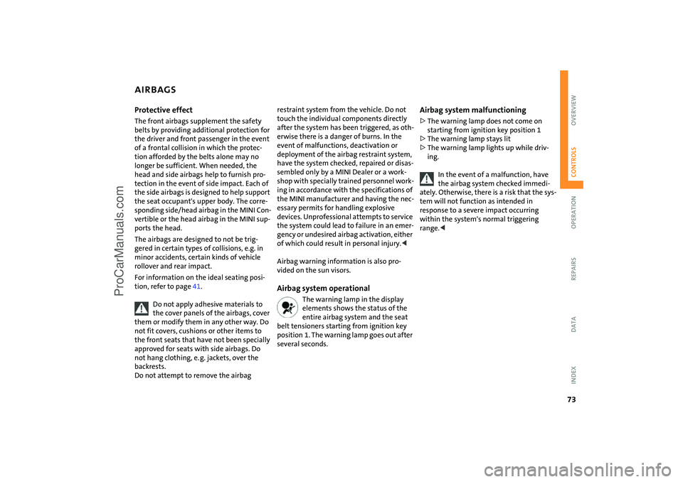
vided on the sun visors.Airbag system operational
The warning lamp in the display elements shows the status of the
entire airbag system and the seat
belt tensioners starting from ignition key
position 1. The warning lamp goes out after
several seconds.
Airbag system malfunctioning >The warning lamp does not come on
starting from ignition key position
1
>The warning lamp stays lit>The warning lamp lights up while driv
-
ing.
In the event of a malfunction, have the airbag system checked immedi
-
ately. Otherwise, there is a risk that the sys
-
tem will not function as intended in
response to a severe impact occurring
within the system's normal triggering
range.<
ProCarManuals.com
Page 76 of 165

74
PARK DISTANCE CONTROL (PDC)
*
The conceptThe PDC assists you when you back into a
parking space. A signal tone tells you the
current distance to an object behind your
vehicle. To do this, four ultrasonic sensors
in the rear bumper measure the distance to
the nearest object.
The sensors on each side have a range of
approx. 2
ft / 60
cm, the middle sensors
one of approx. 5 ft / 1.5
m.
PDC is a parking aid that can identify objects if they are approached slowly,
as is generally the case when parking.
Avoid driving towards objects rapidly; due
to underlying physical principles, the sys
-
tem may otherwise alert you too late for
you to take evasive steps.
-
tem starts to operate automatically about
one second after you select reverse gear or
place the selector lever in position R.
Wait for this one second before you drive backwards.<
The system is deactivated when you shift
away from Reverse.
You can have a signal tone set as a confirmation that PDC has been acti
-
vated.
between vehicle and object decreases, the
intervals between the tones become
shorter. A continuous tone indicates the
presence of an object less than 8
in / 20
cm
away.
The warning signal is canceled after
approx. three seconds if the distance to the
object remains constant during this time,
for instance if you are moving parallel to a
wall.MalfunctionA continuous high-pitched tone will sound
during initial activation. The system is mal
-
functioning. Have the system checked.Volume controlThe volume of the Park Distance Control
signal can be adjusted from level
1, soft, to
level
6, loud.You can have this function set.<
System limitations
Even with PDC, final responsibility for estimating the distance between the
vehicle and any objects always remains
with the driver.
Even when sensors are involved, there is a
blind spot in which objects cannot be
detected. Recognition of some objects can
be beyond the limits of physical ultrasonic
measurement, for example with towing
bars or hitches or with thin or wedge-
shaped objects. Moreover, low objects that
have already been detected, such as a curb
edge, can disappear out of the range of the
sensors before a continuous tone sounds.
Loud sources of sound outside and inside
your vehicle can drown the PDC signal
tone.<
Keep the sensors clean and free of ice or snow in order to ensure that they
will continue to operate effectively.
Do not apply high pressure spray to the
sensors for a prolonged period of time.
Always maintain a distance which is
greater than 4
in / 10
cm.<
ProCarManuals.com
Page 77 of 165
75
OVERVIEW REPAIRS OPERATIONCONTROLS DATA INDEX
AIR CONDITIONING SYSTEM
*
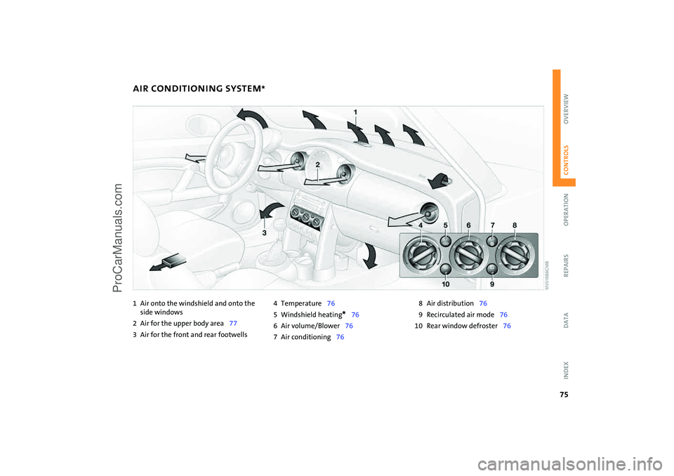
1Air onto the windshield and onto the
side windows 2 Air for the upper body area
77
3 Air for the front and rear footwells
4 Temperature
76
5 Windshield heating
* 76
6 Air volume/Blower
76
7 Air conditioning
76
8 Air distribution
76
9 Recirculated air mode
76
10 Rear window defroster
76
ProCarManuals.com
Page 78 of 165
76
AIR CONDITIONING SYSTEM
*
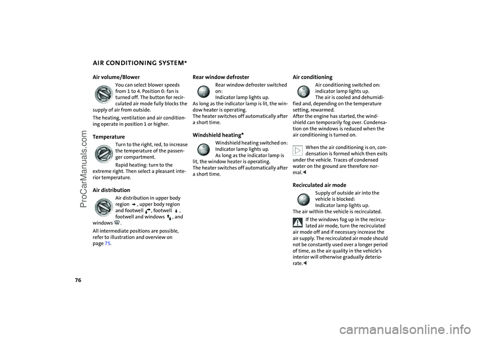
Air volume/Blower
You can select blower speeds from 1 to 4. Position
0: fan is
turned off. The button for recir
-
culated air mode fully blocks the
supply of air from outside.
The heating, ventilation and air condition
-
ing operate in position 1 or higher.Temperature
Turn to the right, red, to increase the temperature of the passen
-
ger compartment.Rapid heating: turn to the
extreme right. Then select a pleasant inte
-
rior temperature.Air distribution
Air distribution in upper body region
, upper body region
and footwell
, footwell
,
footwell and windows
, and
windows
.
All intermediate positions are possible,
refer to illustration and overview on
page
75.
Rear window defroster
Rear window defroster switched on:
Indicator lamp lights up.
As long as the indicator lamp is lit, the win
-
dow heater is operating.
The heater switches off automatically after
a short time.Windshield heating*
Windshield heating switched on:
Indicator lamp lights up.
As long as the indicator lamp is
lit, the window heater is operating.
The heater switches off automatically after
a short time.
Air conditioning
Air conditioning switched on: indicator lamp lights up.
The air is cooled and dehumidi
-
fied and, depending on the temperature
setting, rewarmed.
After the engine has started, the wind
-
shield can temporarily fog over. Condensa
-
tion on the windows is reduced when the
air conditioning is turned on.
When the air conditioning is on, con
-
densation is formed which then exits
under the vehicle. Traces of condensed
water on the ground are therefore nor
-
mal.
Indicator lamp lights up.
The air within the vehicle is recirculated.
If the windows fog up in the recircu
-
lated air mode, turn the recirculated
air mode off and if necessary increase the
air supply. The recirculated air mode should
not be constantly used over a longer period
of time, as the air quality in the vehicle's
interior will otherwise gradually deterio
-
rate.<
ProCarManuals.com
Page 79 of 165
77
OVERVIEW REPAIRS OPERATIONCONTROLS DATA INDEX
AIR CONDITIONING SYSTEM
*
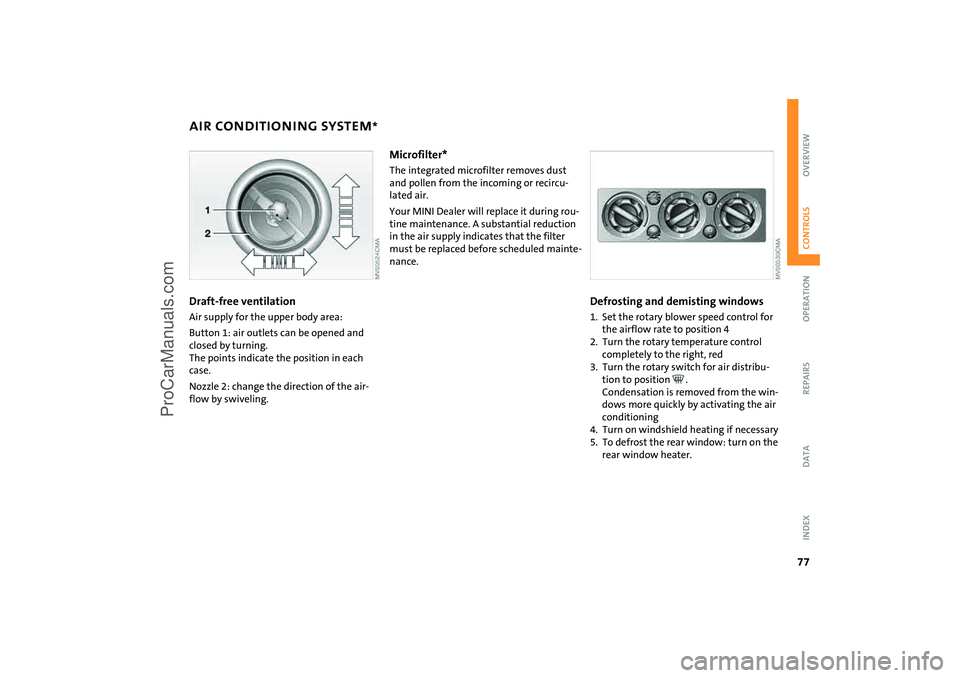
Draft-free ventilation Air supply for the upper body area:Button
1: air outlets can be opened and
closed by turning.
The points indicate the position in each
case.Nozzle
2: change the direction of the air
-
flow by swiveling.
Microfilter* The integrated microfilter removes dust
and pollen from the incoming or recircu
-
lated air.Your MINI Dealer will replace it during rou
-
tine maintenance. A substantial reduction
in the air supply indicates that the filter
must be replaced before scheduled mainte
-
nance.
Defrosting and demisting windows1. Set the rotary blower speed control for
the airflow rate to position
4
2. Turn the rotary temperature control
completely to the right, red3. Turn the rotary switch for air distribu
-
tion to position
.
Condensation is removed from the win
-
dows more quickly by activating the air
conditioning
4. Turn on windshield heating if necessary5. To defrost the rear window: turn on the
rear window heater.
ProCarManuals.com
Page 80 of 165

78
1 Air onto the windshield and onto the
side windows2 Air for the upper body area
80
3 Air for the front and rear footwells4 Rear window defroster and windshield
heating
* 79
5 Interior temperature sensor, please keep
clear and unobstructed6 Recirculated air mode
79
7 Air conditioning
76
8 Automatic air distribution and
volume
79
9 Defrosting and demisting the windshield
and side windows
80
10 Temperature
79
11 Display for air temperature and air
volume
79
12 Air volume/Blower, switching air con
-
ditioner on/off
79
13 Individual air distribution
80
AUTOMATIC CLIMATE CONTROL
*
ProCarManuals.com