ECU MINI COOPER 2014 User Guide
[x] Cancel search | Manufacturer: MINI, Model Year: 2014, Model line: COOPER, Model: MINI COOPER 2014Pages: 230, PDF Size: 11.58 MB
Page 104 of 230

Camera
The camera is located near the base of the mir‐
ror.
Keep the windshield in the area behind the in‐
terior rearview mirror clean and clear.
Switching on/off
Switching on automatically
The system is automatically active every time
the engine is started using the Start/Stop but‐
ton.
Switching on/off manually Press the button: the menu for the in‐
telligent safety system is displayed. Ad‐
justments can be made. The individual settings
are stored for the remote control currently in
use.
Press the button briefly:
▷Intelligent Safety systems are individually
switched off according to individual setting.▷The LED lights up orange.
Press the button again:
▷All Intelligent Safety systems are switched
on.▷The LED lights up green.
Hold the button down:
▷All Intelligent Safety systems are switched
off.▷The LED goes out.Warning with braking function
Note Adapting your speed and driving style
The warning does not relieve the driver of
the responsibility to adapt his or her driving
speed and style to the traffic conditions. ◀
Display
If a collision with a person detected in this way
is imminent, a warning symbol appears on the
instrument cluster and in the Head-up Display.
The red symbol is displayed and a signalsounds.
Intervene immediately by braking or
making an evasive maneuver.
Braking intervention
The warning prompts the driver himself to in‐
tervene. During a warning, the maximum brak‐ ing force is used. A prerequisite for the brake
booster is a sufficiently fast and sufficiently
strong actuation of the brake pedal. In addi‐
tion, if there is a risk of collision, the system can
assist with a slight braking intervention. The in‐
tervention can bring a vehicle traveling at slow
speed to a complete stop.
Manual transmission: During a braking inter‐ vention up until reaching a complete stop, the
engine may be shut down.
The braking intervention is executed only if DSC
Dynamic Stability Control is switched on and
Dynamic Traction Control DTC is activated.
The braking intervention can be interrupted by
pressing on the accelerator pedal or by actively
moving the steering wheel.
Tow-starting and towing
When tow-starting and towing the vehi‐
cle, switch off the Intelligent Safety systems;
otherwise, improper behavior of the braking
function of individual systems could result in an
accident. ◀Seite 104CONTROLSSafety104
Online Edition for Part no. 01 40 2 927 905 - II/14
Page 133 of 230

Interior equipmentVehicle equipmentAll standard, country-specific and optional
equipment that is offered in the model series is
described in this chapter. Therefore, equipment
is also described that is not available in a vehi‐
cle, e. g., because of the selected optional
equipment or country variant. This also applies
for safety-related functions and systems.
Universal garage dooropener
The concept
The universal garage door opener can operate
up to 3 functions of remote-controlled systems
such as garage door drives or lighting systems.
The universal garage door opener replaces up
to 3 different hand-held transmitters. To oper‐
ate the remote control, the buttons on the inte‐
rior rearview mirror must be programmed with
the desired functions. The hand-held transmit‐
ter for the particular system is required in order
to program the remote control.
During programming
During programming and before activat‐
ing a device using the integrated universal re‐
mote control, ensure that there are no people,
animals, or objects in the range of movement
of the remote-controlled device; otherwise,
there is a risk of injury or damage.
Also follow the safety instructions of the hand-
held transmitter. ◀
Before selling the vehicle, delete the stored
functions for the sake of security.Compatibility
If this symbol is printed on the packag‐
ing or in the instructions of the system
to be controlled, the system is generally
compatible with the universal garage door
opener.
If you have any questions, please contact:▷Your service center.▷www.homelink.com on the Internet.
HomeLink is a registered trademark of Johnson
Controls, Inc.
At a glance
1LED2Programmable keys3Hand-held transmitters of the system
Programming
General information
1.Switch on the ignition.2.Initial setup:
Press and hold the left and right button on
the interior rearview mirror simultaneously
for approximately 20 seconds until the LED
on the interior rearview mirror flashes. This
erases all programming of the buttons on
the interior rearview mirror.Seite 133Interior equipmentCONTROLS133
Online Edition for Part no. 01 40 2 927 905 - II/14
Page 139 of 230

2.Pull the cargo cover out of the brackets on
the left and right.
Installing cargo cover
1.Slide the cover forward horizontally into the
two side brackets until it audibly latches.2.Attach the left and right retaining straps at
the tailgate.
Enlarging the cargo area
General information
The cargo area can be enlarged by folding
down the rear seat backrest.
The rear seat backrest is divided into two parts
at a ratio of 60 to 40. The backrest of the right
seat is connected to the backrest center sec‐
tion.
Hints Danger of pinching
Before folding down the rear seat back‐
rests, ensure that the area of movement of the
backrests is clear. Ensure that no one is located
in or reaches into the area of movement of the
rear seat backrests. Otherwise, injury or dam‐
age may result. ◀
Push the headrests down, before the
backrests are folded down
Before folding down the rear seat backrests,
make sure that the corresponding headrest is
pushed all the way down; otherwise, damage
may result. ◀
Folding down rear seat backrest
The rear seat backrests can be folded down
from the front or from the cargo area.
Before the backrest is folded down, hook the
corresponding safety belt into the safety belt
on the side.
Pull the release upward and fold the backrest
toward the front.
Folding back the backrest Ensure that the lock is securely engaged
When folding back the backrest, make
sure that it securely locks in place. When this
happens the red warning field on the seat dis‐
appears. If the backrest is not properly en‐
gaged, transported cargo could enter the pas‐
senger compartment during braking or evasive
maneuvers and endanger the vehicle occu‐
pants. ◀
Fold up the backrest and press it into the latch.
Make sure that the safety belt is not pinched.
Adjusting the backrest tilt To transport bulky items, the cargo area can be
expanded by setting the backrests at a steeper
angle.
1.Released the back rest, and tilt it forward.Seite 139Interior equipmentCONTROLS139
Online Edition for Part no. 01 40 2 927 905 - II/14
Page 141 of 230

Storage compartmentsVehicle equipment
All standard, country-specific and optional
equipment that is offered in the model series is
described in this chapter. Therefore, equipment
is also described that is not available in a vehi‐
cle, e. g., because of the selected optional
equipment or country variant. This also applies
for safety-related functions and systems.
At a glance
The following storage compartments are avail‐
able in the vehicle interior:▷Storage compartment in front of the cu‐
pholders.▷Storage tray in the center console.▷Glove compartment on the front passenger
side.▷Storage compartment above the glove
compartment.▷Storage compartment in the center arm‐
rest.▷Compartments in the doors.▷Pockets on the backrests of the front seats.▷Net underneath the center console in the
footwell of the front seat passenger.
Safety information
No loose objects in the passenger com‐
partment
Do not stow any objects in the passenger com‐
partment without securing them; otherwise,
they may present a danger to occupants for in‐
stance during braking and avoidance maneu‐
vers. ◀
Do not place anti-slip mats on the dash‐
board
Do not place anti-slip mats on the dashboard.
The mat materials could damage the dash‐
board. ◀
Glove compartment
Opening
Pull the handle.
The light in the glove compartment switches
on.
Close the glove compartment again im‐
mediately
Close the glove compartment immediately after
use while driving; otherwise, injury may occur
during accidents. ◀
Closing Fold up the cover.
Seite 141Storage compartmentsCONTROLS141
Online Edition for Part no. 01 40 2 927 905 - II/14
Page 143 of 230

Rear
In front of the back seats and in the side armr‐
ests.
Clothes hooks The clothes hooks are located above the side
windows in the rear.
Do not obstruct view
When suspending clothing from the
hooks, ensure that it will not obstruct the driv‐
er's vision. ◀
No heavy objects
Do not hang heavy objects from the
hooks; otherwise, they may present a danger to passengers during braking and evasive ma‐neuvers. ◀
Storage space under the
cargo floor panel
Located under the cargo floor panel on the
right side is a trough for the onboard vehicle
tool kit.
To remove the onboard vehicle tool kit, fold the
right side of the cargo area floor upward.
Variable cargo areafloor
With the variable cargo area floor, the cargo
area can be configured corresponding to trans‐
port requirements. To do this, remove the
cargo area floor, and insert it in the desired po‐
sition.
Follow the instructions for securing cargo, refer
to page 151.
Lower position
▷Larger objects can be transported.▷Space for smaller objects remains between
the fixed and variable cargo area floor.Seite 143Storage compartmentsCONTROLS143
Online Edition for Part no. 01 40 2 927 905 - II/14
Page 144 of 230

Folded up positionThe variable cargo area may not be used
as a partition net to separate the cargo
area and the passenger compartment.▷Only use the variable cargo floor in the
folded-up position when the backrests are
folded up and locked.▷Always secure cargo against shifting, using
straps, belts and lashing eyes, for example.
If you do not observe this precaution, you can
endanger vehicle occupants and damage the
cargo floor during braking. ◀
Fold up the variable loading floor in the lower
position, and push it behind the locks on the
left and right, arrow.
▷The maximum cargo area height is ach‐
ieved.▷The cargo net can be loaded with light‐
weight and flat objects.
Upper position
▷With the backrests folded down, a long, flat
loading surface is produced.Maximum load in this position:
330 lbs/150 kg.▷Space for objects remains between the
fixed and variable cargo area floor.Seite 144CONTROLSStorage compartments144
Online Edition for Part no. 01 40 2 927 905 - II/14
Page 150 of 230

Objects in the area around the pedalsNo objects in the area around the pedals
Keep floor mats, carpets, and any other
objects out of the area of motion of the pedals;
otherwise, the function of the pedals could be
impeded while driving and create the risk of an
accident.
Do not place additional floor mats over existing
mats or other objects.
Only use floor mats that have been approved for the vehicle and can be properly fixed in
place.
Ensure that the floor mats are securely fastened
again after they were removed for cleaning, for
example. ◀
Driving in wet conditions When roads are wet or there is heavy rain,
briefly exert gentle pressure on the brake pedal
every few miles.
Ensure that this action does not endanger other
road users.
The heat generated in this process helps dry
the brake discs and pads.
In this way braking efficiency will be available
when you need it.
HillsDrive long or steep downhill gradients in the
gear in which the least braking is required. Oth‐
erwise, the brake system may overheat, result‐
ing in a reduction in the brake system effi‐
ciency.
You can increase the engine's braking effect by
shifting down, going all the way to first gear, if
necessary.
Avoid load on the brakes
Avoid placing excessive load on the brake
system. Light but consistent brake pressure can
lead to high temperatures, brake wear and
possibly even brake failure. ◀Do not drive in neutral
Do not drive in neutral or with the engine
stopped, as doing so disables engine braking.
In addition, steering and brake assist are un‐
available with the engine stopped. ◀
Brake disc corrosion Corrosion on the brake discs and contamina‐
tion on the brake pads are furthered by:▷Low mileage.▷Extended periods when the vehicle is not
used at all.▷Infrequent use of the brakes.
Corrosion occurs when the minimum pressure
that must be exerted by the pads during brake
applications to clean the discs is not reached.
Should corrosion form on the brake discs, the
brakes will tend to respond with a pulsating ef‐
fect that generally cannot be corrected.
Condensation under the parked vehicle
When using the automatic climate control, con‐
densation water develops that exits under‐
neath the vehicle.
Traces of water under the vehicle like this are
normal.
Ground clearance Limited ground clearance
Observe the limited ground clearance of
the vehicle, e. g. while entering underground
parking garages or when driving over obsta‐
cles. Otherwise, damages to the vehicle may
result. ◀
Seite 150DRIVING TIPSThings to remember when driving150
Online Edition for Part no. 01 40 2 927 905 - II/14
Page 151 of 230

LoadingVehicle equipment
All standard, country-specific and optional
equipment that is offered in the model series is
described in this chapter. Therefore, equipment
is also described that is not available in a vehi‐
cle, e. g., because of the selected optional
equipment or country variant. This also applies
for safety-related functions and systems.
Hints Overloading the vehicle
To avoid exceeding the approved carry‐
ing capacity of the tires, never overload the ve‐
hicle. Overloading can lead to overheating and
increases the rate at which damage develops
inside the tires. This could result in a sudden
loss of tire inflation pressure. ◀
No fluids in the trunk
Make sure that fluids do not leak into the
trunk; otherwise, the vehicle may be dam‐
aged. ◀
Heavy and hard objects
Do not stow any heavy and hard objects
in the passenger compartment without secur‐
ing them; otherwise, they may present a dan‐
ger to occupants, e.g., during braking and eva‐
sive maneuvers. ◀Determining the load
limit1.Locate the following statement on your ve‐
hicle’s placard:▷The combined weight of occupants and
cargo should never exceed XXX kg or
YYY lbs. Otherwise, damage to the ve‐
hicle and unstable driving situations
may result.2.Determine the combined weight of the
driver and passengers that will be riding in
your vehicle.3.Subtract the combined weight of the driver
and passengers from XXX kilograms or YYY
pounds.4.The resulting figure equals the available
amount of cargo and luggage load ca‐
pacity.
For example, if the YYY amount equals
1,000 lbs and there will be four 150 lbs pas‐
sengers in your vehicle, the amount of
available cargo and luggage load capacity
is 400 lbs: 1,000 lbs minus 600 lbs =
400 lbs.5.Determine the combined weight of luggage
and cargo being loaded on the vehicle.
That weight may not safely exceed the
available cargo and luggage load capacity
calculated in Step 4.Seite 151LoadingDRIVING TIPS151
Online Edition for Part no. 01 40 2 927 905 - II/14
Page 152 of 230

Load
The maximum load is the sum of the weight of
the occupants and the cargo.
The greater the weight of the occupants, the
less cargo that can be transported.
Stowing cargo
▷Cover sharp edges and corners on the
cargo.▷Heavy cargo: stow as far forward as possi‐
ble, directly behind and at the bottom of
the rear passenger seat backrests.▷Very heavy cargo: when the rear seat is not
occupied, secure each of the outer safety
belts in the opposite buckle.▷If necessary, fold down the rear backrests
to stow cargo.▷Do not stack cargo above the top edge of
the backrests.Securing cargo
Lashing eyes in the cargo area
Without storage compartment package: to se‐
cure the cargo there are two lashing eyes, ar‐
row 1, in the cargo area.
With storage compartment package: to secure
the cargo there are six lashing eyes, arrows 1
and 2, in the cargo area.
Securing cargo
▷Smaller and lighter items: secure with re‐
taining straps or with draw straps.▷Larger and heavy objects: secure with
cargo straps.
Attach the cargo straps, retaining straps or
draw straps to the lashing eyes in the cargo
area.
Securing cargo
Stow and secure the cargo as described
above; otherwise it may present a danger to
the occupants, e.g., during braking and avoid‐
ance maneuvers. ◀
Roof-mounted luggage
rack
Note Installation only possible with roof rack.
Roof racks are available as special accessories.
Seite 152DRIVING TIPSLoading152
Online Edition for Part no. 01 40 2 927 905 - II/14
Page 153 of 230
Securing
Follow the installation instructions of the roof
rack.
Loading Be sure that adequate clearance is maintained
for tilting and opening the glass sunroof.
Because roof racks raise the vehicle's center of
gravity when loaded, they have a major effect
on vehicle handling and steering response.
Therefore, note the following when loading and
driving:▷Do not exceed the approved roof/axle
loads and the approved gross vehicle
weight.▷Distribute the roof load uniformly.▷The roof load should not be too large in
area.▷Always place the heaviest pieces on the
bottom.▷Secure the roof luggage firmly, e.g., tie with
ratchet straps.▷Do not let objects project into the opening
path of the tailgate.▷Drive cautiously and avoid sudden acceler‐
ation and braking maneuvers. Take corners
gently.
Rear luggage rack
General information Installation only possible with rear luggage rack
preparation.
Rear racks are available as special accessories.
Note Follow the installation instructions of the rear
luggage rack.
Drive cautiously and avoid sudden acceleration
and braking maneuvers. Take corners gently.
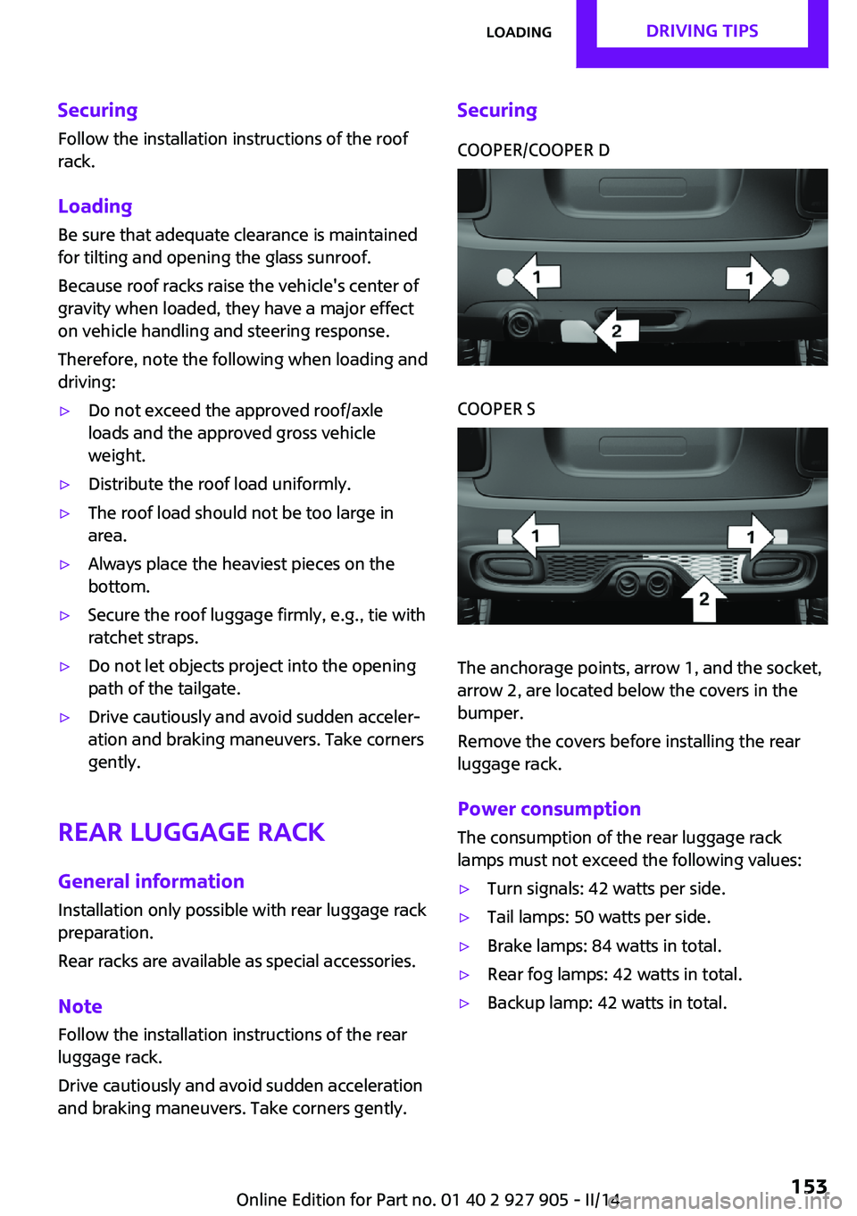
SecuringCOOPER/COOPER DCOOPER S
The anchorage points, arrow 1, and the socket,
arrow 2, are located below the covers in the
bumper.
Remove the covers before installing the rear
luggage rack.
Power consumption
The consumption of the rear luggage rack
lamps must not exceed the following values:
▷Turn signals: 42 watts per side.▷Tail lamps: 50 watts per side.▷Brake lamps: 84 watts in total.▷Rear fog lamps: 42 watts in total.▷Backup lamp: 42 watts in total.Seite 153LoadingDRIVING TIPS153
Online Edition for Part no. 01 40 2 927 905 - II/14