engine MINI COOPER 2014 Owner's Manual
[x] Cancel search | Manufacturer: MINI, Model Year: 2014, Model line: COOPER, Model: MINI COOPER 2014Pages: 230, PDF Size: 11.58 MB
Page 75 of 230
▷When the ignition is switched on, the trip
odometer is reset.
External temperature
If the indicator drops to
+37 ℉/+3 ℃, a signal sounds.
A Check Control message is dis‐
played.
There is an increased risk of ice
on roads.
Ice on roads
Even at temperatures above
+37 ℉/+3 ℃, there can be a risk of ice on
roads.
Therefore, drive carefully on bridges and
shaded roads, for example, to avoid the in‐
creased risk of an accident. ◀
Time The time is displayed in the in‐
strument cluster.
Setting the time on the Control
Display, refer to page 81.
Date The date is displayed in the in‐
strument cluster.
Set the date on the Control Dis‐
play, refer to page 82.
Range
Display After the reserve range is
reached:▷A Check Control message is
displayed briefly.▷The remaining range is
shown on the onboard com‐
puter.▷When a dynamic driving style is used, such
as when cornering quickly, operation of the
engine is not always ensured.
The Check Control message appears continu‐
ously below a range of approx. 30 miles/50 km.
Refuel promptly
Refuel no later than at a range of
30 miles/50 km, or operation of the engine is
not ensured and damage may occur. ◀
Displaying the cruising range
1. "Settings"2."Instr. cluster display"3."Range"
Current fuel consump‐
tion
The concept
Displays the current fuel consumption. You can
check whether you are currently driving in an
efficient and environmentally-friendly manner.
Displaying the current fuel
consumption
1. "Settings"2."Instr. cluster display"3."Current consumption"Seite 75DisplaysCONTROLS75
Online Edition for Part no. 01 40 2 927 905 - II/14
Page 79 of 230
Activating a list and adjusting the
settingButton the steering wheelFunctionActivate the corre‐
sponding list, and se‐
lect the desired set‐
ting.Confirm the selection.
Computer
Calling up information on the info
display
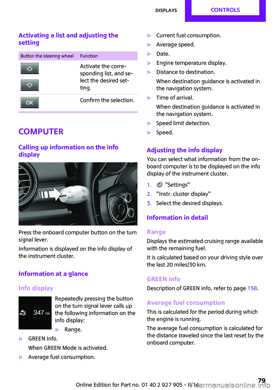
Press the onboard computer button on the turn
signal lever.
Information is displayed on the info display of
the instrument cluster.
Information at a glance
Info display Repeatedly pressing the button
on the turn signal lever calls up
the following information on the
info display:
▷Range.▷GREEN Info.
When GREEN Mode is activated.▷Average fuel consumption.▷Current fuel consumption.▷Average speed.▷Date.▷Engine temperature display.▷Distance to destination.
When destination guidance is activated in
the navigation system.▷Time of arrival.
When destination guidance is activated in
the navigation system.▷Speed limit detection.▷Speed.
Adjusting the info display
You can select what information from the on‐
board computer is to be displayed on the info
display of the instrument cluster.
1. "Settings"2."Instr. cluster display"3.Select the desired displays.
Information in detail
Range
Displays the estimated cruising range available
with the remaining fuel.
It is calculated based on your driving style over
the last 20 miles/30 km.
GREEN info Description of GREEN info, refer to page 158.
Average fuel consumption
This is calculated for the period during which
the engine is running.
The average fuel consumption is calculated for
the distance traveled since the last reset by the
onboard computer.
Seite 79DisplaysCONTROLS79
Online Edition for Part no. 01 40 2 927 905 - II/14
Page 80 of 230
Average speed
Periods in which the vehicle is parked with the
engine manually stopped are not included in
the calculation of the average speed.
Resetting average valuesPress and hold the onboard computer button
on the turn signal lever.
Distance to destination The distance remaining to the destination is
displayed if a destination is entered in the navi‐
gation system before the trip is started.
The distance to the destination is adopted au‐
tomatically.
Time of arrival The estimated time of arrival is displayed if a
destination is entered in the navigation system
before the trip is started.
The time must be correctly set.
Speed limit detection
Description of the speed limit detection, refer
to page 77, function.
Trip computer
The vehicle features two types of computer.▷"Onboard info": the values can be reset as
often as necessary.▷"Trip computer": the values provide an
overview of the current trip.
Resetting the trip computer
1. "Vehicle Info"2."Trip computer"3."Reset": all values are reset.
"Automatically reset": all values are reset
approx. 4 hours after the vehicle comes to
a standstill.Display on the Control Display
Display the onboard computer or trip computer
on the Control Display.1. "Vehicle Info"2."Onboard info" or "Trip computer"
Resetting the fuel consumption and
speed
1. "Vehicle Info"2."Onboard info"3."Consumpt." or "Speed"4."Yes"
Driving Excitement
The concept
On the Control Display, sport instruments can
be displayed, and the vehicle condition can be
checked before the use of the SPORT program.
Sport instruments On the Control Display, values for power and
torque are displayed.
Displaying sport instruments
Via onboard monitor:
1. "Vehicle Info"2."Driving Excitement"3. "Sports instruments"
Via the Driving Dynamics Control
1.Activating SPORT.2. "Driving Excitement"3. "Sports instruments"
Vehicle state
The following vehicle and surrounding area
data are automatically checked and evaluated
in succession:
▷Range.Seite 80CONTROLSDisplays80
Online Edition for Part no. 01 40 2 927 905 - II/14
Page 81 of 230

▷Engine temperature.▷External temperature.▷SPORT program state.
Finally, a total evaluation of the vehicle state is
displayed.
Checking vehicle state
Via onboard monitor:
1. "Vehicle Info"2."Driving Excitement"3. "Vehicle and surroundings"
Via the Driving Dynamics Control
1.Activating SPORT.2. "Driving Excitement"3. "Vehicle and surroundings"
Speed warning
The concept
Display of a speed limit which, when reached,
should cause a warning to be issued.
The warning is repeated if the vehicle speed
drops below the set speed limit once by at least
3 mph/5 km/h.
Displaying, setting or changing the
limit
1. "Settings"2."Speed"3."Warning at:"4.Turn the controller until the desired limit is
displayed.5.Press the controller.
The speed limit is stored.
Activating/deactivating the limit
1. "Settings"2."Speed"3."Warning"4.Press the controller.
Setting your current speed as the limit
1. "Settings"2."Speed"3."Select current speed"4.Press the controller.
The current vehicle speed is stored as the
limit.
Settings on the Control
Display
Time
Setting the time zone
1. "Settings"2."Time/Date"3."Time zone"4.Select the desired time zone.
The time zone is stored.
Setting the time
1. "Settings"2."Time/Date"3."Time:"4.Turn the controller until the desired hours
are displayed.5.Press the controller.6.Turn the controller until the desired mi‐
nutes are displayed.7.Press the controller.
The time is stored.
Setting the time format
1. "Settings"2."Time/Date"Seite 81DisplaysCONTROLS81
Online Edition for Part no. 01 40 2 927 905 - II/14
Page 86 of 230
LampsVehicle equipmentAll standard, country-specific and optional
equipment that is offered in the model series is
described in this chapter. Therefore, equipment
is also described that is not available in a vehi‐
cle, e. g., because of the selected optional
equipment or country variant. This also applies
for safety-related functions and systems.
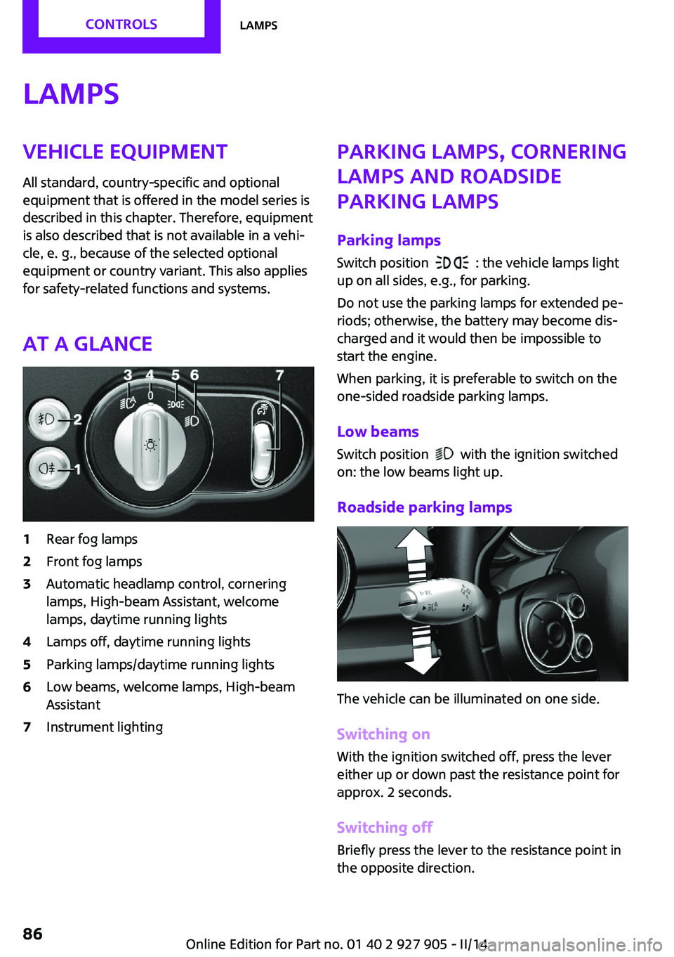
At a glance1Rear fog lamps2Front fog lamps3Automatic headlamp control, cornering
lamps, High-beam Assistant, welcome
lamps, daytime running lights4Lamps off, daytime running lights5Parking lamps/daytime running lights6Low beams, welcome lamps, High-beam
Assistant7Instrument lightingParking lamps, cornering
lamps and roadside
parking lamps
Parking lamps Switch position
: the vehicle lamps light
up on all sides, e.g., for parking.
Do not use the parking lamps for extended pe‐
riods; otherwise, the battery may become dis‐
charged and it would then be impossible to
start the engine.
When parking, it is preferable to switch on the
one-sided roadside parking lamps.
Low beams
Switch position
with the ignition switched
on: the low beams light up.
Roadside parking lamps
The vehicle can be illuminated on one side.
Switching on With the ignition switched off, press the lever
either up or down past the resistance point for
approx. 2 seconds.
Switching off Briefly press the lever to the resistance point in
the opposite direction.
Seite 86CONTROLSLamps86
Online Edition for Part no. 01 40 2 927 905 - II/14
Page 95 of 230

All wheels greenSystem is active and will issue a warning rela‐
tive to the tire inflation pressures stored during
the last reset.
One wheel is yellow
A flat tire or major drop in inflation pressure in
the indicated tire.
All wheels are yellow
A flat tire or major drop in inflation pressure in
several tires.
Wheels, gray
The system cannot detect a flat tire due to a
malfunction.
Status information
The status display additionally shows the cur‐
rent tire inflation pressures. The values shown
are current measurement values and may vary
depending on driving style or weather condi‐
tions.
Carry out reset
Reset the system after each adjustment of the
tire inflation pressure and after every tire or
wheel change.1."Vehicle Info"2."Vehicle status"3. "Perform reset"4.Start the engine - do not drive away.5.Reset the tire pressure using "Perform
reset".6.Drive away.
The tires are shown in gray and the status is
displayed.
After driving faster than 19 mph/30 km/h for a
short period, the tire inflation pressures set are
accepted as reference values. The resetting
process is completed automatically during driv‐
ing. After successful completion of the reset,
the tires appear in green on the Control Display
and "Tire Pressure Monitor (TPM) active" is dis‐
played.
The progress of the reset is displayed.
The trip can be interrupted at any time. If you
drive away again, the reset resumes automati‐
cally.
Low tire pressure message The yellow warning lamp lights up. A
Check Control message is displayed.▷There is a flat tire or a major loss in
tire inflation pressure.▷A reset of the system was not carried out
after a wheel was changed. The system
therefore issues a warning based on the tire
pressures before the last reset.1.Reduce your speed and stop cautiously.
Avoid sudden braking and steering maneu‐
vers.2.Check whether the vehicle is fitted with
regular tires or run-flat tires.
Run-flat tires, refer to page 175, are la‐
beled with a circular symbol containing the
letters RSC marked on the tire sidewall.
Do not continue driving without run-flat
tires
Do not continue driving if the vehicle is not
equipped with run-flat tires; continued driving
may result in serious accidents. ◀
When a low inflation pressure is indicated, DSC
Dynamic Stability Control is switched on if nec‐
essary.
Actions in the event of a flat tire Normal tires
1.Identify the damaged tire.
Do this by checking the air pressure in all
four tires.Seite 95SafetyCONTROLS95
Online Edition for Part no. 01 40 2 927 905 - II/14
Page 98 of 230
It detects a pressure loss in a tire by comparing
the rotational speeds of the individual wheels
while moving.
In the event of a pressure loss, the diameter
and therefore the rotational speed of the corre‐
sponding wheel change. This is detected and
reported as a flat tire.
Functional requirements The system must have been initialized when
the tire inflation pressure was correct; other‐
wise, reliable signaling of a flat tire is not en‐
sured. Initialize the system after each correc‐
tion of the tire inflation pressure and after
every tire or wheel change.
Status display
The current status of the Flat Tire Monitor can
be displayed on the Control Display, e.g.,
whether or not the FTM is active.1."Vehicle Info"2."Vehicle status"3. "Flat Tire Monitor (FTM)"
The status is displayed.
Initialization The initialization process adopts the set infla‐
tion tire pressures as reference values for the
detection of a flat tire. Initialization is started by
confirming the inflation pressures.
Do not initialize the system when driving with
snow chains.
1."Vehicle Info"2."Vehicle status"3. "Perform reset"4.Start the engine - do not drive away.5.Start the initialization with "Perform reset".6.Drive away.
The initialization is completed while driving,
which can be interrupted at any time.
The initialization automatically continues when
driving resumes.
Indication of a flat tire The yellow warning lamp lights up. A
Check Control message is displayed.
There is a flat tire or a major loss in tire
inflation pressure.1.Reduce your speed and stop cautiously.
Avoid sudden braking and steering maneu‐
vers.2.Check whether the vehicle is fitted with
regular tires or run-flat tires.
Run-flat tires, refer to page 175, are la‐
beled with a circular symbol containing the
letters RSC marked on the tire sidewall.
Do not continue driving without run-flat
tires
Do not continue driving if the vehicle is not
equipped with run-flat tires; continued driving
may result in serious accidents. ◀
When a flat tire is indicated, DSC Dynamic Sta‐
bility Control is switched on if necessary.
System limits Sudden tire damage
Sudden serious tire damage caused by
external influences cannot be indicated in ad‐
vance. ◀
A natural, even pressure loss in all four tires
cannot be detected. Therefore, check the tire
inflation pressure regularly.
The system could be delayed or malfunction in
the following situations:
▷When the system has not been initialized.▷When driving on a snowy or slippery road
surface.▷Sporty driving style: slip in the drive wheels,
high lateral acceleration.▷When driving with snow chains.Seite 98CONTROLSSafety98
Online Edition for Part no. 01 40 2 927 905 - II/14
Page 100 of 230
NotePersonal responsibility
The system does not serve as a substitute
for the driver's personal judgment of the traffic
situation.
Be aware of the traffic situation and the vehi‐
cle's surroundings at all times, otherwise an ac‐ cident is still possible despite all warnings. ◀
At a glance
Button in the vehicle
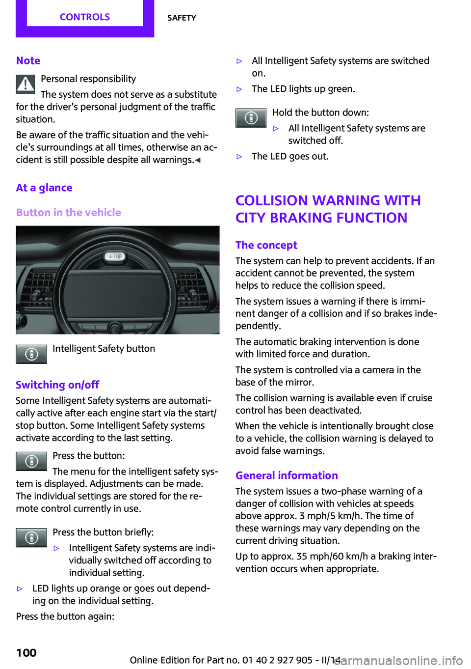
Intelligent Safety button
Switching on/off Some Intelligent Safety systems are automati‐
cally active after each engine start via the start/
stop button. Some Intelligent Safety systems
activate according to the last setting.
Press the button:
The menu for the intelligent safety sys‐
tem is displayed. Adjustments can be made.
The individual settings are stored for the re‐
mote control currently in use.
Press the button briefly:
▷Intelligent Safety systems are indi‐
vidually switched off according to
individual setting.▷LED lights up orange or goes out depend‐
ing on the individual setting.
Press the button again:
▷All Intelligent Safety systems are switched
on.▷The LED lights up green.
Hold the button down:
▷All Intelligent Safety systems are
switched off.▷The LED goes out.
Collision warning with
City Braking function
The concept
The system can help to prevent accidents. If an
accident cannot be prevented, the system
helps to reduce the collision speed.
The system issues a warning if there is immi‐
nent danger of a collision and if so brakes inde‐
pendently.
The automatic braking intervention is done
with limited force and duration.
The system is controlled via a camera in the
base of the mirror.
The collision warning is available even if cruise
control has been deactivated.
When the vehicle is intentionally brought close to a vehicle, the collision warning is delayed to
avoid false warnings.
General information The system issues a two-phase warning of a
danger of collision with vehicles at speeds
above approx. 3 mph/5 km/h. The time of
these warnings may vary depending on the
current driving situation.
Up to approx. 35 mph/60 km/h a braking inter‐
vention occurs when appropriate.
Seite 100CONTROLSSafety100
Online Edition for Part no. 01 40 2 927 905 - II/14
Page 101 of 230

Detection range
Vehicles are observed when they are traveling
in the same direction of movement if they are
located within the detection range of the sys‐
tem.
At a glance
Button in the vehicle
Intelligent Safety button
Camera
The camera is located near the base of the mir‐
ror.
Keep the windshield in the area behind the in‐
terior rearview mirror clean and clear.
Switching on/off
Switching on automatically
The system is automatically active every time
the engine is started using the Start/Stop but‐
ton.
Switching on/off manually Press the button: the menu for the in‐
telligent safety system is displayed. Ad‐
justments can be made. The individual settings
are stored for the remote control currently in
use.
Press the button briefly:▷Intelligent Safety systems are individually
switched off according to individual setting.▷The LED lights up orange.
Press the button again:
▷All Intelligent Safety systems are switched
on.▷The LED lights up green.
Hold the button down:
▷All Intelligent Safety systems are switched
off.▷The LED goes out.
Setting the warning time
The warning time can be set via the onboard
monitor.
1."Settings"2."Frontal Coll. Warning"3.Activate the desired warning time on the
Control Display.
The selected channel is stored for the remote
control currently in use.
Seite 101SafetyCONTROLS101
Online Edition for Part no. 01 40 2 927 905 - II/14
Page 102 of 230
Warning with braking function
Note Adapting your speed and driving style
The warning does not relieve the driver of
the responsibility to adapt his or her driving
speed and style to the traffic conditions. ◀
Display
If a collision with a vehicle detected in this way
is imminent, a warning symbol appears on the
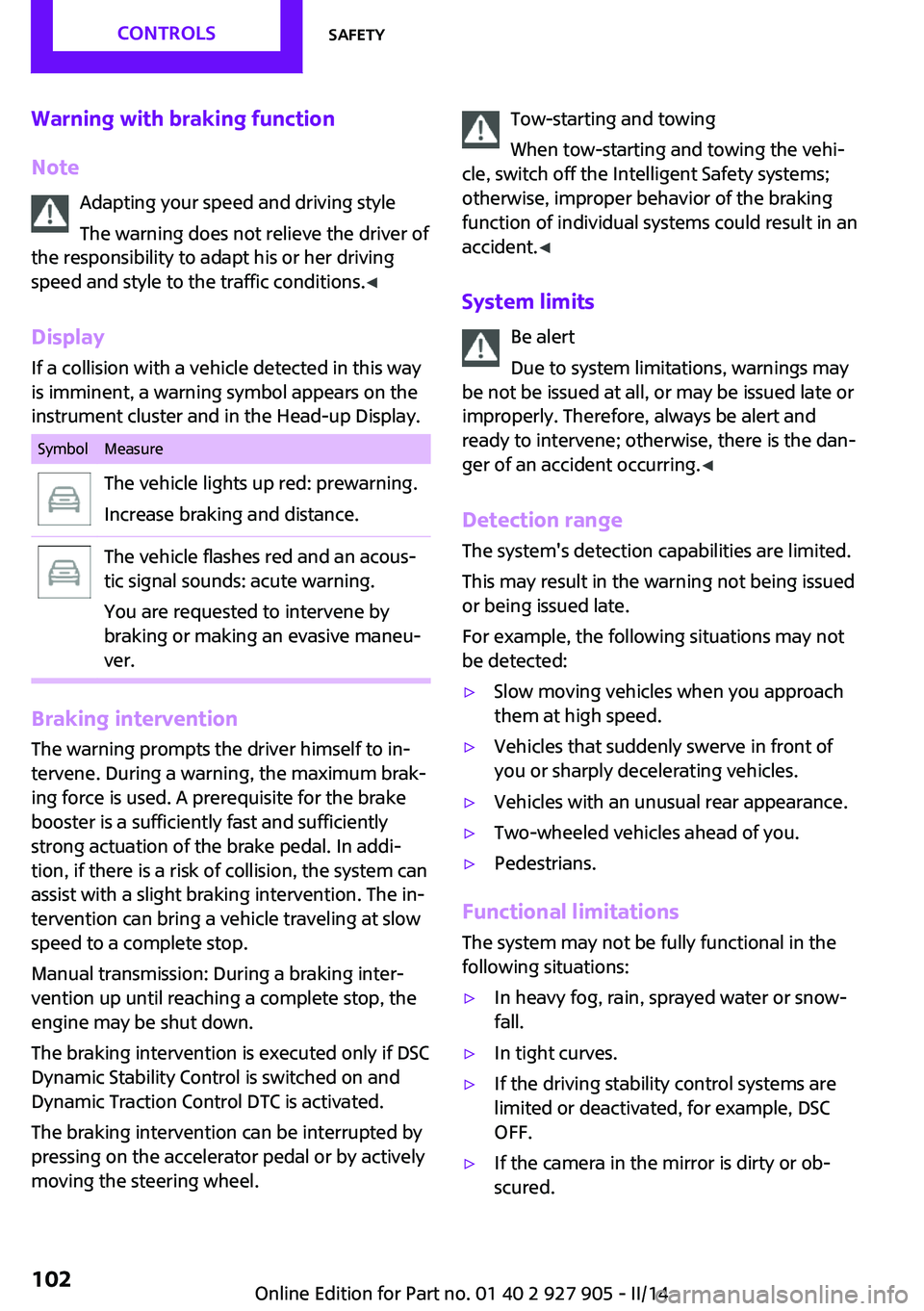
instrument cluster and in the Head-up Display.SymbolMeasureThe vehicle lights up red: prewarning.
Increase braking and distance.The vehicle flashes red and an acous‐
tic signal sounds: acute warning.
You are requested to intervene by
braking or making an evasive maneu‐
ver.
Braking intervention
The warning prompts the driver himself to in‐
tervene. During a warning, the maximum brak‐
ing force is used. A prerequisite for the brake
booster is a sufficiently fast and sufficiently
strong actuation of the brake pedal. In addi‐
tion, if there is a risk of collision, the system can
assist with a slight braking intervention. The in‐
tervention can bring a vehicle traveling at slow
speed to a complete stop.
Manual transmission: During a braking inter‐
vention up until reaching a complete stop, the
engine may be shut down.
The braking intervention is executed only if DSC
Dynamic Stability Control is switched on and
Dynamic Traction Control DTC is activated.
The braking intervention can be interrupted by
pressing on the accelerator pedal or by actively
moving the steering wheel.
Tow-starting and towing
When tow-starting and towing the vehi‐
cle, switch off the Intelligent Safety systems;
otherwise, improper behavior of the braking
function of individual systems could result in an
accident. ◀
System limits Be alert
Due to system limitations, warnings may
be not be issued at all, or may be issued late or
improperly. Therefore, always be alert and
ready to intervene; otherwise, there is the dan‐
ger of an accident occurring. ◀
Detection range The system's detection capabilities are limited.
This may result in the warning not being issued
or being issued late.
For example, the following situations may not
be detected:▷Slow moving vehicles when you approach
them at high speed.▷Vehicles that suddenly swerve in front of
you or sharply decelerating vehicles.▷Vehicles with an unusual rear appearance.▷Two-wheeled vehicles ahead of you.▷Pedestrians.
Functional limitations
The system may not be fully functional in the
following situations:
▷In heavy fog, rain, sprayed water or snow‐
fall.▷In tight curves.▷If the driving stability control systems are
limited or deactivated, for example, DSC
OFF.▷If the camera in the mirror is dirty or ob‐
scured.Seite 102CONTROLSSafety102
Online Edition for Part no. 01 40 2 927 905 - II/14