MINI COOPER 2014 Workshop Manual
Manufacturer: MINI, Model Year: 2014, Model line: COOPER, Model: MINI COOPER 2014Pages: 230, PDF Size: 11.58 MB
Page 51 of 230
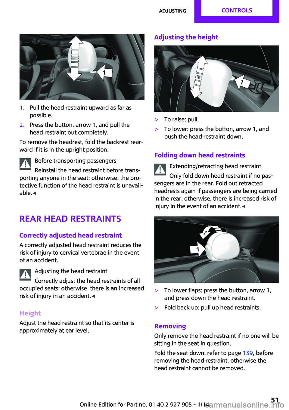
1.Pull the head restraint upward as far as
possible.2.Press the button, arrow 1, and pull the
head restraint out completely.
To remove the headrest, fold the backrest rear‐
ward if it is in the upright position.
Before transporting passengers
Reinstall the head restraint before trans‐
porting anyone in the seat; otherwise, the pro‐
tective function of the head restraint is unavail‐
able. ◀
Rear head restraints
Correctly adjusted head restraint
A correctly adjusted head restraint reduces the
risk of injury to cervical vertebrae in the event
of an accident.
Adjusting the head restraint
Correctly adjust the head restraints of all
occupied seats; otherwise, there is an increased
risk of injury in an accident. ◀
Height Adjust the head restraint so that its center is
approximately at ear level.
Adjusting the height▷To raise: pull.▷To lower: press the button, arrow 1, and
push the head restraint down.
Folding down head restraints
Extending/retracting head restraint
Only fold down head restraint if no pas‐
sengers are in the rear. Fold out retracted
headrests again if passengers are being carried
in the rear; otherwise, there is increased risk of
injury in the event of an accident. ◀
▷To lower flaps: press the button, arrow 1,
and press down the head restraint.▷Fold back up: pull up head restraints.
Removing
Only remove the head restraint if no one will be
sitting in the seat in question.
Fold the seat down, refer to page 139, before
removing the head restraint, otherwise the
head restraint cannot be removed.
Seite 51AdjustingCONTROLS51
Online Edition for Part no. 01 40 2 927 905 - II/14
Page 52 of 230
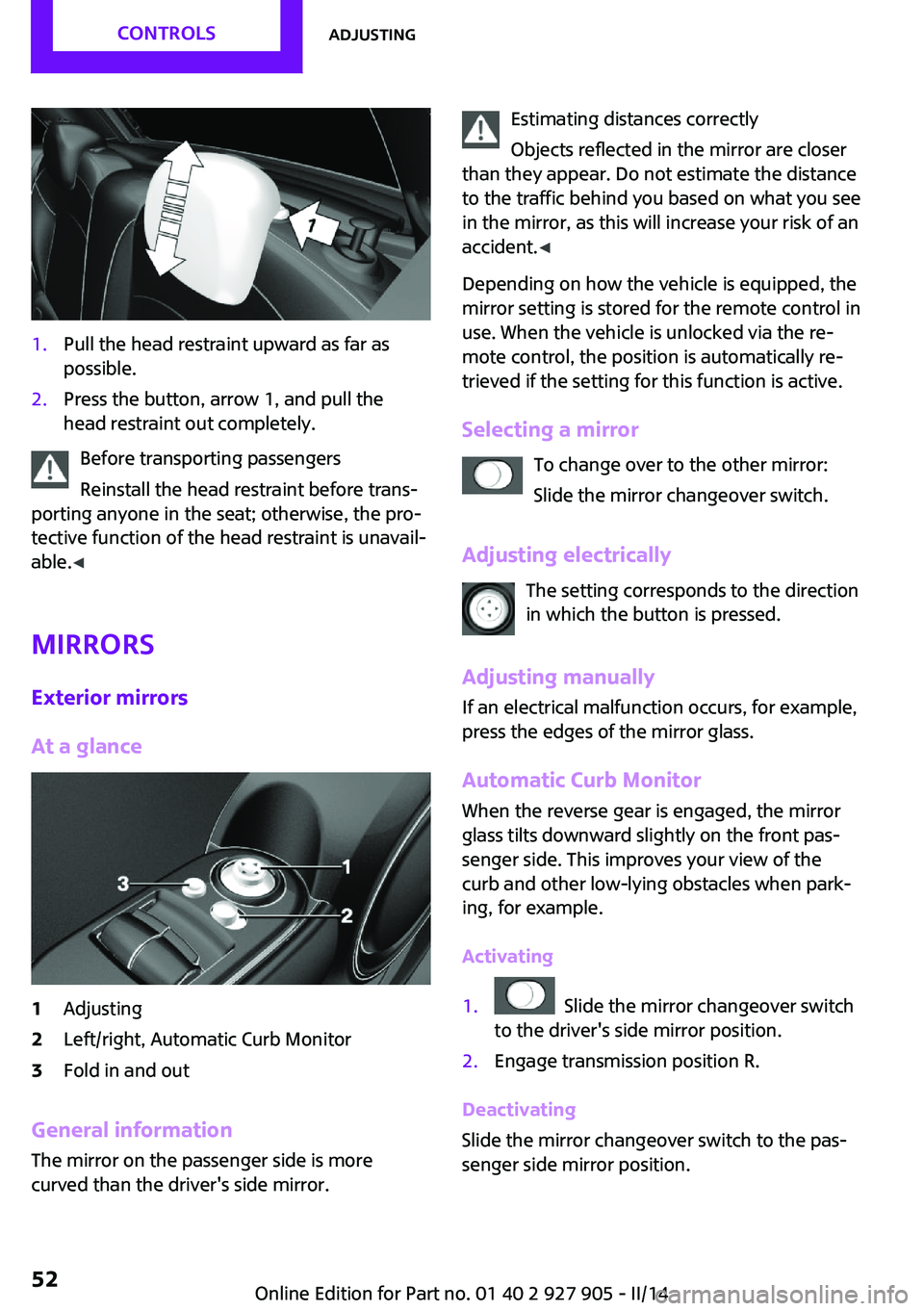
1.Pull the head restraint upward as far as
possible.2.Press the button, arrow 1, and pull the
head restraint out completely.
Before transporting passengers
Reinstall the head restraint before trans‐
porting anyone in the seat; otherwise, the pro‐
tective function of the head restraint is unavail‐
able. ◀
Mirrors Exterior mirrors
At a glance
1Adjusting2Left/right, Automatic Curb Monitor3Fold in and out
General information
The mirror on the passenger side is more
curved than the driver's side mirror.
Estimating distances correctly
Objects reflected in the mirror are closer
than they appear. Do not estimate the distance
to the traffic behind you based on what you see
in the mirror, as this will increase your risk of an
accident. ◀
Depending on how the vehicle is equipped, the
mirror setting is stored for the remote control in
use. When the vehicle is unlocked via the re‐
mote control, the position is automatically re‐
trieved if the setting for this function is active.
Selecting a mirror To change over to the other mirror:Slide the mirror changeover switch.
Adjusting electrically The setting corresponds to the direction
in which the button is pressed.
Adjusting manually If an electrical malfunction occurs, for example,
press the edges of the mirror glass.
Automatic Curb MonitorWhen the reverse gear is engaged, the mirror
glass tilts downward slightly on the front pas‐
senger side. This improves your view of the
curb and other low-lying obstacles when park‐
ing, for example.
Activating1. Slide the mirror changeover switch
to the driver's side mirror position.2.Engage transmission position R.
Deactivating
Slide the mirror changeover switch to the pas‐
senger side mirror position.
Seite 52CONTROLSAdjusting52
Online Edition for Part no. 01 40 2 927 905 - II/14
Page 53 of 230
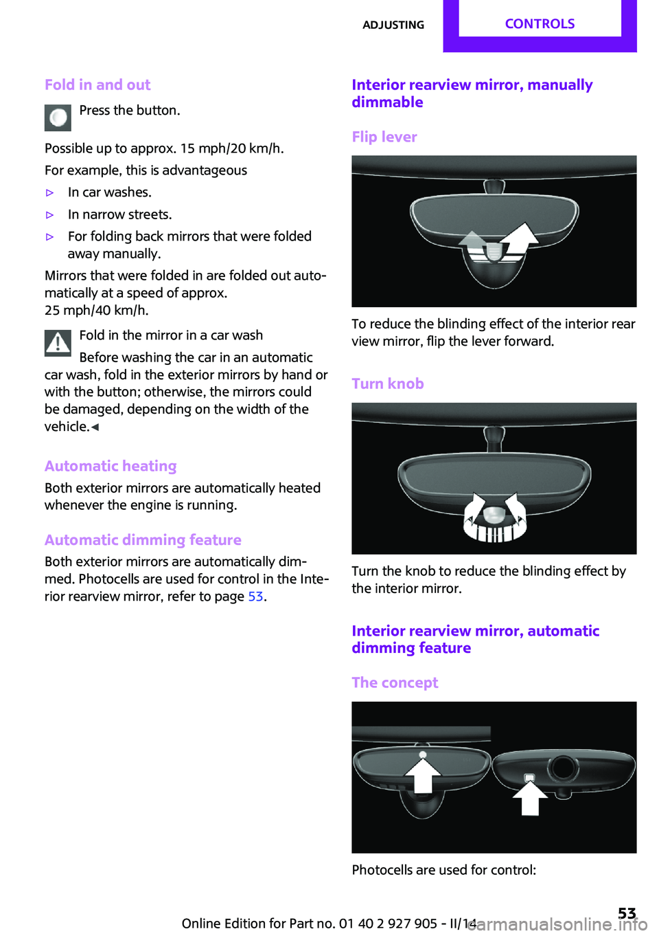
Fold in and outPress the button.
Possible up to approx. 15 mph/20 km/h.
For example, this is advantageous▷In car washes.▷In narrow streets.▷For folding back mirrors that were folded
away manually.
Mirrors that were folded in are folded out auto‐
matically at a speed of approx.
25 mph/40 km/h.
Fold in the mirror in a car wash
Before washing the car in an automatic
car wash, fold in the exterior mirrors by hand or
with the button; otherwise, the mirrors could
be damaged, depending on the width of the
vehicle. ◀
Automatic heating
Both exterior mirrors are automatically heated
whenever the engine is running.
Automatic dimming featureBoth exterior mirrors are automatically dim‐
med. Photocells are used for control in the Inte‐
rior rearview mirror, refer to page 53.
Interior rearview mirror, manually
dimmable
Flip lever
To reduce the blinding effect of the interior rear
view mirror, flip the lever forward.
Turn knob
Turn the knob to reduce the blinding effect by
the interior mirror.
Interior rearview mirror, automatic
dimming feature
The concept
Photocells are used for control:
Seite 53AdjustingCONTROLS53
Online Edition for Part no. 01 40 2 927 905 - II/14
Page 54 of 230

▷In the mirror glass.▷On the back of the mirror.
Functional requirement
For proper operation:
▷Keep the photocells clean.▷Do not cover the area between the inside
rearview mirror and the windshield.
Steering wheel
Note Do not adjust while driving
Do not adjust the steering wheel while
driving; otherwise, an unexpected movement
could result in an accident. ◀
Adjusting
1.Switch on the ignition.2.Fold the lever down.3.Move the steering wheel to the preferred
height and angle to suit your seating posi‐
tion.4.Fold the lever back.5.Switch off the ignition again if necessary.Seite 54CONTROLSAdjusting54
Online Edition for Part no. 01 40 2 927 905 - II/14
Page 55 of 230
Transporting children safelyVehicle equipment
All standard, country-specific and optional
equipment that is offered in the model series is
described in this chapter. Therefore, equipmentis also described that is not available in a vehi‐
cle, e. g., because of the selected optional
equipment or country variant. This also applies
for safety-related functions and systems.
The right place for children
Note
Children in the vehicle
Do not leave children unattended in the
vehicle; otherwise, they could endanger them‐
selves and other persons, e.g., by opening the
doors. ◀
Children should always be in the rear Accident research shows that the safest place
for children is in the back seat.
Transporting children in the rear
Only transport children younger than
13 years of age or shorter than 5 ft/150 cm in
the rear in child restraint fixing systems pro‐
vided in accordance with the age, weight and
size of the child; otherwise, there is an in‐
creased risk of injury in an accident.
Children 13 years of age or older must wear a
safety belt as soon as a suitable child restraint fixing system can no longer be used, due to
their age, weight and size. ◀
Children on the front passenger seat Should it ever be necessary to use a child re‐
straint fixing system in the front passenger
seat, make sure that the front, knee and side
airbags on the front passenger side are deacti‐
vated. Automatic deactivation of front passen‐
ger airbags, refer to page 93.Note
Deactivated front passenger airbags
If a child restraint fixing system is used in
the front passenger seat, the front passenger
airbags must be deactivated; otherwise, there
is an increased risk of injury to the child when
the airbags are triggered, even with a child re‐ straint fixing system. ◀
Installing child re‐
straint fixing systems
Hints Manufacturer's information for child re‐straint fixing systems
To select, mount and use child restraint fixing
systems, observe the information provided by
the system manufacturer; otherwise, the pro‐
tective effect can be impaired. ◀
Ensuring the stability of the child seat
When installing child restraint fixing sys‐
tems, make sure that the child seat is securely
fastened to the backrest of the seat. The angle
of the backrest may need to be adjusted and,
where necessary, the headrest height may also
need to be adjusted, or if possible removed.
Make sure that all backrests are securely
locked. Otherwise, the stability of the child seat
is limited, and there is an increased risk of in‐Seite 55Transporting children safelyCONTROLS55
Online Edition for Part no. 01 40 2 927 905 - II/14
Page 56 of 230
jury because of unexpected movement of the
rear seat backrest. ◀
On the front passenger seat
Deactivating airbags
After installing a child restraint fixing system in
the front passenger seat, make sure that the
front, knee and side airbags on the front pas‐
senger side are deactivated.
Deactivate the front passenger airbags auto‐
matically, refer to page 93.
Deactivating the front passenger airbags If a child restraint fixing system is used in
the front passenger seat, the front passenger
airbags must be deactivated; otherwise, there
is an increased risk of injury to the child when
the airbags are triggered, even with a child re‐
straint fixing system. ◀
Seat position and height
Before installing a child restraint fixing system,
move the front passenger seat as far back as possible and adjust its height to the highest po‐
sition to obtain the best possible position for
the belt and to offer optimal protection in the event of an accident.
If the upper fixing point of the safety belt is lo‐
cated before the belt guide of the child seat,
move the passenger seat carefully forward until
the best possible belt guide position is reached.Child seat security
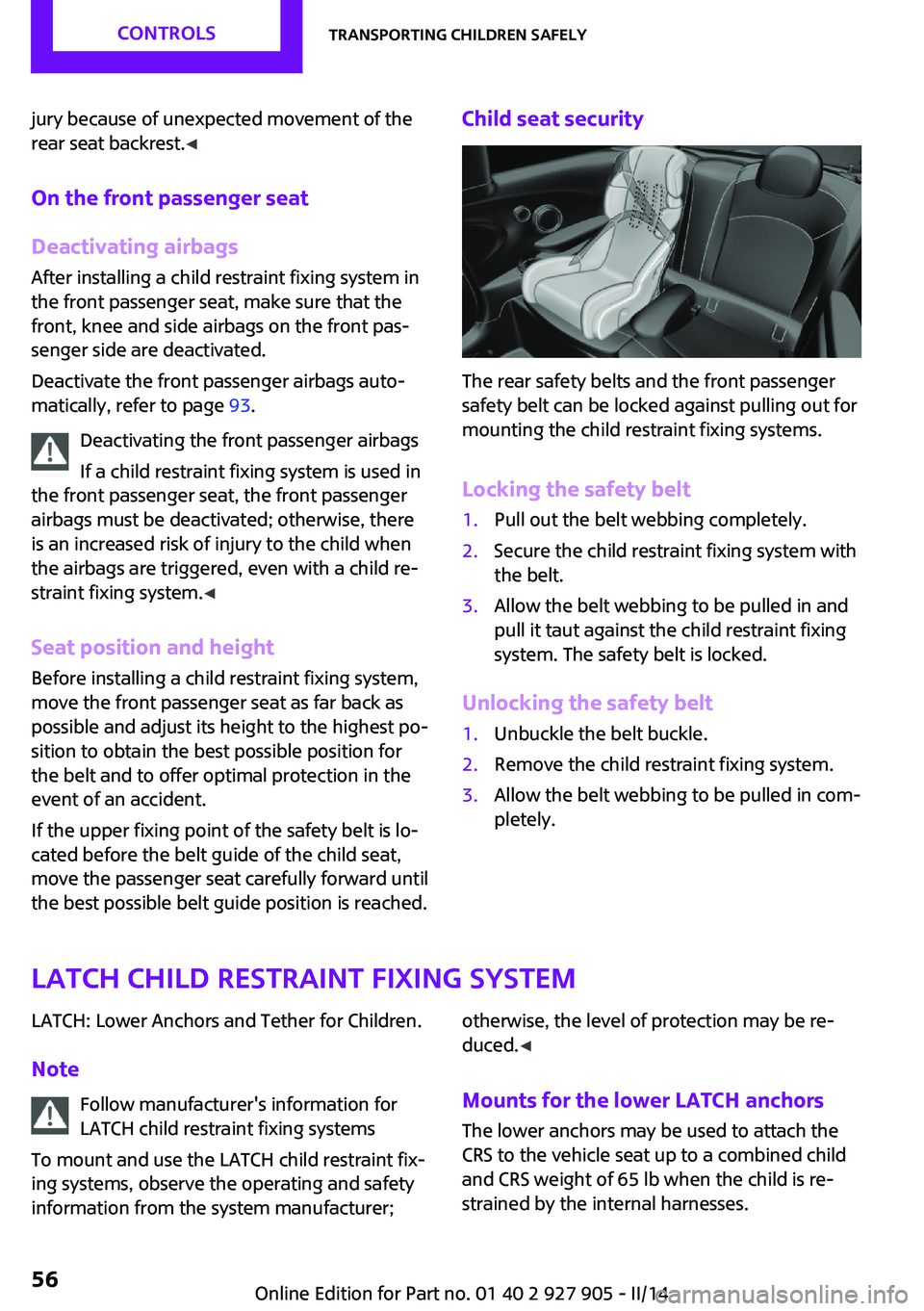
The rear safety belts and the front passenger
safety belt can be locked against pulling out for
mounting the child restraint fixing systems.
Locking the safety belt
1.Pull out the belt webbing completely.2.Secure the child restraint fixing system with
the belt.3.Allow the belt webbing to be pulled in and
pull it taut against the child restraint fixing
system. The safety belt is locked.
Unlocking the safety belt
1.Unbuckle the belt buckle.2.Remove the child restraint fixing system.3.Allow the belt webbing to be pulled in com‐
pletely.
LATCH child restraint fixing system
LATCH: Lower Anchors and Tether for Children.
Note Follow manufacturer's information for
LATCH child restraint fixing systems
To mount and use the LATCH child restraint fix‐
ing systems, observe the operating and safety
information from the system manufacturer;otherwise, the level of protection may be re‐
duced. ◀
Mounts for the lower LATCH anchors
The lower anchors may be used to attach the
CRS to the vehicle seat up to a combined child
and CRS weight of 65 lb when the child is re‐
strained by the internal harnesses.Seite 56CONTROLSTransporting children safely56
Online Edition for Part no. 01 40 2 927 905 - II/14
Page 57 of 230
Correctly engage the lower LATCH an‐
chors
Make sure that the lower LATCH anchors have
properly engaged and that the child restraint
fixing system is resting snugly against the back‐
rest; otherwise, the degree of protection of‐
fered may be reduced. ◀
Before mounting the LATCH child restraint fix‐
ing system, pull the belt away from the child re‐
straint fixing system.
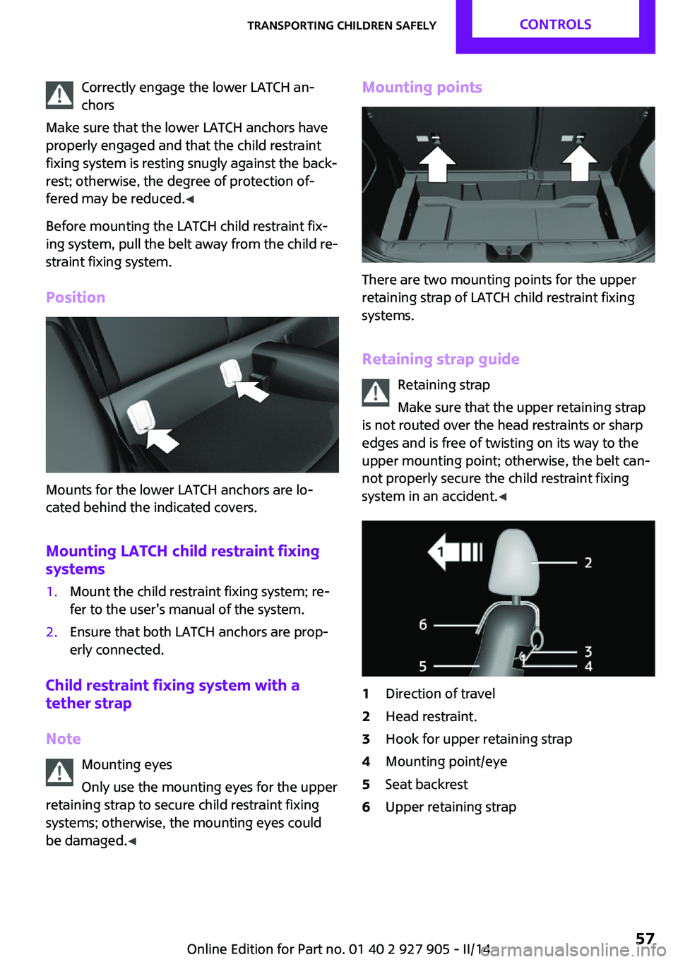
Position
Mounts for the lower LATCH anchors are lo‐
cated behind the indicated covers.
Mounting LATCH child restraint fixing
systems
1.Mount the child restraint fixing system; re‐
fer to the user's manual of the system.2.Ensure that both LATCH anchors are prop‐
erly connected.
Child restraint fixing system with a
tether strap
Note Mounting eyes
Only use the mounting eyes for the upper
retaining strap to secure child restraint fixing
systems; otherwise, the mounting eyes could
be damaged. ◀
Mounting points
There are two mounting points for the upper
retaining strap of LATCH child restraint fixing
systems.
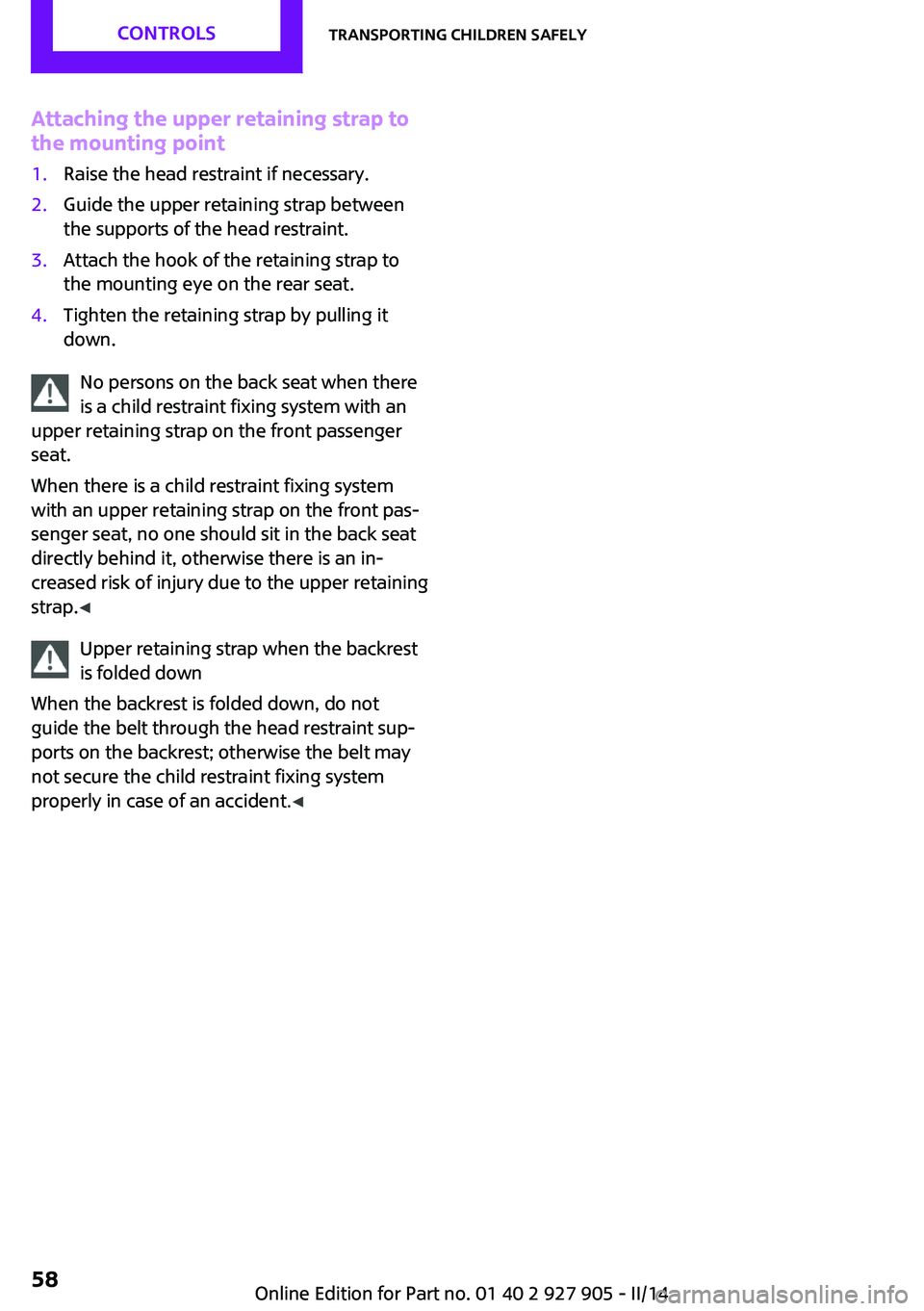
Retaining strap guide Retaining strap
Make sure that the upper retaining strap
is not routed over the head restraints or sharp
edges and is free of twisting on its way to the
upper mounting point; otherwise, the belt can‐
not properly secure the child restraint fixing
system in an accident. ◀
1Direction of travel2Head restraint.3Hook for upper retaining strap4Mounting point/eye5Seat backrest6Upper retaining strapSeite 57Transporting children safelyCONTROLS57
Online Edition for Part no. 01 40 2 927 905 - II/14
Page 58 of 230
Attaching the upper retaining strap to
the mounting point
1.Raise the head restraint if necessary.2.Guide the upper retaining strap between
the supports of the head restraint.
3.Attach the hook of the retaining strap to
the mounting eye on the rear seat.
4.Tighten the retaining strap by pulling it
down.
No persons on the back seat when there
is a child restraint fixing system with an
upper retaining strap on the front passenger
seat.
When there is a child restraint fixing system
with an upper retaining strap on the front pas‐
senger seat, no one should sit in the back seat
directly behind it, otherwise there is an in‐
creased risk of injury due to the upper retaining
strap.◀
Upper retaining strap when the backrest
is folded down
When the backrest is folded down, do not
guide the belt through the head restraint sup‐
ports on the backrest; otherwise the belt may
not secure the child restraint fixing system
properly in case of an accident
Seite 58CONTROLSTransporting children safely58
Online Edition for Part no. 01 40 2 927 905 - II/14
.◀
Page 59 of 230
DrivingVehicle equipmentAll standard, country-specific and optional
equipment that is offered in the model series is
described in this chapter. Therefore, equipment
is also described that is not available in a vehi‐
cle, e. g., because of the selected optional
equipment or country variant. This also applies
for safety-related functions and systems.
Start/Stop button
The concept Pressing the Start/Stop button
switches the ignition on or off
and starts the engine.
Automatic transmission: the en‐
gine starts in selector lever posi‐
tion P or N if the brake pedal is pressed when
you press the Start/Stop button.
Manual transmission: the engine starts if the
clutch pedal is depressed when the Start/Stop
button is pressed.
Ignition on Automatic transmission: press the Start/Stop
button, and do not press on the brake pedal at
the same time.
Manual-shift transmission: press the Start/Stop
button, and do not press on the clutch pedal at
the same time.
All vehicle systems are ready for operation.
Most of the indicator and warning lamps in the
instrument cluster light up for varying lengths
of time.
To save battery power when the engine is off,
switch off the ignition and any unnecessary
electronic systems/power consumers.Note
If the engine is switched off and the ignition is
switched on, the system automatically switches
to the radio ready state when the door is
opened if the lights are switched off or the day‐
time running lights are switched on.
Ignition off
Manual-shift transmission: press the Start/Stop
button again, and do not press on the clutch
pedal at the same time.
Automatic transmission: press the Start/Stop
button again, and do not press on the brake
pedal at the same time.
All indicator lamps in the instrument cluster go
out.
To save battery power when the engine is off,
switch off the ignition and any unnecessary
electronic systems/power consumers.
Ignition automatically cuts off while the vehicle
is stationary and the engine is stopped:▷During locking, also with the low beams ac‐
tivated.▷Shortly before the battery is discharged
completely, so that the engine can still be
started. This function is only available when
the low beams are switched off.▷When opening and closing the driver door,
if the driver's seat belt is unbuckled and the
low beams are switched off.▷While the driver's seat belt is unbuckled, if
the driver's door is open and the low beams
are switched off.
When the ignition is switched off, by opening or
closing the driver's door or unbuckling the driv‐
er's seat belt, the radio ready state remains ac‐
tive.
Seite 59DrivingCONTROLS59
Online Edition for Part no. 01 40 2 927 905 - II/14
Page 60 of 230
Radio ready state
Activate radio ready state:▷When the engine is running: press the Start/
Stop button.
Some electronic systems/power consumers re‐
main ready for operation.
Radio ready state switches off automatically:
▷After approx. 8 minutes.▷When the vehicle is locked using the central
locking system.▷Shortly before the battery is discharged
completely, so that the engine can still be
started.
Starting the engine
General information Enclosed areas
Do not let the engine run in enclosed
areas, since breathing in exhaust fumes may
lead to loss of consciousness and death. The
exhaust gases contain carbon monoxide, an
odorless and colorless, but highly toxic gas. ◀
Unattended vehicle
Do not leave the vehicle unattended with
the engine running; doing so poses a risk of
danger.
Before leaving the vehicle with the engine run‐
ning, set the parking brake and place the trans‐
mission in selector lever position P or neutral to
prevent the vehicle from moving. ◀
Repeated starting in quick succession
Avoid repeated unsuccessful attempts to
start the vehicle or starting the vehicle several
times in quick succession. Otherwise, the fuel is
not burned or is inadequately burned, posing a
risk of overheating and damage to the catalytic
converter. ◀
Do not wait for the engine to warm-up while
the vehicle remains stationary. Start driving at
moderate engine speeds.
Diesel engine If the engine is cold and temperatures are be‐
low approx. 32 ℉/0 ℃, the start process may
be delayed somewhat due to automatic pre‐
heating.
A Check Control message is displayed.
Automatic transmission
Starting the engine1.Depress the brake pedal.2.Engage selector lever position P or N.3.Press the Start/Stop button.
The ignition is activated automatically for a cer‐
tain time and is stopped as soon as the engine
starts.
Manual transmission
Starting the engine
1.Depress the brake pedal.2.Press on the clutch pedal and shift to neu‐
tral.3.Press the Start/Stop button.
The ignition is activated automatically for a cer‐
tain time and is stopped as soon as the engine
starts.
Engine stop
General information Take the remote control with you
Take the remote control with you when
leaving the vehicle so that children, for exam‐
ple, cannot start the engine. ◀
Seite 60CONTROLSDriving60
Online Edition for Part no. 01 40 2 927 905 - II/14