turn signal MINI COOPER 2015 User Guide
[x] Cancel search | Manufacturer: MINI, Model Year: 2015, Model line: COOPER, Model: MINI COOPER 2015Pages: 248, PDF Size: 5.43 MB
Page 114 of 248

Overview
Button in the vehicle
Intelligent Safety button
Camera
The camera is installed near the interior rear‐
view mirror.
Keep the windshield in the area behind the in‐
terior rearview mirror clean and clear.
Switching on/off
Switching on automatically
The system is automatically active after every
driving-off.
Switching on/off manually Press button briefly:
▷The menu for the intelligent safety
system is displayed. The systems
are individually switched off ac‐
cording to their respective settings.▷LED lights up orange or goes out respective
to their individual settings.
Adjust as needed. Individual settings are stored
for the profile currently used.
Press button again:
▷All Intelligent Safety systems are
activated.▷The LED lights up green.
Hold down button:
▷All Intelligent Safety systems are
turned off.▷The LED goes out.
Warning with braking function
Display
If a collision with a person detected in this way
is imminent, a warning symbol appears on the
instrument cluster and in the Head-up Display.
The red symbol is displayed and a signal
sounds.
Intervene immediately by braking or
make an evasive maneuver.
Braking intervention
The warning prompts the driver himself/herself
to react. During a warning, the maximum brak‐ ing force is used. Premise for the brake booster
is sufficiently quick and sufficiently hard step‐
ping on the brake pedal. The system can assist
with some braking intervention if there is risk of
a collision. At low speeds vehicles may thus come to a complete stop.
Manual transmission: During a braking inter‐
vention up to a complete stop, the engine may
be shut down.
The braking intervention is executed only if DSC Dynamic Stability Control is switched on.
Seite 114CONTROLSSafety114
Online Edition for Part no. 01 40 2 964 625 - X/15
Page 130 of 248
3."Volume settings"4."PDC"5.To adjust: turn the Controller.6.To store: press the Controller.
Settings are stored for the profile currently
used.
Visual warning The approach of the vehicle to an object can be
shown on the Control Display. Objects that are
farther away are already displayed on the Con‐
trol Display before a signal sounds.
A display appears as soon as Park Distance
Control (PDC) is activated.
The range of the sensors is represented in col‐
ors: red, green and yellow.
When the image of the rearview camera is dis‐
played, the switch can be made to PDC:
"Rear view camera"
System limits
Information WARNING
The system can react incorrectly or not at
all due to the system limits. There is risk of acci‐
dents or risk of property damage. Observe the
system limits and actively interfere if needed. ◀
Limits of ultrasonic measurement
Ultrasonic measuring might not function under
the following circumstances:
▷For small children and animals.▷For persons with certain clothing, for exam‐
ple coats.▷With external interference of the ultra‐
sound, for example from passing vehicles
or loud machines.▷When sensors are dirty, iced over, damaged
or out of position.▷If cargo protrudes.▷Under certain weather conditions such as
high relative humidity, rain, snowfall, ex‐
treme heat or strong wind.▷With tow bars and trailer couplings of other
vehicles.▷With thin or wedge-shaped objects.▷With moving objects.▷With elevated, protruding objects such as
ledges or cargo.▷With objects with corners and sharp edges.▷With objects with a fine surface structure
such as fences.▷For objects with porous surfaces.
Low objects already displayed, for example,
curbs, can move into the blind area of the sen‐
sors before or after a continuous tone sounds.
False warnings PDC may issue a warning under the following
conditions even though there is no obstacle
within the detection range:
▷In heavy rain.▷When sensors are very dirty or covered with
ice.▷When sensors are covered in snow.▷On rough road surfaces.▷On uneven surfaces, such as speed bumps.▷In large buildings with right angles and
smooth walls, for example, in underground
garages.▷In automatic car washes.▷Through heavy pollution.▷Due to other ultrasound sources, for exam‐
ple, sweeping machines, high pressure
steam cleaners or neon lights.
The malfunction is signaled by a continuous
tone alternating between the front and rear
speakers. As soon as the malfunction due
to other ultrasound sources is no longer
present, the system is again fully functional.Seite 130CONTROLSDriving comfort130
Online Edition for Part no. 01 40 2 964 625 - X/15
Page 135 of 248
▷When parking in parking spaces on the
driver's side, the corresponding turn signal
must be set.
Switching on and activating
Switching on with the button Press button.
The LED lights up.
The current status of the parking space search
is indicated on the Control Display.
Parking assistant is activated automatically.
Switching on with reverse gear
Shift into reverse.
The current status of the parking space search
is indicated on the Control Display.
To activate:
"Parking Assistant"
Indicator on the Control Display
System activated/deactivated
SymbolMeaning Gray: the system is not available.
White: the system is available but not
activated. The system is activated.
Parking space search and system status
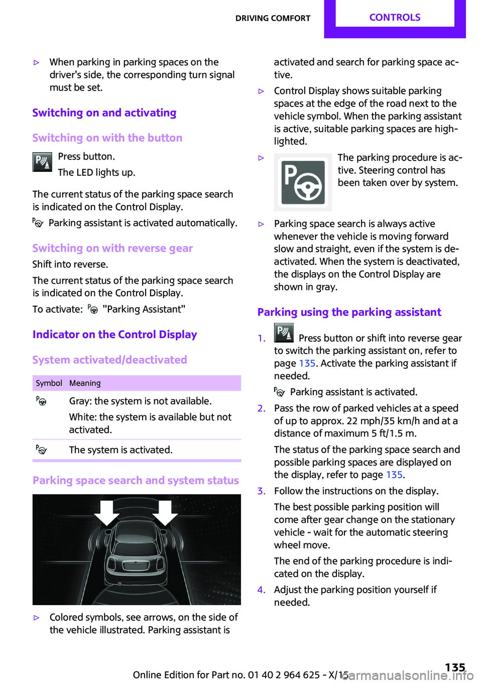
▷Colored symbols, see arrows, on the side of
the vehicle illustrated. Parking assistant isactivated and search for parking space ac‐
tive.▷Control Display shows suitable parking
spaces at the edge of the road next to the
vehicle symbol. When the parking assistant
is active, suitable parking spaces are high‐
lighted.▷The parking procedure is ac‐
tive. Steering control has
been taken over by system.▷Parking space search is always active
whenever the vehicle is moving forward
slow and straight, even if the system is de‐
activated. When the system is deactivated,
the displays on the Control Display are
shown in gray.
Parking using the parking assistant
1. Press button or shift into reverse gear
to switch the parking assistant on, refer to
page 135. Activate the parking assistant if
needed.
Parking assistant is activated.
2.Pass the row of parked vehicles at a speed
of up to approx. 22 mph/35 km/h and at a
distance of maximum 5 ft/1.5 m.
The status of the parking space search and
possible parking spaces are displayed on
the display, refer to page 135.3.Follow the instructions on the display.
The best possible parking position will
come after gear change on the stationary
vehicle - wait for the automatic steering
wheel move.
The end of the parking procedure is indi‐
cated on the display.4.Adjust the parking position yourself if
needed.Seite 135Driving comfortCONTROLS135
Online Edition for Part no. 01 40 2 964 625 - X/15
Page 147 of 248

4.Likewise, press and hold the button of the
desired function on the hand-held trans‐
mitter.5.Release both buttons as soon as the interior
rearview mirror LED flashes more rapidly.
The LED flashing faster indicates that the
button on the interior rearview mirror has
been programmed. The system can then be
controlled by the button on the interior
rearview mirror.
If the LED does not flash faster after at least
60 seconds, change the distance and re‐
peat the step. Several more attempts at dif‐
ferent distances may be necessary. Wait at
least 15 seconds between attempts.
Canada: if programming with the hand-
held transmitter was interrupted, hold
down the interior rearview mirror button
and repeatedly press and release the hand-
held transmitter button for 2 seconds.
Controls
WARNING
Body parts can be jammed when operat‐
ing remote-controlled systems, for example the
garage door, using the integrated universal re‐
mote control. There is risk of injuries or risk of
property damage. Make sure that the area of
movement of the respective system is clear
during programming and operation. Also follow
the safety instructions of the hand-held trans‐
mitter. ◀
The system, such as the garage door, can be
operated using the button on the interior rear‐
view mirror while the engine is running or
when the ignition is started. To do this, hold
down the button within receiving range of the
system until the function is activated. The inte‐
rior rearview mirror LED stays lit while the wire‐
less signal is being transmitted.
Deleting stored functions
Press and hold the left and right button on the
interior rearview mirror simultaneously for ap‐
proximately 20 seconds until the LED flashes
rapidly. All stored functions will be deleted. The
functions cannot be deleted individually.
Digital compass
Overview1Control button2Mirror display
Mirror display The point of the compass is displayed in the
mirror when driving straight.
Operating concept Various functions can be called up by pressing
the control button with a pointed object, such
as the tip of a ballpoint pen or similar object.
The following setting options are displayed in
succession, depending on how long the control
button is pressed:
▷Pressed briefly: turns display on/off.▷3 to 6 seconds: compass zone setting.▷6 to 9 seconds: compass calibration.▷9 to 12 seconds: left/right-hand steering
setting.▷12 to 15 seconds: language setting.
Setting the compass zones
Sets the particular compass zones on the vehi‐
cle so that the compass operates correctly; re‐
fer to World map with compass zones.
Seite 147Interior equipmentCONTROLS147
Online Edition for Part no. 01 40 2 964 625 - X/15
Page 165 of 248
Roof racks are available as special accessories.Securing
Follow the installation instructions of the roof
rack.
Loading
Because roof racks raise the vehicle's center of
gravity when loaded, they have a major effect
on vehicle handling and steering response.
Therefore, note the following when loading and
driving:▷Do not exceed the approved roof/axle
loads and the approved gross vehicle
weight.▷Be sure that adequate clearance is main‐
tained for tilting and opening the glass sun‐
roof.▷Distribute the roof load uniformly.▷The roof load should not extend past the
loading area.▷Always place the heaviest pieces on the
bottom.▷Secure the roof luggage firmly, e.g., tie with
ratchet straps.▷Do not let objects project into the opening
path of the tailgate.▷Drive cautiously and avoid sudden acceler‐
ation and braking maneuvers. Take corners
gently.
Rear luggage rack
General information Installation only possible with rear luggage rack
preparation.
Rear racks are available as special accessories.
Information Follow the installation instructions of the rear
luggage rack.
Drive cautiously and avoid sudden acceleration
and braking maneuvers. Take corners gently.
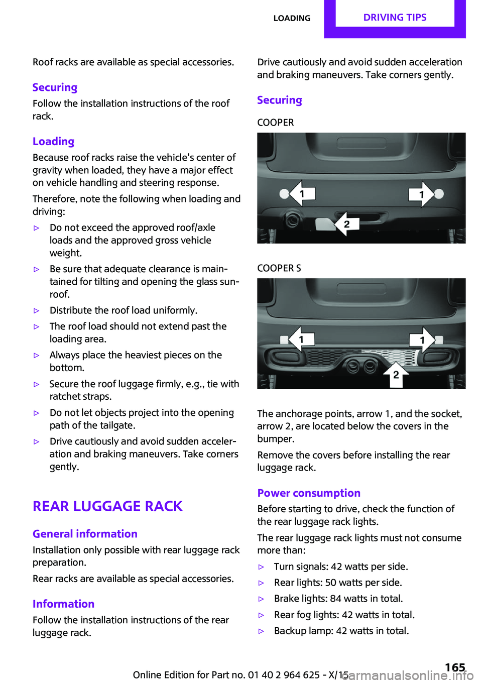
SecuringCOOPERCOOPER S
The anchorage points, arrow 1, and the socket,
arrow 2, are located below the covers in the
bumper.
Remove the covers before installing the rear
luggage rack.
Power consumption
Before starting to drive, check the function of
the rear luggage rack lights.
The rear luggage rack lights must not consume
more than:
▷Turn signals: 42 watts per side.▷Rear lights: 50 watts per side.▷Brake lights: 84 watts in total.▷Rear fog lights: 42 watts in total.▷Backup lamp: 42 watts in total.Seite 165LoadingDRIVING TIPS165
Online Edition for Part no. 01 40 2 964 625 - X/15
Page 206 of 248

Front lights, bulb replacement
Overview
Halogen headlights1Low beams/high beams2Turn signal
LED headlights
1Daytime running lights2Low beams/high beams3Turn signalBug light1Parking lights2Daytime running lights3Fog lights
LED bug light
1Parking lights2Fog lights
LED low beams/LED high beams Follow the general instructions on lights and
bulbs, refer to page 205.
The lights feature LED technology. In the case
of a malfunction, contact a dealer’s service cen‐
ter or another qualified service center or repair
shop.
Halogen low beams/halogen high
beams
Follow the general instructions on lights and
bulbs, refer to page 205.
Seite 206MOBILITYReplacing components206
Online Edition for Part no. 01 40 2 964 625 - X/15
Page 207 of 248
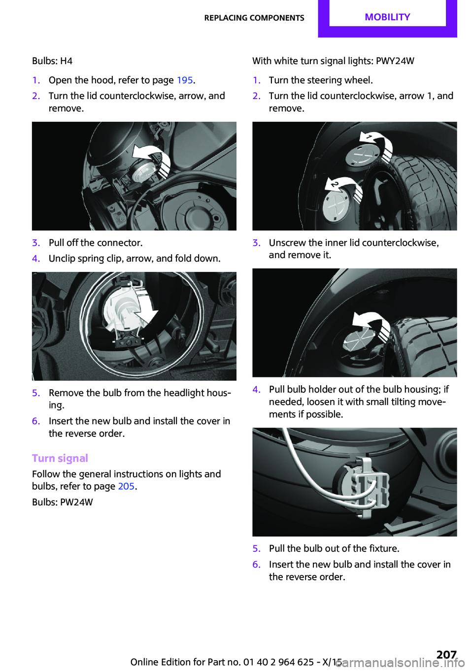
Bulbs: H41.Open the hood, refer to page 195.2.Turn the lid counterclockwise, arrow, and
remove.3.Pull off the connector.4.Unclip spring clip, arrow, and fold down.5.Remove the bulb from the headlight hous‐
ing.6.Insert the new bulb and install the cover in
the reverse order.
Turn signal
Follow the general instructions on lights and
bulbs, refer to page 205.
Bulbs: PW24W
With white turn signal lights: PWY24W1.Turn the steering wheel.2.Turn the lid counterclockwise, arrow 1, and
remove.3.Unscrew the inner lid counterclockwise,
and remove it.4.Pull bulb holder out of the bulb housing; if
needed, loosen it with small tilting move‐
ments if possible.5.Pull the bulb out of the fixture.6.Insert the new bulb and install the cover in
the reverse order.Seite 207Replacing componentsMOBILITY207
Online Edition for Part no. 01 40 2 964 625 - X/15
Page 209 of 248
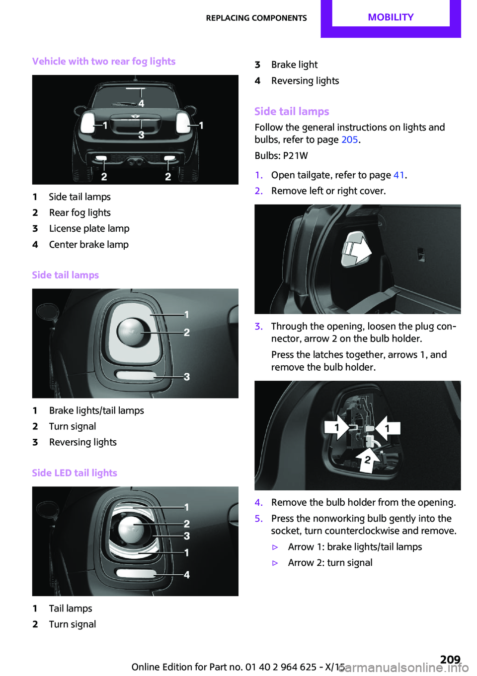
Vehicle with two rear fog lights1Side tail lamps2Rear fog lights3License plate lamp4Center brake lamp
Side tail lamps
1Brake lights/tail lamps2Turn signal3Reversing lights
Side LED tail lights
1Tail lamps2Turn signal3Brake light4Reversing lights
Side tail lampsFollow the general instructions on lights and
bulbs, refer to page 205.
Bulbs: P21W
1.Open tailgate, refer to page 41.2.Remove left or right cover.3.Through the opening, loosen the plug con‐
nector, arrow 2 on the bulb holder.
Press the latches together, arrows 1, and
remove the bulb holder.4.Remove the bulb holder from the opening.5.Press the nonworking bulb gently into the
socket, turn counterclockwise and remove.▷Arrow 1: brake lights/tail lamps▷Arrow 2: turn signalSeite 209Replacing componentsMOBILITY209
Online Edition for Part no. 01 40 2 964 625 - X/15
Page 211 of 248
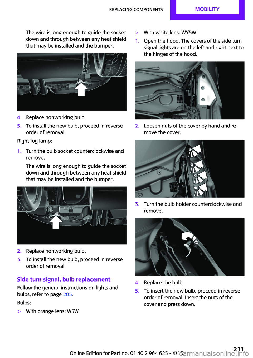
The wire is long enough to guide the socket
down and through between any heat shield
that may be installed and the bumper.4.Replace nonworking bulb.5.To install the new bulb, proceed in reverse
order of removal.
Right fog lamp:
1.Turn the bulb socket counterclockwise and
remove.
The wire is long enough to guide the socket
down and through between any heat shield
that may be installed and the bumper.2.Replace nonworking bulb.3.To install the new bulb, proceed in reverse
order of removal.
Side turn signal, bulb replacement
Follow the general instructions on lights and
bulbs, refer to page 205.
Bulbs:
▷With orange lens: W5W▷With white lens: WY5W1.Open the hood. The covers of the side turn
signal lights are on the left and right next to
the hinges of the hood.2.Loosen nuts of the cover by hand and re‐
move the cover.3.Turn the bulb holder counterclockwise and
remove.4.Replace the bulb.5.To insert the new bulb, proceed in reverse
order of removal. Insert the nuts of the
cover and press down.Seite 211Replacing componentsMOBILITY211
Online Edition for Part no. 01 40 2 964 625 - X/15
Page 218 of 248
3.Let both engines run for several minutes.4.Disconnect the jumper cables in the reverse
order.
Check the battery and recharge if needed.
Tow-starting and towing
Information WARNING
Due to system limits, individual functions
can malfunction during tow-starting/towing
with the Intelligent Safety systems activated,
for example approach control warning with
light braking function. There is risk of an acci‐
dent. Switch all Intelligent Safety systems off
prior to tow-starting/towing. ◀
Switching off Intelligent Safety systems, refer to
page 109.
Steptronic transmission: transporting
the vehicle
Information The vehicle must not be towed if the front
wheels are touching the ground.
CAUTION
The vehicle can be damaged when tow‐
ing the vehicle with a lifted rear axle. There is
risk of property damage. Have vehicle trans‐
ported only with lifted front axle or on a load‐
ing platform. ◀
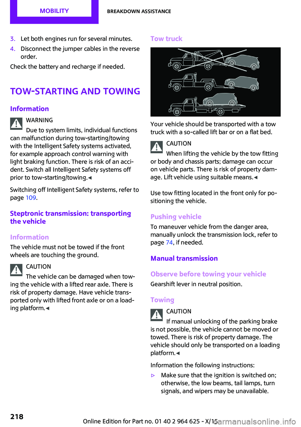
Tow truck
Your vehicle should be transported with a tow
truck with a so-called lift bar or on a flat bed.
CAUTION
When lifting the vehicle by the tow fitting
or body and chassis parts; damage can occur
on vehicle parts. There is risk of property dam‐
age. Lift vehicle using suitable means. ◀
Use tow fitting located in the front only for po‐
sitioning the vehicle.
Pushing vehicle
To maneuver vehicle from the danger area,
manually unlock the transmission lock, refer to
page 74, if needed.
Manual transmission
Observe before towing your vehicle
Gearshift lever in neutral position.
Towing CAUTION
If manual unlocking of the parking brake
is not possible, the vehicle cannot be moved or
towed. There is risk of property damage. The
vehicle should only be transported on a loading
platform. ◀
Information the following instructions:
▷Make sure that the ignition is switched on;
otherwise, the low beams, tail lamps, turn
signals, and wipers may be unavailable.Seite 218MOBILITYBreakdown assistance218
Online Edition for Part no. 01 40 2 964 625 - X/15