MINI COOPER CONVERTIBLE 2007 Owners Manual
Manufacturer: MINI, Model Year: 2007, Model line: COOPER CONVERTIBLE, Model: MINI COOPER CONVERTIBLE 2007Pages: 172, PDF Size: 1.9 MB
Page 131 of 172

129
OVERVIEW REPAIRSOPERATION CONTROLS DATA INDEX
WIPER BLADES LAMPS AND BULBSRear window wiper*1. Rotate the wiper arm completely out
2. Turn the wiper blade as far as it will go
to the rear
3. Press the wiper blade against the limit
and thus out of the mounting
4. Press the new wiper blade into the
mounting.
Lamps and bulbs are an important compo-
nent of vehicle safety. Therefore, proceed
carefully when handling bulbs.
To replace bulbs which are not described
here, please contact a MINI Dealer or a
workshop that has specially trained per-
sonnel working in accordance with the
specifications of the MINI manufacturer.
Do not touch the glass portion of a
new bulb with your bare hands since
even small amounts of impurities burn into
the surface and reduce the service life of
the bulb. Use a clean cloth, paper napkin, or
similar material, or hold the bulb by its
metallic base.<
A replacement bulb set can be obtained at
your MINI Dealer.
Whenever working on the electrical
system, switch off the electrical
accessory you are working on or disconnect
the cable from the negative terminal of the
battery. Failure to do this could result in
short circuits.
To prevent injuries and damage, comply
with any instructions provided by the bulb
manufacturer.<
Page 132 of 172

130
LAMPS AND BULBS1 Low beamsH7 bulb, 55 watts2High beams H7 bulb, 55 watts
The H7 bulb is pressurized. Therefore,
wear safety glasses and protective
gloves. If the lamp is damaged there is a
risk of injury.<
For checking and adjusting headlamp
aim, please contact your MINI
Dealer.
1. Gently pull the retaining wire of the
headlamp cover and guide it outwards
2. Fold down the headlamp cover
3. Disconnect the cable connector from the
bulb socket and pull out the bulb
4. Place the bulb holder on the lower edge
of the mounting and press it in until it
engages in the bulb socket
5. Reconnect the cable connector and
install the headlamp cover again.Xenon lamps*The service life of these bulbs is very long
and the probability of a failure is very low,
provided that they are not switched on and
off an unusual number of times. If one of
these bulbs should nevertheless fail, it is
possible to continue driving with great cau-
tion using the fog lamps, provided traffic
laws in your area do not prohibit this.
Have any work on the xenon lamp
system, including bulb replacement,
carried out only by a MINI Dealer or a work-
shop that has specially trained personnel
working in accordance with the specifica-
tions of the MINI manufacturer. Due to
high voltage, there is a risk of fatal injury if
work on the xenon lamps is carried out
improperly.<
Turn signal indicators, front 21 watt bulb
1. Open the bonnet
2. Reach into the opening for the turn sig-
nal indicators from above
3. Apply gentle pressure to the bulb holder
while turning it to the left
4. Remove and replace the bulb.Parking lamps and standing lamps5watt bulb
The parking lamps and standing lamps are
integrated in the lamp housing of the turn
signal indicator.
1. Turn the bulb holder to the left and pull
out
2. Remove and replace the bulb.
Page 133 of 172

131
OVERVIEW REPAIRSOPERATION CONTROLS DATA INDEX
LAMPS AND BULBSSide turn signal indicators5watt bulb
1. Slide the lamp toward the rear of the
vehicle and remove
2. Remove and replace the bulb.
Tail lampsTurn signal lamp 1: 21 watts
Rear lamp 2: 21/5 watt bulb
Backup lamp 3: 16 watts
1 Turn signal indicator yellow
2 Rear lamp/Brake lamp red
3 Backup lamp white
Replacing bulbsTo access the bulb holder, remove the cover
on the side panel in the luggage compart-
ment for MINI and MINI Convertible.
1. Unplug the power supply, arrow 1
2. Squeeze the retaining clips together, see
arrows 2, and remove the bulb holder
3. Apply gentle pressure to the bulb while
turning it to the left
4. Remove and replace the bulb
5. Press the bulb holder into position until
you hear it engage
6. Plug in the power supply.
Page 134 of 172

132
LAMPS AND BULBSRear fog lamp*With the space-saver spare tire option:
Access to the lamp via the back or under-
side of the bumper.
1. Press the clips together
2. Push the lamp out of the bumper
3. Apply gentle pressure to the bulb while
turning it to the left
4. Remove and replace the bulb.
Other equipment:
In the event of a malfunction, please
contact your MINI Dealer or a work-
shop that has specially trained personnel
working in accordance with the specifica-
tions of your MINI manufacturer.<
License plate lamps 5watt bulb
As an example, the illustration shows the
license plate lamp of the MINI.
1. Apply a screwdriver to the recess and
lever out the lamp cover
2. Replace the bulb.Light-emitting diodes (LEDs)Light-emitting diodes installed behind
translucent lenses serve as the light
sources for many of the controls and dis-
plays in your vehicle. These light-emitting
diodes are related to conventional lasers,
and legislation defines them as light-emit-
ting diodes, Class 1.
Do not remove the protective lenses
and avoid staring directly at the unfil-
tered beam for several hours, as inflamma-
tion of the retina could result.<
Page 135 of 172

133
OVERVIEW REPAIRSOPERATION CONTROLS DATA INDEX
REPAIRING A FLAT TIRE SPACE-SAVER SPARE TIRE
*
Safety measures in the event of a
flat:
Park the vehicle as far away from flowing
traffic as possible, and switch on the haz-
ard warning flashers.
Turn the steering wheel to the straight-
ahead wheel position and engage the
steering lock. Engage the parking brake and
shift into 1st or reverse gear – selector lever
in P.
All passengers should be outside the vehi-
cle and well away from your immediate
working area – behind a guardrail, for
instance.
If a portable hazard warning lamp is avail-
able, set it up on the roadside at an appro-
priate distance from the rear of the vehicle.
Comply with all safety guidelines and regu-
lations.<
In the event of a flat tire, different proce-
dures should be followed depending on the
equipment included in your vehicle:
>Vehicles with Run-Flat Tires, refer to
page111
>Vehicles with a space-saver spare tire,
refer to the following section
>Vehicles with MINI Mobility System,
refer to page137.
To change a space-saver spare tire, proceed
as follows:
>Remove space-saver spare tire, refer to
the section after the next one
>Prepare for tire change, refer to page135
>Jack up the vehicle, refer to page136
>Mount the space-saver spare tire, refer
to page136
>Tighten the lug bolts, refer to page136
>Drive with space-saver spare tire, refer to
page135.
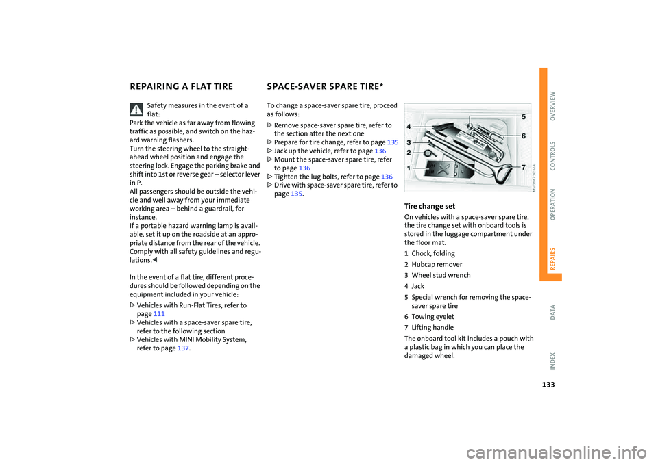
Tire change setOn vehicles with a space-saver spare tire,
the tire change set with onboard tools is
stored in the luggage compartment under
the floor mat.
1 Chock, folding
2 Hubcap remover
3 Wheel stud wrench
4Jack
5 Special wrench for removing the space-
saver spare tire
6 Towing eyelet
7 Lifting handle
The onboard tool kit includes a pouch with
a plastic bag in which you can place the
damaged wheel.
Page 136 of 172

134
SPACE-SAVER SPARE TIRE
*
Removing the space-saver spare tire
The screw connection of the space-saver
spare tire is in the luggage compartment
under the floor mat, on the base of the
storage compartment for the tire change
set.
1. Loosen the screw connection using the
special wrench
2. Take out the cover panel
3. Screw the lifting handle from the
onboard tool kit onto the thread
4. Raise the lifting handle slightly
5. Squeeze the securing spring
6. The space-saver spare tire is released
and must be held by the lifting handle
7. Lower the space-saver spare tire with
the lifting handle
8. Unscrew the lifting handle
Page 137 of 172

135
OVERVIEW REPAIRSOPERATION CONTROLS DATA INDEX
SPACE-SAVER SPARE TIRE
*
CHANGING TIRES
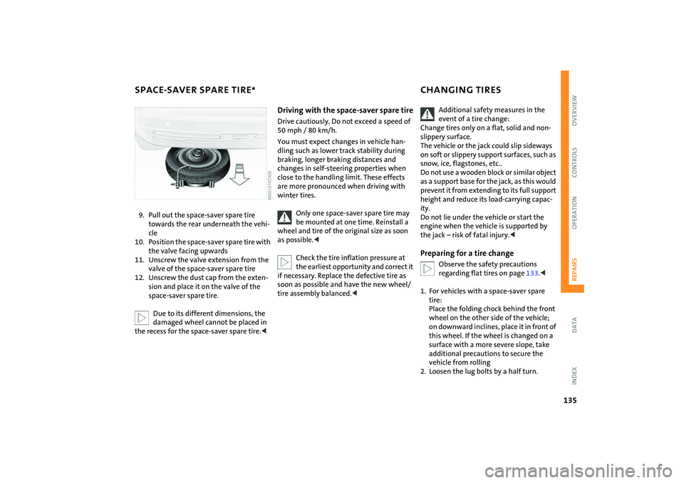
9. Pull out the space-saver spare tire
towards the rear underneath the vehi-
cle
10. Position the space-saver spare tire with
the valve facing upwards
11. Unscrew the valve extension from the
valve of the space-saver spare tire
12. Unscrew the dust cap from the exten-
sion and place it on the valve of the
space-saver spare tire.
Due to its different dimensions, the
damaged wheel cannot be placed in
the recess for the space-saver spare tire.<
Driving with the space-saver spare tireDrive cautiously. Do not exceed a speed of
50 mph / 80 km/h.
You must expect changes in vehicle han-
dling such as lower track stability during
braking, longer braking distances and
changes in self-steering properties when
close to the handling limit. These effects
are more pronounced when driving with
winter tires.
Only one space-saver spare tire may
be mounted at one time. Reinstall a
wheel and tire of the original size as soon
as possible.<
Check the tire inflation pressure at
the earliest opportunity and correct it
if necessary. Replace the defective tire as
soon as possible and have the new wheel/
tire assembly balanced.<
Additional safety measures in the
event of a tire change:
Change tires only on a flat, solid and non-
slippery surface.
The vehicle or the jack could slip sideways
on soft or slippery support surfaces, such as
snow, ice, flagstones, etc..
Do not use a wooden block or similar object
as a support base for the jack, as this would
prevent it from extending to its full support
height and reduce its load-carrying capac-
ity.
Do not lie under the vehicle or start the
engine when the vehicle is supported by
the jack – risk of fatal injury.<
Preparing for a tire change
Observe the safety precautions
regarding flat tires on page133.<
1. For vehicles with a space-saver spare
tire:
Place the folding chock behind the front
wheel on the other side of the vehicle;
on downward inclines, place it in front of
this wheel. If the wheel is changed on a
surface with a more severe slope, take
additional precautions to secure the
vehicle from rolling
2. Loosen the lug bolts by a half turn.
Page 138 of 172

136
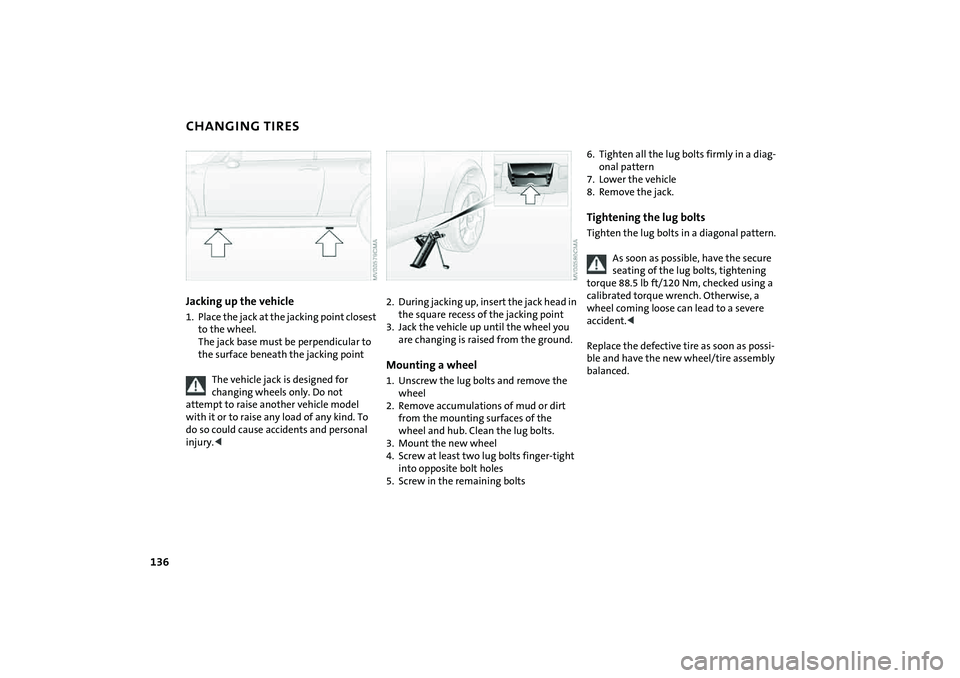
CHANGING TIRESJacking up the vehicle1. Place the jack at the jacking point closest
to the wheel.
The jack base must be perpendicular to
the surface beneath the jacking point
The vehicle jack is designed for
changing wheels only. Do not
attempt to raise another vehicle model
with it or to raise any load of any kind. To
do so could cause accidents and personal
injury.<
2. During jacking up, insert the jack head in
the square recess of the jacking point
3. Jack the vehicle up until the wheel you
are changing is raised from the ground.Mounting a wheel1. Unscrew the lug bolts and remove the
wheel
2. Remove accumulations of mud or dirt
from the mounting surfaces of the
wheel and hub. Clean the lug bolts.
3. Mount the new wheel
4. Screw at least two lug bolts finger-tight
into opposite bolt holes
5. Screw in the remaining bolts
6. Tighten all the lug bolts firmly in a diag-
onal pattern
7. Lower the vehicle
8. Remove the jack.Tightening the lug boltsTighten the lug bolts in a diagonal pattern.
As soon as possible, have the secure
seating of the lug bolts, tightening
torque 88.5 lb ft/120 Nm, checked using a
calibrated torque wrench. Otherwise, a
wheel coming loose can lead to a severe
accident.<
Replace the defective tire as soon as possi-
ble and have the new wheel/tire assembly
balanced.
Page 139 of 172

137
OVERVIEW REPAIRSOPERATION CONTROLS DATA INDEX
MINI MOBILITY SYSTEM
*
MINI Mobility System
The MINI Mobility System is provided to
help you repair a flat tire. With the help of
this system you can apply a liquid sealant
on the inside of the tire, which seals the
damaged area and enables you to continue
to drive.Preparing for tire repair
Before using the MINI Mobility Sys-
tem read the warning and danger
precautions on the equipment.<
If possible, leave objects in which have
been forced into the tire.
Take off the tag regarding speed limits and
stick it onto the steering wheel.
Using the MINI Mobility SystemIn order to repair a flat tire with the MINI
Mobility System, proceed as follows:
>Pump in liquid sealant, refer to page138
>Reinflate the tire, refer to page138
>Distribute liquid sealant, refer to
page139
>Check tire inflation pressure, refer to
page139
>Drive on, refer to page139.
MINI Mobility System with onboard
tools The MINI Mobility System with tire change
set and onboard tools is located in the lug-
gage compartment under the floor mat:
1Jack
2 Wheel stud wrench
3 Hubcap remover
4 Wrench, screwdriver/Phillips screw-
driver, towing eyelet
5 Compressor, hose with manometer and
plug for cigarette lighter socket
6 Package with filling hose, valve remover
and valve core
7 Filling canister
8 Hex wrench/screwdriver
9 Adapter for wheel lug lock
Page 140 of 172

138
MINI MOBILITY SYSTEM
*
Pumping in liquid sealant
1. Shake the filling canister
2. Screw the filling hose onto the filling
canister
3. Unscrew the dust protection cap from
the valve of the defective tire
4. Screw out the valve core with the valve
remover. The valve remover is located in
a package with the filling hose.
Place the valve core and valve
remover only on clean surfaces.<
5. Remove the cap from the filling hose
6. Push the filling hose onto the tire valve
7. Hold the filling canister with the cap
down and squeeze.
Squeeze the entire contents of the canis-
ter into the tire
8. Remove filling hose
9. Screw valve core into the tire valve with
the valve remover.
In the event of a lost or dirty valve
core you will find another valve core
in a package with the filling hose.
Please remember that the liquid canister
must be replaced every four years if the
equipment has not been used.<
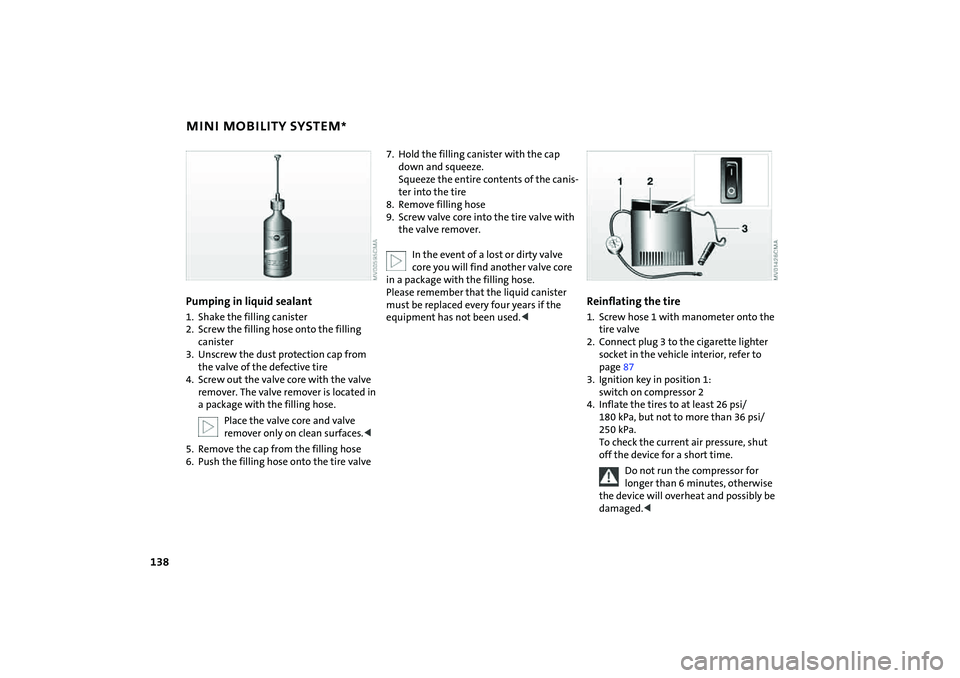
Reinflating the tire1. Screw hose 1 with manometer onto the
tire valve
2. Connect plug 3 to the cigarette lighter
socket in the vehicle interior, refer to
page87
3. Ignition key in position 1:
switch on compressor 2
4. Inflate the tires to at least 26 psi/
180 kPa, but not to more than 36 psi/
250 kPa.
To check the current air pressure, shut
off the device for a short time.
Do not run the compressor for
longer than 6 minutes, otherwise
the device will overheat and possibly be
damaged.<