display MINI COOPER CONVERTIBLE 2008 User Guide
[x] Cancel search | Manufacturer: MINI, Model Year: 2008, Model line: COOPER CONVERTIBLE, Model: MINI COOPER CONVERTIBLE 2008Pages: 176, PDF Size: 2.4 MB
Page 59 of 176
57
OVERVIEW REPAIRS OPERATIONCONTROLS DATA INDEX
AUTOMATIC TRANSMISSION WITH STEPTRONIC
*
Kickdown
Kickdown can be used to achieve maxi-
mum vehicle performance.
Press the accelerator pedal past the
increased resistance point at the full-throt-
tle position.
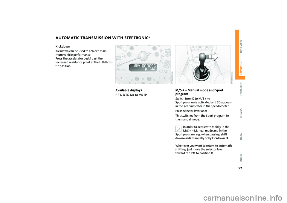
Available displaysP R N D SD M1 to M6 EP
M/S + – Manual mode and Sport
programSwitch from D to M/S + –:
Sport program is activated and SD appears
in the gear indicator in the speedometer.
Press selector lever once:
This switches from the Sport program to
the manual mode.
In order to accelerate rapidly in the
M/S + – Manual mode and in the
Sport program, e.g. when passing, shift
downwards manually or by kickdown.<
Whenever you want to return to automatic
shifting, just move the selector lever
toward the left to position D.
Page 60 of 176
58
AUTOMATIC TRANSMISSION WITH STEPTRONIC
*
Switching from M/S + – Manual mode into
the selector lever positions P, R and N is
only possible via D.Shifting with the selector lever>Briefly press the selector lever in the +
direction:
Transmission shifts up
>Briefly press the selector lever in the –
direction:
Transmission shifts down.
M1 to M6 appear in the gear indicator.
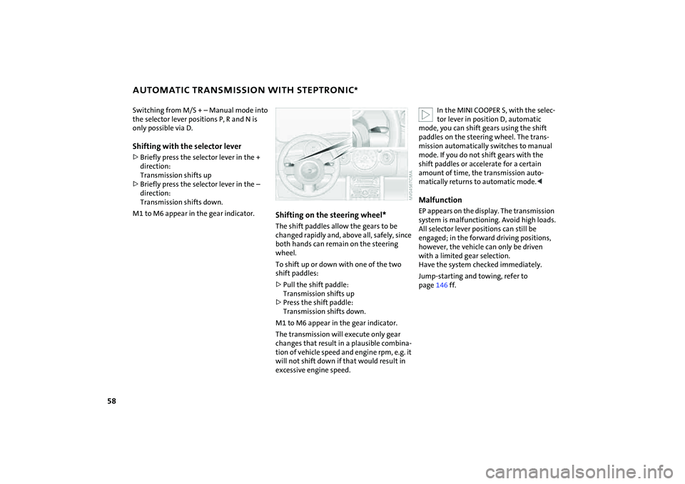
Shifting on the steering wheel*The shift paddles allow the gears to be
changed rapidly and, above all, safely, since
both hands can remain on the steering
wheel.
To shift up or down with one of the two
shift paddles:
>Pull the shift paddle:
Transmission shifts up
>Press the shift paddle:
Transmission shifts down.
M1 to M6 appear in the gear indicator.
The transmission will execute only gear
changes that result in a plausible combina-
tion of vehicle speed and engine rpm, e.g. it
will not shift down if that would result in
excessive engine speed.
In the MINI COOPER S, with the selec-
tor lever in position D, automatic
mode, you can shift gears using the shift
paddles on the steering wheel. The trans-
mission automatically switches to manual
mode. If you do not shift gears with the
shift paddles or accelerate for a certain
amount of time, the transmission auto-
matically returns to automatic mode.<
MalfunctionEP appears on the display. The transmission
system is malfunctioning. Avoid high loads.
All selector lever positions can still be
engaged; in the forward driving positions,
however, the vehicle can only be driven
with a limited gear selection.
Have the system checked immediately.
Jump-starting and towing, refer to
page146 ff.
Page 64 of 176
62
INSTRUMENT LIGHTING FOG LAMPS INTERIOR LAMPSTo control the instrument lighting, press
the button.Brighter displayPress the button until the desired bright-
ness is achieved.Dimmer displayPress the button briefly.
With each brief pressing of the button, the
illumination is dimmed step by step.
With the parking lamps/low beams
switched on:
Briefly press the switch upward or down-
ward.
Tap it again to switch off.Fog lamps*
The parking lamps or low beams
must be on. The green LED in the
switch lights up.
The fog lamps are on.
Rear fog lamp*
The low beams must be on. The
yellow LED in the switch lights up.
The rear fog lamp is on.
Observe all legal regulations concerning
the use of fog lamps.
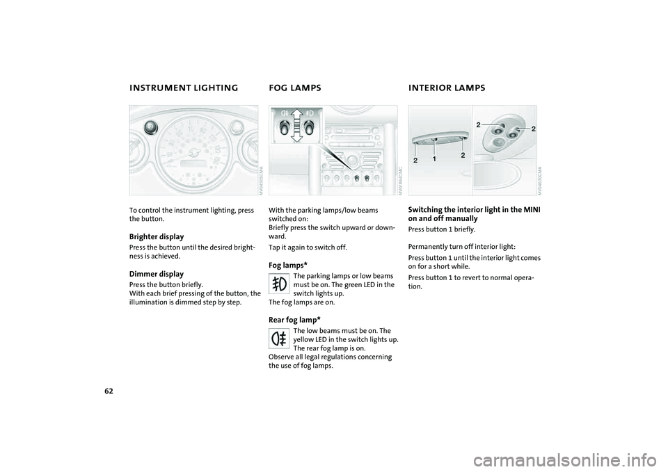
Switching the interior light in the MINI
on and off manuallyPress button 1 briefly.
Permanently turn off interior light:
Press button 1 until the interior light comes
on for a short while.
Press button 1 to revert to normal opera-
tion.
Page 69 of 176

67
OVERVIEW REPAIRS OPERATIONCONTROLS DATA INDEX
ODOMETER CLOCK FUEL GAUGE 1 Trip odometer/clock
2OdometerTrip odometer/clockTo switch between the trip odometer and
the clock:
Press the button.
To reset the trip odometer to zero:
Press the button until the trip odometer
shows zero.
To set the clock, refer to the information
below.OdometerWhen the ignition key is not in the ignition
lock, you can activate the displays shown in
the illustration by pressing the button in
the display elements.
Setting The clock must be shown on the display.
1. If necessary, press button 1 to display
the clock
2. Press button 1 for approx. 5 seconds to
activate the clock-setting mode
3. Press button 1 to select 12-hour or
24-hour mode
4. Wait approx. 5 seconds until the hours
display is shown
5. Press button 1 to set the hour
6. Wait approx. 5 seconds until the min-
utes display is shown
7. Press button 1 to set the minute.
The time entered is stored automatically
after approx. 1 minute.
In the speedometer or Cockpit Chrono
Pack*If the LED begins to be lit continuously,
there are approx. 2.1 gallons/8 liters of fuel
left in the tank.
Fuel tank capacity:
Approx. 13.2 gallons/50 liters.
When you switch on the ignition, the LED
lights up briefly to confirm that the system
is operational.
If the angle of the vehicle varies, for exam-
ple when you are driving in mountainous
areas, the needle may fluctuate slightly.
Refill the gas tank early. If you drive
to the last drop of fuel, engine func-
tions are not guaranteed and damage can
occur.<
Page 71 of 176
69
OVERVIEW REPAIRS OPERATIONCONTROLS DATA INDEX
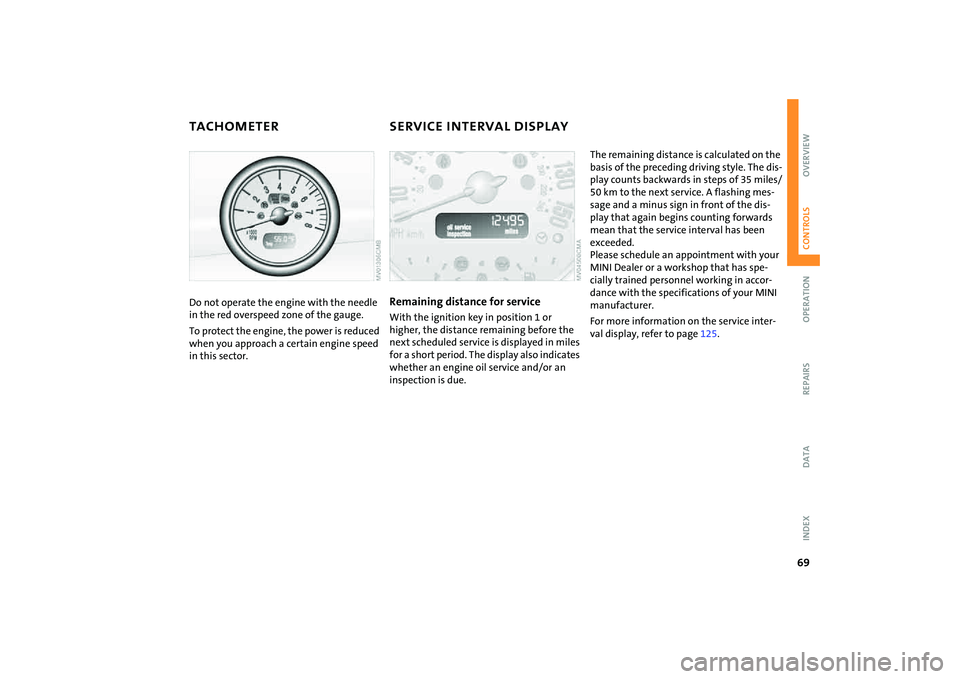
TACHOMETER SERVICE INTERVAL DISPLAYDo not operate the engine with the needle
in the red overspeed zone of the gauge.
To protect the engine, the power is reduced
when you approach a certain engine speed
in this sector.
Remaining distance for serviceWith the ignition key in position 1 or
higher, the distance remaining before the
next scheduled service is displayed in miles
for a short period. The display also indicates
whether an engine oil service and/or an
inspection is due.
The remaining distance is calculated on the
basis of the preceding driving style. The dis-
play counts backwards in steps of 35 miles/
50 km to the next service. A flashing mes-
sage and a minus sign in front of the dis-
play that again begins counting forwards
mean that the service interval has been
exceeded.
Please schedule an appointment with your
MINI Dealer or a workshop that has spe-
cially trained personnel working in accor-
dance with the specifications of your MINI
manufacturer.
For more information on the service inter-
val display, refer to page125.
Page 72 of 176

70
ONBOARD COMPUTER
*
Mode selection
You can use the button in the turn signal
indicator lever to retrieve information from
the onboard computer for display in the
tachometer. By pressing the button briefly,
you can call up a new function for display.
The order of the displays:
Outside temperature, range, average con-
sumption and current consumption, aver-
age speed and current speed.
If the vehicle is equipped with a navi-
gation system, you will find more
information on the onboard computer in
the Owner's Manual for Navigation Sys-
tem.<
Outside temperature If the vehicle is not equipped with an
onboard computer, only the outside tem-
perature is displayed.
Press the button in the turn indicator lever
to switch the display from outside temper-
ature to current speed and vice versa.
You can have the unit of measure set
to7 or6.
cally switches to the outside temperature
display.
In addition, a signal sounds and the display
flashes.
Black ice can occur at temperatures
above +36/377 as well. You
should therefore drive carefully on bridges
and shaded roads, for example; otherwise
there is an increased risk of an accident.<
With navigation system:
The temperature is displayed in the status
line of the navigation system, refer to the
Owner's Manual for Navigation System.
Current vehicle speedIf the vehicle is not equipped with an
onboard computer, only the current speed
is displayed.
Press the button in the turn indicator lever
to switch the display from outside temper-
ature to current speed and vice versa.RangeThe display shows a range estimate based
on the available fuel. The amount of fuel
remaining in the tank is measured, and the
range is estimated from your driving style
over the last 20 miles/30 km.
If the range displayed is less than
35 miles/50 km, be sure to refuel;
otherwise engine functions are not guaran-
teed and damage could occur.<
Page 73 of 176

71
OVERVIEW REPAIRS OPERATIONCONTROLS DATA INDEX
ONBOARD COMPUTER
*
Average speed, average fuel
consumption
To reset average consumption, average
speed:
Press the button in the turn signal indicator
lever for a long time.
The average consumption is determined
for the time during which the engine is run-
ning.
If the vehicle is equipped with a navi-
gation system, the displays are
shown in the area of the navigation sys-
tem.<
You can have a different unit of mea-
sure set.
mentally friendly you are currently driving.
You can have a different unit of mea-
sure set.<
Page 76 of 176

74
FLAT TIRE MONITOR The conceptAs you drive, the Flat Tire Monitor keeps
track of the tire inflation pressure in all four
tires. The system alerts you when there is a
substantial pressure loss in one of the tires
relative to another.
In the event of tire pressure loss, the rolling
radius of the tire changes, thereby affect-
ing the rotational speed of the wheels. This
change is detected, and a flat tire warning
is issued to the driver.System requirementsTo ensure the reliability of flat tire warn-
ings, the system must be initialized with
the correct tire inflation pressures.
Each time you correct the pressure in
a tire, or change a wheel or tire, the
system must be reinitialized.<
System limitations
The Flat Tire Monitor cannot alert you
to severe and sudden tire damage
caused by external factors, nor does it
detect the gradual and minor loss of pres-
sure in all four tires.<
The system could issue a false warning or
function in a delayed manner in the follow-
ing situations:
>System was not initialized
>You are driving on a snow-covered or
slippery road surface
>Sporty driving style: slip at the drive
wheels, high lateral acceleration
>You are driving with snow chains.
When driving with a space-saver spare tire,
the Flat Tire Monitor cannot function.
Initializing the system
Initialization is completed while you
are driving, but you can stop the car
at any time. Initialization is automatically
continued when you continue driving. Do
not initialize the system if you are driving
with snow chains or a space-saver spare
tire.<
1. Before a journey, start the engine, but do
not start driving.
2. Press the button until the indicator lamp
in the display elements lights up in yel-
low for several seconds.
3. Drive off.
Initialization is completed during the
drive, without any feedback issued.
Page 78 of 176
76
TIRE PRESSURE MONITOR
*
The concept
TPM checks the inflation pressures of the
four mounted tires. The system notifies you
if there is a significant loss of pressure in
one or more tires.System requirementsIn order to assure the reliable reporting of a
flat tire, the system must be reset while all
tire inflation pressures are correct.
Always use wheels with TPM electronics
and a metal valve. Otherwise, the system
may malfunction.
Each time a tire inflation pressure has
been corrected or a wheel or tire has
been changed, reset the system.<
System limitations
TPM cannot warn you in advance of
sudden severe tire damage caused by
outside influences.<
The system does not work correctly if it has
not been reset; for example, a flat tire may
be indicated even though the tire inflation
pressures are correct.
The system is inactive and cannot indicate
a flat tire if a wheel without TPM electron-
ics, such as a compact spare wheel, has
been mounted, or if TPM is temporarily
malfunctioning due to other systems or de-
vices using the same radio frequency.
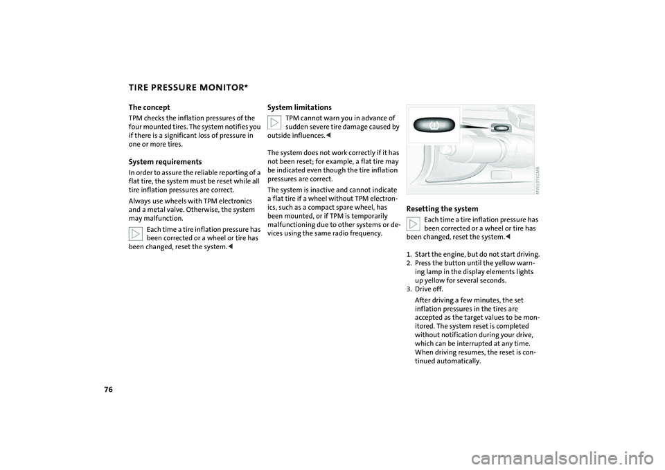
Resetting the system
Each time a tire inflation pressure has
been corrected or a wheel or tire has
been changed, reset the system.<
1. Start the engine, but do not start driving.
2. Press the button until the yellow warn-
ing lamp in the display elements lights
up yellow for several seconds.
3. Drive off.
After driving a few minutes, the set
inflation pressures in the tires are
accepted as the target values to be mon-
itored. The system reset is completed
without notification during your drive,
which can be interrupted at any time.
When driving resumes, the reset is con-
tinued automatically.
Page 82 of 176
80
AIRBAGStivated or activated, refer to Functional sta-
tus of the front passenger airbags below. <
Before transporting a child on the
front passenger seat, read the safety
notes and instructions under Transporting
children safely, refer to page50.
Adolescents and adults sitting in certain
positions could also deactivate the front
and side airbags for the front passenger;
the indicator lamp for the front passenger
airbags comes on. In such cases, the occu-
pant should change his or her sitting posi-
tion so that the front passenger airbags are
activated and the indicator lamp goes out.
If the airbags are not activated although
the seat occupant has changed his or her
position, have the occupant sit on a rear
seat. Do not attach covers, cushions, ball
mats or other items to the front passenger
seat unless they are specifically recom-
mended by the manufacturer of your MINI.
Do not place any objects under the seat
which could press against the seat from
below. Otherwise, a correct analysis of the
seat cushion is not ensured.<
Functional status of the front
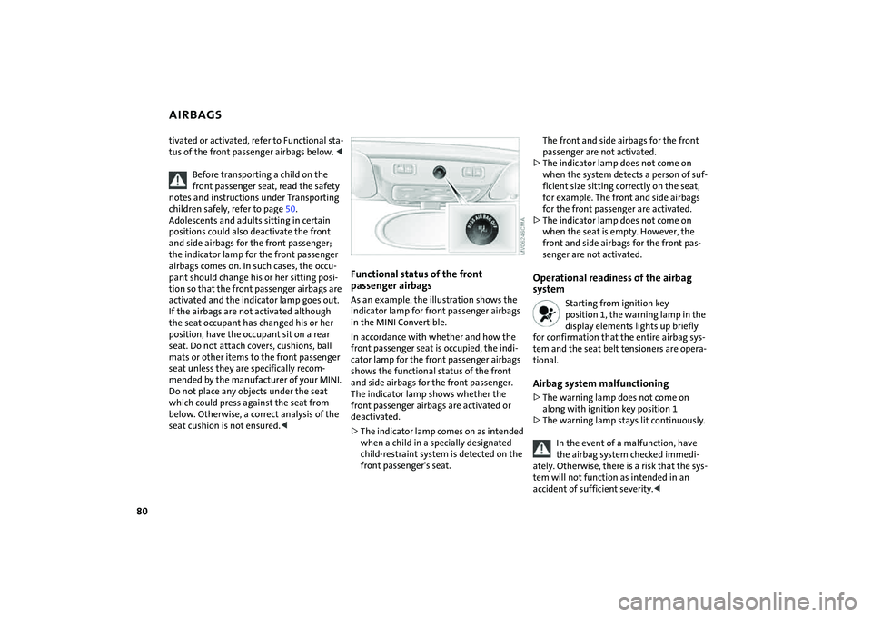
passenger airbagsAs an example, the illustration shows the
indicator lamp for front passenger airbags
in the MINI Convertible.
In accordance with whether and how the
front passenger seat is occupied, the indi-
cator lamp for the front passenger airbags
shows the functional status of the front
and side airbags for the front passenger.
The indicator lamp shows whether the
front passenger airbags are activated or
deactivated.
>The indicator lamp comes on as intended
when a child in a specially designated
child-restraint system is detected on the
front passenger's seat.
The front and side airbags for the front
passenger are not activated.
>The indicator lamp does not come on
when the system detects a person of suf-
ficient size sitting correctly on the seat,
for example. The front and side airbags
for the front passenger are activated.
>The indicator lamp does not come on
when the seat is empty. However, the
front and side airbags for the front pas-
senger are not activated. Operational readiness of the airbag
system
Starting from ignition key
position 1, the warning lamp in the
display elements lights up briefly
for confirmation that the entire airbag sys-
tem and the seat belt tensioners are opera-
tional.
Airbag system malfunctioning>The warning lamp does not come on
along with ignition key position 1
>The warning lamp stays lit continuously.
In the event of a malfunction, have
the airbag system checked immedi-
ately. Otherwise, there is a risk that the sys-
tem will not function as intended in an
accident of sufficient severity.<