display MINI COOPER CONVERTIBLE 2008 Owner's Manual
[x] Cancel search | Manufacturer: MINI, Model Year: 2008, Model line: COOPER CONVERTIBLE, Model: MINI COOPER CONVERTIBLE 2008Pages: 176, PDF Size: 2.4 MB
Page 87 of 176

85
OVERVIEW REPAIRS OPERATIONCONTROLS DATA INDEX
1 Air onto the windshield and onto the
side windows
2 Air for the upper body area87
3 Air for the front and rear footwells
4 Rear window defroster and windshield
heating
*
865 Interior temperature sensor, please keep
clear and unobstructed
6Recirculated air mode86
7 Cooling function86
8 Automatic air distribution and
volume86
9 Defrosting and demisting the windshield
and side windows8710 Temperature86
11 Display for air temperature and air
volume86
12 Air volume/Blower, switching air con-
ditioner on/off86
13 Individual air distribution87
AUTOMATIC CLIMATE CONTROL
*
Page 88 of 176
86
AUTOMATIC CLIMATE CONTROL
*
Automatic air distribution and volume
The LED is lit when the AUTO pro-
gram is on.
Automatic adjustment of the air distribu-
tion and volume, and adaptation of the
specified temperatures to external influ-
ences, e.g. outside temperature and insola-
tion.
In the automatic program (AUTO), the air
conditioning is activated automatically. To
create a pleasant air climate, the air tem-
perature coming from the vents in the
upper body area is lower than the air tem-
perature in the footwell.
Air volume/Blower
Switching automatic climate control
off/on
Press the left or right half of the
button to vary the air volume.
Automatic adjustment of the air volume is
deactivated.
Switching air conditioner on/off.
Press the left half of the button while the
blower is at the lowest setting. The blower,
heating and air conditioning are switched
off. All displays go out.
Switch the automatic climate control back
on by pressing any button.
Cooling function
The LED is lit when the cooling
function is on.
The air is cooled and dehumidified and,
depending on the temperature setting,
rewarmed.
The cooling function is automatically acti-
vated in the AUTO program.
Depending on the weather, the windshield
can fog up temporarily after the engine is
started.
When the air conditioning is on, con-
densation is formed which then exits
under the vehicle. Traces of condensed
water on the ground are therefore nor-
mal.<
Recirculated air mode
The LED is lit when the recirculated
ai r mode is on. Su ppl y of outside ai r
into the vehicle is blocked.
The air within the vehicle is recirculated.
In the automatic program (AUTO) in hot
weather conditions, the recirculated air
mode is activated temporarily to enable
faster cooling.
The LED for the recirculated air button is
not lit.
The recirculated air mode should not
be used constantly over a longer
period of time; otherwise the air quality in
the vehicle's interior will gradually deterio-
rate. If the windows fog up in the recircu-
lated air mode, turn the recirculated air
mode off and, if necessary, increase the air
supply.<
Rear window defroster and windshield
heating*
The LED comes on when the rear
window/windshield heating is on.
The heater switches off automatically after
a short time.
Temperature
Tap or turn the wheel in the
appropriate direction to change
the temperature step by step.
The figures in the display provide
a general indication of interior tempera-
ture. When you start the vehicle, the sys-
tem ensures that the selected temperature
is achieved as quickly as possible and then
maintained.
Permanent heating with maximum
power output at temperature selec-
tion HI. Permanent cooling at LO. With the
Page 107 of 176
105
OVERVIEW REPAIRSOPERATIONCONTROLS DATA INDEX
REFUELING
Always switch off the engine before
refueling; otherwise no fuel can be
added to the tank and the SERVICE ENGINE
SOON lamp may come on.<
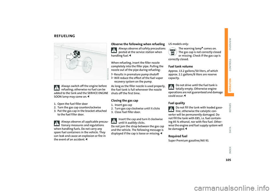
1. Open the fuel filler door
2. Turn the gas cap counterclockwise
3. Put the gas cap in the bracket attached
to the fuel filler door.
Always observe all applicable precau-
tionary measures and regulations
when handling fuels. Do not carry any
spare fuel containers in the vehicle. They
can leak and cause an explosion or fire in
the event of an accident.<
Observe the following when refueling
Always observe all safety precautions
posted at the service station when
handling fuel.<
When refueling, insert the filler nozzle
completely into the filler pipe. Pulling the
nozzle out of the pipe during refueling:
>Results in premature pump shutoff
>Will reduce the effect of the fuel vapor
recovery system on the pump.
As long as the filler nozzle is used properly,
the fuel tank is full whenever the nozzle
shuts off the first time.
Closing the gas cap1. Insert gas cap
2. Turn gas cap clockwise until it clicks
3. Close fuel filler door.
Insert the cap and turn it clockwise
until it audibly clicks.
Do not jam the strap between the gas cap
and the vehicle. The following message is
displayed if the cap is loose or missing.<
US models only:
The warning lamp
* comes on.
The gas cap is not correctly closed
or missing. Check if the gas cap is
correctly closed.
Fuel tank volumeApprox. 13.2 gallons/50 liters, of which
approx. 2.1 gallons/8 liters are reserve
capacity.
Do not drive until the fuel tank is
totally empty. Otherwise engine
operations are not guaranteed and damage
could occur.
line; otherwise the catalytic con-
verter will be permanently damaged. Do
not fill the tank with E85, i.e. fuel contain-
ing 85 % ethanol, nor with flex fuel. Other-
wise the engine and fuel supply system will
be damaged.<
Required fuelSuper Premium gasoline/AKI 91
Page 126 of 176
124
BRAKE SYSTEMBrake fluid level
The warning lamp comes on
although the parking brake is not
engaged:
The brake fluid level in the reservoir is too
low, refer to page16. At the same time,
brake pedal travel may become signifi-
cantly longer.
Have the system checked immediately.
If the brake fluid level is too low and brake
pedal travel has become longer, there may
be a defect in one of the brake system's
hydraulic circuits.
Canadian models display this
warning lamp.
If you continue driving, higher brake
application pressure may be neces-
sary, and there may be a slight pull to one
side. Brake pedal travel may also be longer.
Adapt your driving style accordingly.<
Page 127 of 176
125
OVERVIEW REPAIRSOPERATIONCONTROLS DATA INDEX
MINI MAINTENANCE SYSTEMThe MINI maintenance system helps main-
tain your vehicle's road safety and opera-
tional safety.
Please bear in mind that regular mainte-
nance is not only necessary for the safety of
your vehicle, but also plays a significant
role in maintaining the resale value of the
vehicle.
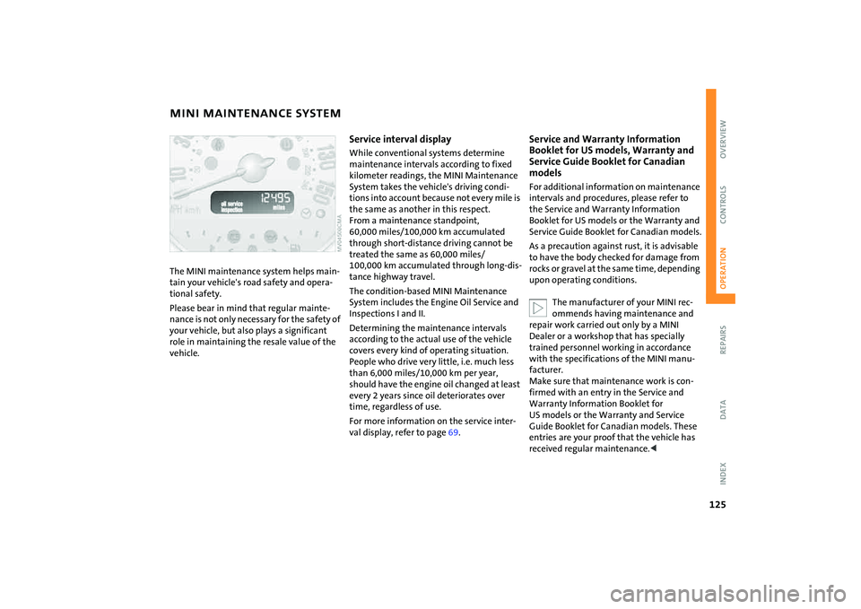
Service interval displayWhile conventional systems determine
maintenance intervals according to fixed
kilometer readings, the MINI Maintenance
System takes the vehicle's driving condi-
tions into account because not every mile is
the same as another in this respect.
From a maintenance standpoint,
60,000 miles/100,000 km accumulated
through short-distance driving cannot be
treated the same as 60,000 miles/
100,000 km accumulated through long-dis-
tance highway travel.
The condition-based MINI Maintenance
System includes the Engine Oil Service and
Inspections I and II.
Determining the maintenance intervals
according to the actual use of the vehicle
covers every kind of operating situation.
People who drive very little, i.e. much less
than 6,000 miles/10,000 km per year,
should have the engine oil changed at least
every 2 years since oil deteriorates over
time, regardless of use.
For more information on the service inter-
val display, refer to page69.
Service and Warranty Information
Booklet for US models, Warranty and
Service Guide Booklet for Canadian
models For additional information on maintenance
intervals and procedures, please refer to
the Service and Warranty Information
Booklet for US models or the Warranty and
Service Guide Booklet for Canadian models.
As a precaution against rust, it is advisable
to have the body checked for damage from
rocks or gravel at the same time, depending
upon operating conditions.
The manufacturer of your MINI rec-
ommends having maintenance and
repair work carried out only by a MINI
Dealer or a workshop that has specially
trained personnel working in accordance
with the specifications of the MINI manu-
facturer.
Make sure that maintenance work is con-
firmed with an entry in the Service and
Warranty Information Booklet for
US models or the Warranty and Service
Guide Booklet for Canadian models. These
entries are your proof that the vehicle has
received regular maintenance.<
Page 128 of 176

126
SOCKET FOR ONBOARD DIAGNOSTICS OBD CARING FOR YOUR VEHICLEPrimary components of exhaust emissions
can be checked by a device via the OBD
socket.
This socket is located to the left of the
driver's side, on the bottom of the instru-
ment panel underneath a cover.Exhaust emission values
The warning lamp comes on. The
exhaust emissions have deterio-
rated. Have the vehicle checked as
soon as possible.
Canadian models display this
warning lamp.
Under some circumstances, the lamp will
flash. This indicates severe engine misfir-
ing. In this case, you should reduce your
speed and visit your nearest MINI Dealer as
soon as possible. Severe engine misfiring
can quickly lead to serious damage of emis-
sions-related components, especially the
catalytic converter.
If the fuel filler cap is not properly
tightened, the OBD system may con-
clude that fuel vapors are escaping, causing
an indicator to light up. If the filler cap is
then tightened, the indicator should go out
within a few days.<
Suitable car-care products
Use the cleaning and car-care prod-
ucts available at your MINI Dealer.<
Washing your vehicleYou can wash your new MINI or MINI Con-
vertible in automatic car washes from the
beginning. Preference should be for cloth
car washes. If, due to lack of availability,
brush car washes must be used, modern
systems with soft brushes should be given
preference.
When using steam cleaners or high-
pressure cleaners, maintain sufficient
distance to the vehicle and do not exceed a
maximum temperature of 1407/606. If
the jet is too close or the pressure is too
high, this can lead to damage or initial
damage that can develop into more serious
damage. Water that enters vehicle compo-
nents can lead to damage over the long
term.
After washing the vehicle, apply the brakes
briefly to dry them, otherwise water can
reduce braking efficiency over the short
term and the brake rotors can corrode.
Switch the rain sensor off when passing
through an automatic car wash, refer to
page63. Failure to do so could result in
Page 129 of 176
127
OVERVIEW REPAIRSOPERATIONCONTROLS DATA INDEX
CARING FOR YOUR VEHICLEdamage caused by undesired wiper activa-
tion.
entering a car wash or a garage with
elevator ramp, remove the rod antenna.
To do so, grip the rod antenna at the base
and unscrew it from the antenna foot by
turning it to the left.<
Headlamps
When cleaning the headlamps,
please note: do not rub the head-
lamps dry and do not use any abrasive or
caustic cleaning products. Remove dirt and
contamination, such as insects, by soaking
with shampoo and then rinsing with plenty
of water. Always use a deicer spray to
remove accumulated ice and snow; never
use a scraper.<
Vehicle paintwork Regular care contributes greatly to driving
safety and value retention.
Environmental influences varying from one
region to the next can affect the vehicle
paintwork. Please base the frequency and
scope of car care on these various influ-
ences.Care of upholsteryDepressions that come about on the uphol-
stery material of the seats in daily use can
be brushed out using a slightly damp brush
against the grain.
The fact that velour lays down is not a qual-
ity defect, but rather is inevitable in the
case of home textiles or clothing materials.
In the case of strong sunlight and longer
parking periods, cover the seats or all win-
dows to prevent discoloration.
Care of special parts>Light-alloy wheels
*:
Use wheel cleaner especially during the
winter months, but do not use any
aggressive, acidic, strong alkali or rough
cleansers or steam jets above 1407/
606. Observe the manufacturer's
instructions
>Chrome parts
* such as the bonnet grille,
door handles, and similar parts:
Particularly if they were exposed to road
salt, clean these parts carefully with
plenty of water and shampoo additive, if
necessary. For additional treatment, use
chrome polish
>Rubber components:
Treat only with water or rubber care
products.
Do not use silicon sprays or other
silicon-containing care products,
otherwise noise and damage could
occur.<
>Plastic parts, artificial leather surfaces,
headliner, lamp lenses, cover glass over
display elements as well as matt-black
die-cast parts:
Clean these parts with water and plastic
care products, if necessary. Do not
dampen seats and the headliner.
Never use solvents such as lacquer thin-
Page 145 of 176
143
OVERVIEW REPAIRSOPERATION CONTROLS DATA INDEX
MINI MOBILITY SYSTEM
*
If an air pressure of 26 psi/180 kPa
cannot be reached, unscrew the
hose 1 and drive back and forth
about 33 ft/10 m so that the liquid seal-
ant is distributed in the tire. Afterwards
repeat the procedure.
If an air pressure of 26 psi/180 kPa is still
not reached, the tire is too badly dam-
aged. Please contact the nearest MINI
Dealer.<
5. Turn off compressor 2
6. Unscrew hose 1 from the tire valve
7. Store the MINI Mobility System back in
the vehicle.
The instructions for using the MINI
Mobility System are also given on the
equipment.<
Distributing liquid sealantImmediately drive for approx. 10 minutes,
so that the liquid sealant is uniformly dis-
tributed.
Do not exceed a speed of 40 mph /
60 km/h.
If possible do not drive at a speed lower
than 10 mph / 20 km/h.<
Checking tire inflation pressure1. After driving for approx. 10 minutes, pull
over at a suitable location
2. Screw hose with manometer back onto
the tire valve
3. Check the tire inflation pressures.
The tire inflation pressure must be
at least 18 psi/130 kPa. If it is not,
do not continue driving.<
If 18 psi/130 kPa are displayed:
4. Ignition key position 1:
switch on compressor 2. Correct the tire
inflation pressure to the specified value,
refer to the tire inflation pressure table
on page109
5. Replace the tire as soon as possible.
The use of the MINI Mobility System
may be ineffective with tire damage
larger than approx. 1/6 in/4 mm. Please
contact the nearest MINI Dealer if the tire
cannot be made drivable with the MINI
Mobility System.<
Driving on
Do not exceed the permitted maxi-
mum speed of 50 mph / 80 km/h;
otherwise an accident could happen.<
Replace the defective tire as soon as
possible and have the new wheel/tire
assembly balanced. Have the MINI Mobility
System refilled.<
Tire change setWhen changing a tire, always observe the
safety measures and the procedure for
changing tires starting on page137.
In case of a flat tire the tire change
set is not needed due to the availabil-
ity of the MINI Mobility System.<
Page 164 of 176

EVERYTHING FROM A TO Z
162
Configuring settings, refer to
Vehicle Memory49
Consumption, refer to
Average consumption71
Current fuel consumption71
Contents2
Control elements, refer to
Cockpit12
Convenience operation
convertible top37
from outside26
,27
glass sunroof, electric33
windows31
Convertible top35
care128
convenience operation37
electrical malfunction37
emergency closing37
malfunction37
Coolant122
indicator lamp16
level123
temperature gauge68
Coolant temperature68
Cooling
air conditioning mode86
cooling function83
Cooling function
air conditioning system83
automatic climate control86Cooling system, refer to
Capacities157
Copyright2
Cornering Brake Control
(CBC)72
warning lamp17
Correct tires112
Cosmetic mirror, refer to
Illuminated vanity mirror48
Cruise control65
buttons on the steering
wheel20
indicator lamp19
Cup holders, refer to Beverage
holders89
Curb weight, refer to
Weights155
,156
Current fuel consumption71
setting units71
Cylinders, refer to Engine
data152
D
Daily odometer, refer to Trip
odometer67
Dashboard, refer to Cockpit12
Dashboard lighting, refer to
Instrument lighting62Data
capacities157
dimensions153
engine152
technical152
weights155
Date of the Owner's Manual7
Daytime running lamps61
Defrosting and demisting
windows
air conditioning system84
automatic climate control87
Defrosting front windows, refer
to Defrosting and demisting
windows84
,87
Defrosting windows84
,87
air conditioning system83
automatic climate control86
Defrosting windshield, refer to
Defrosting and demisting
windows84
,87
Defrost setting, refer to
Defrosting and demisting
windows84,87
Demisting windows84
,87
Digital clock67
Dimensions153
,154
Dimming interior rearview
mirror102
Dipstick, engine oil121Directional turn signal,
refer to Turn signal
indicators61
Disc brakes103
Disengaging the locks, refer to
Unlocking26
Displacement, refer to Engine
data152
Display elements13
with navigation system or
Cockpit Chrono Pack14
Display lighting, refer to
Instrument lighting62
Disposal
coolant122
vehicle battery144
Distance covered, refer to
Odometer67
Distance warning, refer to Park
Distance Control (PDC)81
Door keys24
Door lock27
Doors, locking and unlocking
acknowledgment
signals26
,27
from inside28
from outside26
DOT quality grades112
Draft-free ventilation84
,87
Drink holders, refer to Beverage
holders89
Page 167 of 176

EVERYTHING FROM A TO Z
165
OVERVIEW REPAIRS OPERATION CONTROLS DATA INDEX
I
Ice warning, refer to Outside
temperature warning70
Ignition53
Ignition key24
Ignition key positions, refer to
Ignition lock53
Ignition lock53
Illuminated vanity mirror48
Imitation leather127
Imprint2
Index160
Indicator/warning lamp
airbags80
ASC73
brakes124
coolant temperature68
DSC73
fasten safety belts46
Flat Tire Monitor75
fog lamps62
reserve fuel capacity67
,68
Indicator and warning lamps
Tire Pressure Monitor
TPM77
Indicator and warning lamps,
overview16
Individual air distribution87
Individual settings, refer to
Vehicle Memory49Inflation pressure, refer to Tire
inflation pressure108
Inflation pressure monitor,
refer to Flat Tire Monitor74
Inflation pressure monitoring,
refer to Tire Pressure Monitor
TPM76
Inspection69
Instrument cluster, refer to
Display elements13
Instrument lighting62
Instrument panel, refer to
Cockpit12
Integrated universal remote
control91
Interior lamp, remote
control26
Interior lamps62
Interior rearview mirror48
automatic dimming102
Interlock, refer to Steering
locked53
Intermittent operation of the
wipers63
Interval
display, service125
J
Jack137
,141
points140Jack, refer to Tire change set
MINI Mobility System141
Run-Flat Tires115
space-saver spare tire137
Jacking points140
Jets, refer to Ventilation84
,87
Jets, refer to Windshield
washer jets64
John Cooper Works Kit152
Jump-starting146
K
Keys24
Kickdown57
Knock control105
L
Lamp defect133
Lamp replacement, refer to
Lamps and bulbs133
Lamps, refer to Parking lamps/
Low beams60
Lamps and bulbs133
Lashing eyelets, refer to
Securing the load97
LATCH child-restraint fixing
system52
Leather care128
LEDs light-emitting diodes136
Length, refer to
Dimensions153
,154License plate lamp, bulb
replacement136
Lifting handle, space-saver
spare tire137
Light-alloy wheels, care127
Light-emitting diodes
(LEDs)136
Lighter90
Lighting
lamps and bulbs133
Lighting of the instruments62
Lights on warning61
Light switch60
Loading
securing cargo97
stowing cargo97
Loading the vehicle95
Loads, refer to Loading cargo95
Load securing devices, refer to
Securing the load97
Locking
from inside28
from outside26
Locking/unlocking the vehicle,
acknowledgment
signals26
,27
Low beams60
bulb replacement134
Lower back support, refer to
Lumbar support44