service indicator MINI COOPER CONVERTIBLE 2015 Owners Manual
[x] Cancel search | Manufacturer: MINI, Model Year: 2015, Model line: COOPER CONVERTIBLE, Model: MINI COOPER CONVERTIBLE 2015Pages: 231, PDF Size: 5.56 MB
Page 16 of 231

Displays1Tachometer 67
with indicator and warning lights 152Display for▷Current speed 66▷Indicator/warning lights 153Resetting the trip odometer 664Display for▷Steptronic transmission position 63▷On-board computer 67▷Service requirements 71▷Odometer and trip odometer 66▷Flat Tire Monitor 84▷Tire Pressure Monitor 86▷Settings and information 69▷Personal Profile settings 215Instrument lighting 786Speedometer with indicator and warning
lights 157Fuel gauge 678Radio display9Radio Radio MINI Boost CD 126Seite 14AT A GLANCECockpit14
Online Edition for Part no. 01 40 2 961 029 - II/15
Page 33 of 231

The indicator lamp lights up: replace
the remote control battery.
Replacing the battery
The remote control for Comfort Access contains
a battery that will need to be replaced from
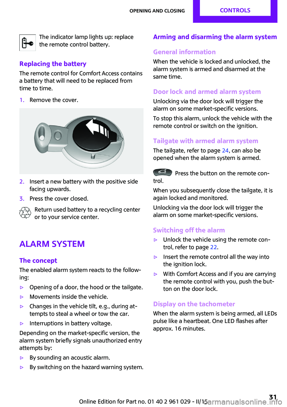
time to time.1.Remove the cover.2.Insert a new battery with the positive side
facing upwards.3.Press the cover closed.
Return used battery to a recycling center
or to your service center.
Alarm system
The concept
The enabled alarm system reacts to the follow‐
ing:
▷Opening of a door, the hood or the tailgate.▷Movements inside the vehicle.▷Changes in the vehicle tilt, e.g., during at‐
tempts to steal a wheel or tow the car.▷Interruptions in battery voltage.
Depending on the market-specific version, the
alarm system briefly signals unauthorized entry
attempts by:
▷By sounding an acoustic alarm.▷By switching on the hazard warning system.Arming and disarming the alarm system
General information
When the vehicle is locked and unlocked, the
alarm system is armed and disarmed at the
same time.
Door lock and armed alarm systemUnlocking via the door lock will trigger the
alarm on some market-specific versions.
To stop this alarm, unlock the vehicle with the
remote control or switch on the ignition.
Tailgate with armed alarm system The tailgate, refer to page 24, can also be
opened when the alarm system is armed.
Press the button on the remote con‐
trol.
When you subsequently close the tailgate, it is
again locked and monitored.
Unlocking via the door lock will trigger the
alarm on some market-specific versions.
Switching off the alarm
▷Unlock the vehicle using the remote con‐
trol, refer to page 22.▷Insert the remote control all the way into
the ignition lock.▷With Comfort Access and if you are carrying
the remote control with you, push the but‐
ton on the door lock.
Display on the tachometer
When the alarm system is being armed, all LEDs
pulse like a heartbeat. One LED flashes after
approx. 16 minutes.
Seite 31Opening and closingCONTROLS31
Online Edition for Part no. 01 40 2 961 029 - II/15
Page 50 of 231

The shoulder strap's anchorage point will be
correct for adult seat occupants of every build if
the seat is correctly adjusted, refer to page 45.
Unbuckling the belt1.Hold the belt firmly.2.Press the red button in the belt buckle.3.Guide the belt back into its reel.
MINI Convertible: rear belt guide
When fastening the safety belts on the rear
seats, ensure that the belt guide loop, arrow, is
closed.
Safety belt reminder for driver's seat
and front passenger seat
The indicator lamps light up and a sig‐
nal sounds. Check whether the safety
belt has been fastened correctly.
Damage to safety belts In the case of strain caused by accidents or
damage:
Have the safety belts, including the safety belt tensioners, replaced and have the belt anchors checked.
Checking and replacing safety belts
Have the work performed only by your
service center; otherwise, it cannot be ensured
that this safety feature will function properly. ◀
Head restraints
Correctly set head restraint
A correctly adjusted head restraint reduces the
risk of spinal injury in the event of an accident.
Adjusting the head restraint
Correctly adjust the head restraints of all
occupied seats; otherwise, there is an increased
risk of injury in an accident. ◀
Height Adjust the head restraint so that its center is
approx. at ear level.
Distance
Adjust the distance so that the head restraint is as close as possible to the back of the head.
Height adjustment
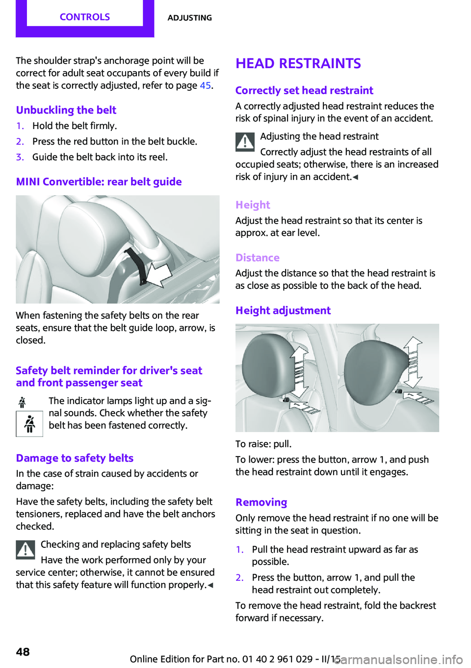
To raise: pull.
To lower: press the button, arrow 1, and push
the head restraint down until it engages.
Removing
Only remove the head restraint if no one will be
sitting in the seat in question.
1.Pull the head restraint upward as far as
possible.2.Press the button, arrow 1, and pull the
head restraint out completely.
To remove the head restraint, fold the backrest
forward if necessary.
Seite 48CONTROLSAdjusting48
Online Edition for Part no. 01 40 2 961 029 - II/15
Page 71 of 231

Settings and informationOperating concept
Some settings and information can only be cre‐
ated or opened while the ignition is switched
on, the vehicle is standing, and the doors are
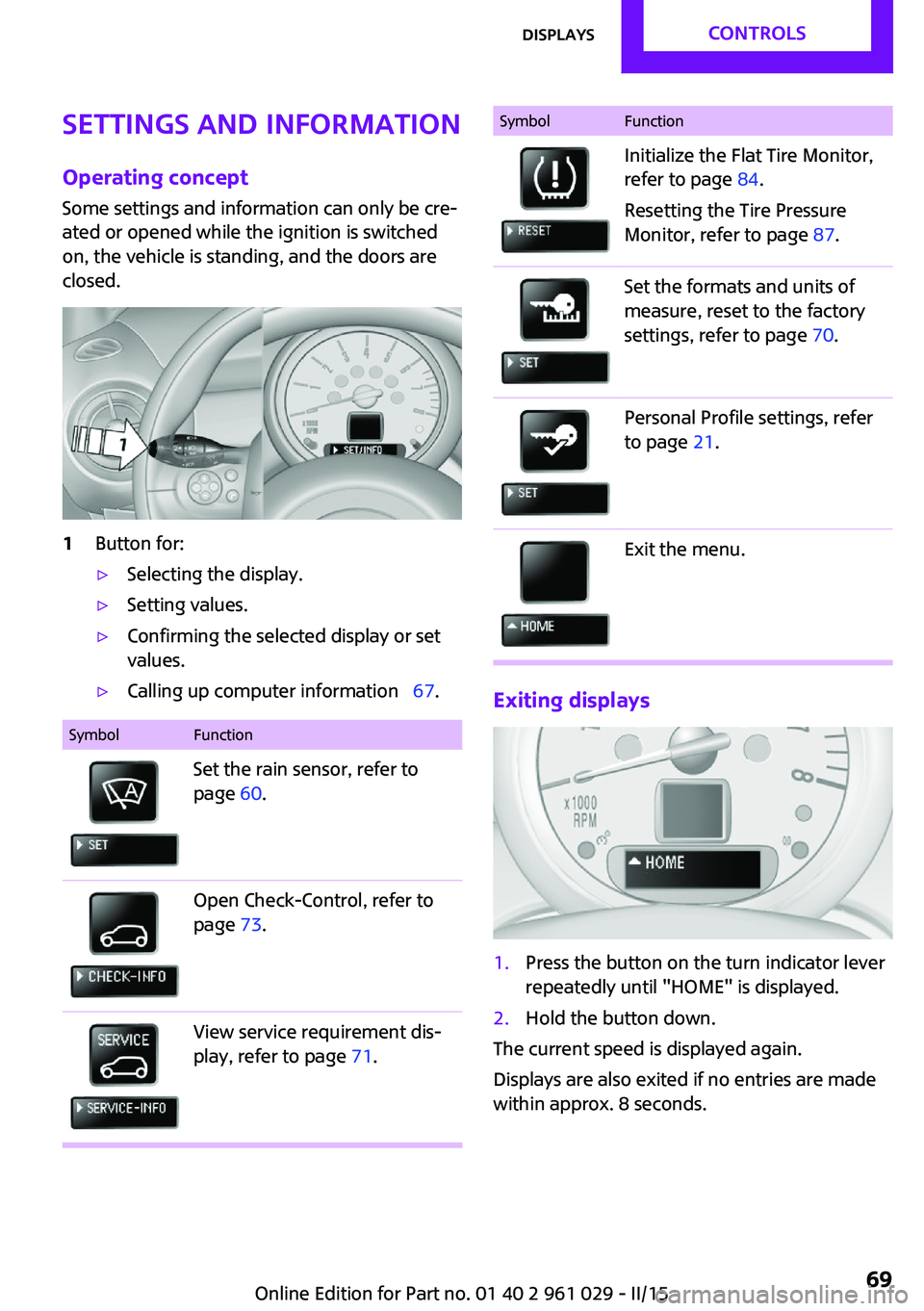
closed.1Button for:▷Selecting the display.▷Setting values.▷Confirming the selected display or set
values.▷Calling up computer information 67.SymbolFunctionSet the rain sensor, refer to
page 60.Open Check-Control, refer to
page 73.View service requirement dis‐
play, refer to page 71.SymbolFunctionInitialize the Flat Tire Monitor,
refer to page 84.
Resetting the Tire Pressure
Monitor, refer to page 87.Set the formats and units of
measure, reset to the factory
settings, refer to page 70.Personal Profile settings, refer
to page 21.Exit the menu.
Exiting displays
1.Press the button on the turn indicator lever
repeatedly until "HOME" is displayed.2.Hold the button down.
The current speed is displayed again.
Displays are also exited if no entries are made
within approx. 8 seconds.
Seite 69DisplaysCONTROLS69
Online Edition for Part no. 01 40 2 961 029 - II/15
Page 73 of 231

Resetting to factory settings
The settings for formats and units of measure
can be reset to the factory settings. The settings
are stored for the remote control in use.1.Press the button on the turn indicator lever
repeatedly until "SET/INFO" is displayed.2.Press and hold the button until the display
changes.3.Press the button repeatedly until the sym‐
bol and "SET" are displayed.4.Press and hold the button until the display
changes.5.Press the button repeatedly until "RESET"
appears on the display.6.Press and hold the button until the display
changes to the first setting option.
The settings are reset.
Clock
Setting the time Radio MINI Boost CD: set the time, refer to
page 128.
Date
Setting the date
Radio MINI Boost CD: set the date, refer to
page 128.
Service requirements
The remaining driving distance and the date of
the next scheduled service are displayed briefly
Seite 71DisplaysCONTROLS71
Online Edition for Part no. 01 40 2 961 029 - II/15
Page 74 of 231

immediately after you start the engine or
switch on the ignition.
The current service requirements can be read
out from the remote control by the service spe‐
cialist.
Displaying the vehicle check
For certain maintenance operations, you can
view the distance remaining or the due date for
that operation in the tachometer.1.Switch on the ignition, refer to page 56.2.Press the button on the turn indicator lever
repeatedly until "SET/INFO" is displayed.3.Press and hold the button until the display
changes.4.Press the button repeatedly until the corre‐
sponding symbol and "SERVICE-INFO" are
displayed.5.Press and hold the button until the display
changes.6.Press the button to display the individual
service requirement items.Possible displays1Button for selecting the information.SymbolFunctionService requirementsEngine oilRoadworthiness testFront brake padsRear brake padsBrake fluidSeite 72CONTROLSDisplays72
Online Edition for Part no. 01 40 2 961 029 - II/15
Page 84 of 231

▷Do not apply adhesive materials to the air‐
bag cover panels, cover them or modify
them in any way.▷Never modify either the individual compo‐
nents or the wiring in the airbag system.
This also applies to steering wheel covers,
the dashboard, the seats, the roof pillars
and the sides of the headliner. ◀
Even when all instructions are followed closely,
injury from contact with the airbags cannot be
ruled out in certain situations.
The ignition and inflation noise may lead to
short-term and, in most cases, temporary hear‐
ing impairment in sensitive individuals.
In the case of a malfunction, deactivation
and after triggering of the airbags
Do not touch the individual components imme‐
diately after the system has been triggered;
otherwise, there is the danger of burns.
Only have the airbags checked, repaired or dis‐
mantled and the airbag generator scrapped by
your service center or a workshop that has the
necessary authorization for handling explo‐
sives.
Non-professional attempts to service the sys‐
tem could lead to failure in an emergency or
undesired triggering of the airbag, either of
which could result in injury. ◀
Warning notices and information about the air‐
bags can also be found on the sun visors.
Automatic deactivation of the front
passenger airbags
The occupation of the seat is detected by eval‐
uating the impression on the occupied seat sur‐
face of the front passenger seat.
The front and side airbags on the front passen‐
ger side are activated or deactivated accord‐
ingly by the system.
The indicator lamp above the interior rearview
mirror, refer to page 83, shows the current
status of the front passenger airbags, deacti‐
vated or activated.
Leave feet in the footwell
Make sure that the front passenger keeps
his or her feet in the footwell; otherwise, the
front passenger airbags may not function prop‐
erly. ◀
Child restraint fixing system in the front
passenger seat
Before transporting a child on the front passen‐
ger seat, read the safety and operating instruc‐
tions under Transporting children safely, refer
to page 51.◀
Malfunction of the automatic deactivation system
When transporting older children and adults,
the front passenger airbags may be deactivated
in certain sitting positions. In this case, the indi‐
cator lamp for the front passenger airbags
lights up.
In this case, change the sitting position so that
the front passenger airbags are activated and
the indicator lamp goes out.
If it is not possible to activate the airbags, have
the person sit in the rear.
To make sure that occupation of the seat cush‐
ion can be detected correctly:▷Do not attach seat covers, seat cushion
padding, ball mats, or other items to the
front passenger seat unless they are specifi‐
cally recommended by the manufacturer of
your MINI.▷Do not place electronic devices on the pas‐
senger seat if a child restraint fixing system
is mounted on the seat.▷Do not place objects under the seat that
could press against the seat from below.Seite 82CONTROLSSafety82
Online Edition for Part no. 01 40 2 961 029 - II/15
Page 87 of 231

Do not initialize the system when driving with
snow chains.1.Start the engine, but do not start driving.2.Press the button on the turn indicator lever
repeatedly until "SET/INFO" is displayed.3.Press and hold the button until the display
changes.4.Press the button repeatedly until the corre‐
sponding symbol and "RESET" are dis‐
played.5.Press and hold the button until the display
changes.6.Drive away.
Initialization is completed while the car is
traveling without feedback being given.
Indication of a flat tire
The warning lights come on in yellow
and red. In addition, a signal sounds.
There is a flat tire or a major loss in tire inflation
pressure.1.Reduce your speed and stop cautiously.
Avoid sudden braking and steering maneu‐
vers.2.Check whether the vehicle is fitted with
regular tires or run-flat tires.
Run-flat tires, refer to page 166, are la‐
beled with a circular symbol containing the
letters RSC marked on the tire sidewall.
Do not continue driving without run-flat
tires
Do not continue driving if the vehicle is not
equipped with run-flat tires; continued driving
may result in serious accidents. ◀
When a flat tire is indicated, DSC Dynamic Sta‐
bility Control is switched on if necessary.
Actions in the event of a flat tire
Normal tires
1.Identify the damaged tire.
Do this by checking the inflation pressure in
all four tires.
The tire pressure gauge of the Mobility Sys‐
tem, refer to page 167, can be used for this
purpose.
If the tire inflation pressure in all four tires is
correct, the Flat Tire Monitor may not have
been initialized. In this case, initialize the
system.
If an identification is not possible, please
contact the service center.2.Rectify the flat tire using the Mobility Sys‐
tem, refer to page 167, or replace the
damaged wheel, refer to page 184.
Run-flat tires
You can continue driving with a damaged tire
at speeds up to 50 mph/80 km/h.
Seite 85SafetyCONTROLS85
Online Edition for Part no. 01 40 2 961 029 - II/15
Page 166 of 231

for example, requires a minimum tread depth
of only 0.063 in/1.6 mm. At tread depths less
than 0.12 in/3 mm, there is a great danger of
hydroplaning even in low water depths and at
raised speeds.
Winter tires The suitability of winter tires for winter driving
is reduced noticeably when their tread depth
becomes less than 0.16 in/4 mm.
Minimum tread depth
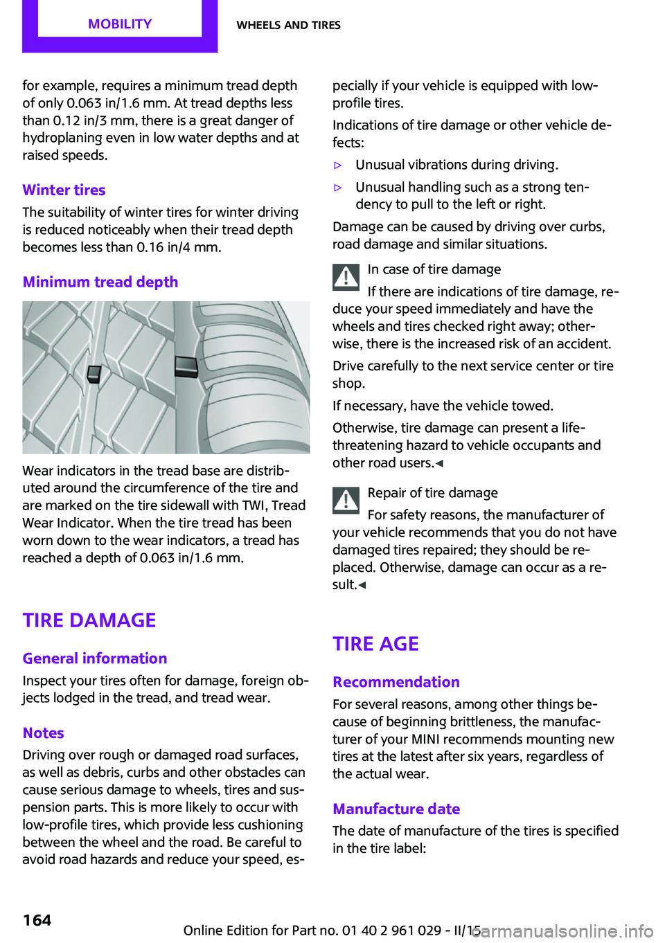
Wear indicators in the tread base are distrib‐
uted around the circumference of the tire and
are marked on the tire sidewall with TWI, Tread
Wear Indicator. When the tire tread has been
worn down to the wear indicators, a tread has
reached a depth of 0.063 in/1.6 mm.
Tire damage
General information Inspect your tires often for damage, foreign ob‐
jects lodged in the tread, and tread wear.
Notes
Driving over rough or damaged road surfaces,
as well as debris, curbs and other obstacles can
cause serious damage to wheels, tires and sus‐
pension parts. This is more likely to occur with
low-profile tires, which provide less cushioning
between the wheel and the road. Be careful to
avoid road hazards and reduce your speed, es‐
pecially if your vehicle is equipped with low-
profile tires.
Indications of tire damage or other vehicle de‐
fects:▷Unusual vibrations during driving.▷Unusual handling such as a strong ten‐
dency to pull to the left or right.
Damage can be caused by driving over curbs,
road damage and similar situations.
In case of tire damage
If there are indications of tire damage, re‐
duce your speed immediately and have the
wheels and tires checked right away; other‐
wise, there is the increased risk of an accident.
Drive carefully to the next service center or tire
shop.
If necessary, have the vehicle towed.
Otherwise, tire damage can present a life-
threatening hazard to vehicle occupants and
other road users. ◀
Repair of tire damage
For safety reasons, the manufacturer of
your vehicle recommends that you do not have
damaged tires repaired; they should be re‐
placed. Otherwise, damage can occur as a re‐
sult. ◀
Tire age RecommendationFor several reasons, among other things be‐
cause of beginning brittleness, the manufac‐
turer of your MINI recommends mounting new
tires at the latest after six years, regardless of
the actual wear.
Manufacture date The date of manufacture of the tires is specified
in the tire label:
Seite 164MOBILITYWheels and tires164
Online Edition for Part no. 01 40 2 961 029 - II/15
Page 203 of 231

12CauseHow to respondLights up in red:Convertible top control failed!The convertible top position and lock
cannot be detected. When the
convertible top has been securely
locked, you can continue driving.
Close the convertible top/sliding sun‐
roof manually, refer to page 36.
Have the system checked by the
service center.Lights up in yellow:Convertible top drive overheated!Allow the convertible top drive to
cool, refer to page 35.Sliding sunroof/convertible top.Failure of the convertible top/sliding
sunroof control. Close the
convertible top/sliding sunroof man‐
ually, refer to page 36. Contact your
service center.Tailgate of the MINI Convertible is not
closedClose the tailgate.MINI Roadster: the indicator lamp lights
up. Fully open the semi-automatic
convertible top.MINI Roadster: the indicator lamp lights
up. The semi-automatic convertible top
movement is completed. Close the
convertible top using the handleLights up in yellow:The rear spoiler is extended, refer to
page 93.Before driving into the car wash, re‐
tract the rear spoiler.The rear spoiler cannot be fully extended,
refer to page 93.Drive slowly and have the system
checked by the nearest service cen‐
ter.Seite 201Indicator/warning lampsMOBILITY201
Online Edition for Part no. 01 40 2 961 029 - II/15