tow MINI Countryman 2011 (Mini Connected) Owner's Guide
[x] Cancel search | Manufacturer: MINI, Model Year: 2011, Model line: Countryman, Model: MINI Countryman 2011Pages: 254, PDF Size: 3.84 MB
Page 128 of 254
NAVIGATIONWhat to do if…
126
What to do if…
What to do if…
>The current position cannot be displayed?
The position is in an unrecognized region, in
a poor reception area, or the system is in the
process of determining the position. Recep-
tion is best when you have an unobstructed
view to the sky.
> The route guidance does not accept an
address without the street name?
A downtown area cannot be determined for
the town or city that has been entered. Input
any street in the selected town/city and start
route guidance.
> The route guidance does not accept a desti-
nation?
The destination data is not contained in the
navigation data. Select a destination that is
as close as possible to the original.
> The letters for a destination cannot be
selected during destination entry?
Stored data do not contain the data of the
destination. Select a de stination that is as
close as possible to the original.
> The map view is displayed in grayscale?
When the traffic info map is activated, the
picture on the Control Display is switched to
a grayscale. This permits an optimized
depiction of traffic information.
> Voice instructions ar e no longer issued
before intersections during route guidance?
The area has not been fully recorded yet, or
you have left the recommended route and
the system requires a few seconds to calcu-
late a new route suggestion.
> The navigation system does not react to
entries?
If the battery was disconnected, it takes
about 10 minutes before the system is once
again operational.
Page 176 of 254
CommunicationsMobile phone preparation Bluetooth
174
Adjusting volume
Turn knob during announcement.
>The volume remains the same, even if the
volume of other audi o sources is changed.
> The volume is stored for the remote control
currently in use.
Notes
Do not use the voice activation system to initiate
an emergency call. In st ressful situations, the
voice and vocal pitch can change. This can
unnecessarily delay the establishment of a tele-
phone connection.
Ambient conditions
> Say the commands, numbers and letters
smoothly and with normal volume, empha-
sis and speed.
> Always say commands in the language of
the voice activation system. The language
for voice operation is preset and can not be
changed over the Control Display.
> Keep doors, windows, glass sunroof
*/pan-
oramic sunroof
*, or convertible top* closed
to avoid noise interference.
> Avoid ambient noise in the vehicle while
speaking.
Snap-in adapter*
Installation location
In the center armrest.
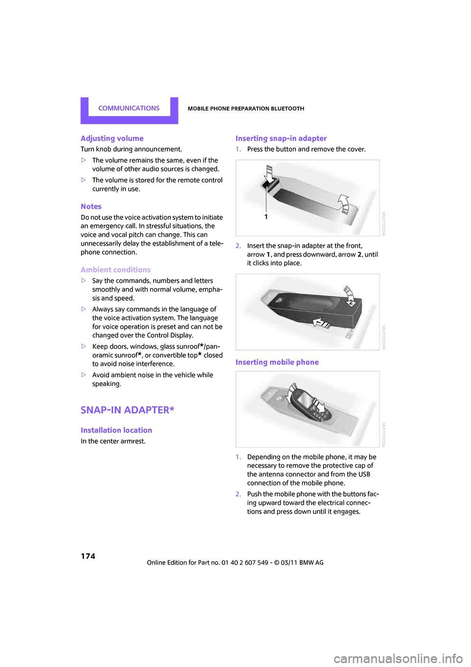
Inserting snap-in adapter
1.Press the button and remove the cover.
2. Insert the snap-in ad apter at the front,
arrow 1, and press downward, arrow 2, until
it clicks into place.
Inserting mobile phone
1. Depending on the mobile phone, it may be
necessary to remove the protective cap of
the antenna connector and from the USB
connection of the mobile phone.
2. Push the mobile phone with the buttons fac-
ing upward toward the electrical connec-
tions and press down until it engages.
Page 197 of 254

Wheels and tiresMOBILITY
195
failure. The grade C corresponds to a level of
performance which all passenger car tires must
meet under the Federal Motor Vehicle Safety
Standard No. 109. Grades B and A represent lev-
els of performance on the laboratory test wheel
that exceed the minimum required by law.The temperature grade for this tire is
established for a tire that is properly
inflated and not overloaded. Excessive speed,
underinflation, or excessive loading, either sep-
arately or in combinat ion, can cause heat
buildup and possible tire failure. <
RSC - run-flat tires*
You will recognize run-flat tires by a circular
symbol containing the letters RSC on the side of
the tire, page196.
M+S
Winter and all-season tires.
These have better winter properties than sum-
mer tires.
XL
Designation for specia lly reinforced tires.
Tire condition
Inspect your tires regula rly for tread wear, signs
of damage and for foreig n objects lodged in the
tread. Check the tread depth.
Tread depth
The tread depth should not drop below 0.12 in/
3 mm, although, for exam ple, European legisla-
tion only specifies a minimum tread depth of
0.063 in/1.6 mm. At tread depths below 0.12 in/
3 mm there is an increased risk of high-speed
hydroplaning, even when only small amounts of
water are present on the road surface.
Winter tires
When winter tires wear down past a tread depth
of 0.16 in/4 mm, they become perceptibly less
suitable for winter conditions. In the interest of
safety, new tires should be installed.
Minimum tread depth
Wear indicators in the base of the tread groove
are distributed around the tire's circumference;
the letters TWI, for Tread Wear Indicator, on the
tire's sidewalls identify tires that incorporate
these wear indicators. If the tire tread has been
driven down to the wear indicators, a tread
depth of 0.063 in/1.6 mm has been reached.
Tire damage
Due to low-profile tires, please note that wheels,
tires and suspensions parts are more susceptible
to road hazards and consequential damages.
Unusual vibrations encountered during normal
vehicle operation can indicate tire failure or
some other vehicle defect . This can, for exam-
ple, be caused by driving over curbs. The same
applies to any other ab normal road behavior,
such as pulling severely to the right or left.
In these cases, reduce speed immediately
and have wheels an d tires thoroughly
checked. To do so, drive carefully to the nearest
MINI dealer or tire shop that works according to
MINI repair procedures with correspondingly
trained personnel. If necessary, have the vehicle
towed there.
Otherwise, tire damage can be extremely dan-
gerous for vehicle occupants and other road
users. <
Page 201 of 254

Under the hoodMOBILITY
199
Important parts of the engine compartment
1Vehicle identification number*
2Battery, under the cover 219
3 Engine oil dipstick 199
4 Engine oil filler neck 200 5
Coolant expansion tank 200
6 Engine compartment fuse box 216
7 Reservoir for washer fl uid for the headlamp
and window washer system 53
Engine oil
The engine oil consumption is dependent on
driving style and driving conditions.
Check the engine oil level regularly, e.g. when
refueling.
Checking engine oil level
1.With the vehicle's engi ne at normal operat-
ing temperature, i.e. after uninterrupted
driving for at least 6 miles/10 km, park the
vehicle on a level surface.
2. Switch off the engine.
3. Pull the dipstick out after approx. 5 minutes
and wipe it off with a lint-free cloth, paper
towel or similar material. 4.
Carefully push the dipstick all the way into
the guide tube and pull it out again.
The oil level should be between the two
marks on the dipstick.
The oil quantity corresponding to the difference
between the two marks on the dipstick is
1 US quart/1 liter.
Page 210 of 254
MOBILITYReplacing components
208
Replacing components
Wiper blades
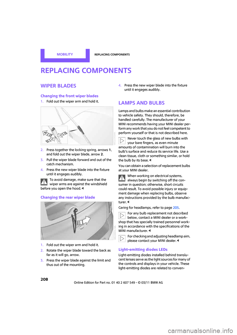
Changing the front wiper blades
1.Fold out the wiper arm and hold it.
2. Press together the lo cking spring, arrows1,
and fold out the wiper blade, arrow 2.
3. Pull the wiper blade forward and out of the
catch mechanism.
4. Press the new wiper blade into the fixture
until it engages audibly.
To avoid damage, make sure that the
wiper arms are against the windshield
before you open the hood. <
Changing the rear wiper blade
1.Fold out the wiper arm and hold it.
2. Rotate the wiper blade toward the back as
far as it will go, arrow.
3. Press the wiper blade against the limit and
thus out of the mounting. 4.
Press the new wiper blade into the fixture
until it engages audibly.
Lamps and bulbs
Lamps and bulbs make an essential contribution
to vehicle safety. They should, therefore, be
handled carefully. The manufacturer of your
MINI recommends having your MINI dealer per-
form any work that you do not feel competent to
perform yourself or that is not described here.
Never touch the glass of new bulbs with
your bare fingers, as even minute
amounts of contaminatio n will burn into the
bulb's surface and reduce its service life. Use a
clean tissue, cloth or some thing similar, or hold
the bulb by its base. <
You can obtain a selectio n of replacement bulbs
at your MINI dealer.
When working on electrical systems,
always begin by switching off the con-
sumer in question; otherwise, short circuits
could result. To avoid possible injury or equip-
ment damage when replacing bulbs, observe
any instructions provided by the bulb manufac-
turer. <
Caring for headlamp s, refer to page205.
For any bulb replacement not described
below, contact a MINI dealer or a work-
shop that has specially trained personnel work-
ing in accordance with th e specifications of the
MINI manufacturer. <
For checking and adjusting headlamp aim,
please contact your MINI dealer. <
Light-emitting diodes LEDs
Light-emitting diodes installed behind translu-
cent lenses serve as the light sources for many of
the controls and displays in your vehicle. These
light-emitting diodes are related to conven-
Page 216 of 254

MOBILITYReplacing components
214
device will overheat and possibly be dam-
aged.<
8. Switch off the compressor.
If an air pressure of 26 psi/180 kPa is not
reached:
1. Unscrew the filling hose 2 from the wheel
and drive the vehicle forward and backward
approx. 33 ft/10 m to distribute the liquid
sealant in the tire evenly.
2. Inflate the tire again with the compressor.
If an inflation pressure of 26 psi/180 kPa
still cannot be reache d, the tire is too
heavily damaged. Please contact the nearest
MINI dealer. <
Stowing Mobility System
1.Unscrew filler hose 2 of the sealant bottle
from the wheel.
2. Unscrew connecting hose of the
compressor 6 from the sealant bottle.
3. Connect the filler hose 2 of the sealant bot-
tle to the unoccupied connection on the
sealant bottle.
This prevents the rest of the sealant from
escaping from the bottle.
4. Wrap the empty sealant bottle in suitable
material to avoid dirt ying the cargo area.
5. Stow Mobility System back in the vehicle.
Distributing the sealant
Immediately drive approx. 3 miles/5 km so that
the sealant evenly distributes itself.
Do not exceed speeds of 50 mph/
80 km/h.
If possible, do not drop below 10 mph/
20 km/h. <
Correct the tire inflation pressure
1.After driving approx. 3 miles/5 km or ten
minutes, stop at a suitable location.
2. Screw the connection hose 6 of the com-
pressor directly onto the tire valve. 3.
Insert the plug 5 into the power socket in
the vehicle interior.
4. Correct inflation pressu re to 26 psi/180 kPa.
With the engine running:
> To increase the inflatio n pressure: switch on
the compressor. To ch eck the current infla-
tion pressure, switch off the compressor.
Do not run the compressor for longer
than 10 minutes; otherwise, the
device will overheat and possibly be dam-
aged.<
> To decrease the inflat ion pressure: press the
release button 9.
If the tire cannot m aintain the inflation
pressure, drive the vehicle again, refer to
Distributing the sealan t. Then repeat steps
1to4.
If an inflation pressure of 26 psi/180 kPa still
cannot be reached, the tire is too heavily dam-
aged. Contact the nearest MINI dealer. <
Driving on
Do not exceed the permitted maximum
speed of 50 mph/80 km/h; doing so may
result in an accident. <
Replace the defective tire as soon as possible
and have the new wheel/tire assembly bal-
anced.
Have the Mobility System refilled.
Changing wheels
The pouch with the wheel changing kit* is
stored under the flat load floor
*. It includes:
> Vehicle jack
> Reversible ratchet
> Wheel stud wrench
> Extractor hook for wheel center cover
> Chock
Page 221 of 254
Giving and receiving assistanceMOBILITY
219
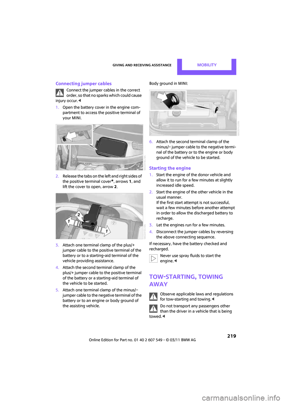
Connecting jumper cables
Connect the jumper cables in the correct
o r d e r , s o t h a t n o s parks which could cause
injury occur. <
1. Open the battery cover in the engine com-
partment to access the positive terminal of
your MINI.
2. Release the tabs on the left and right sides of
the positive terminal cover
*, arrows 1, and
lift the cover to open, arrow 2.
3. Attach one terminal clamp of the plus/+
jumper cable to the positive terminal of the
battery or to a starting-aid terminal of the
vehicle providing assistance.
4. Attach the second terminal clamp of the
plus/+ jumper cable to the positive terminal
of the battery or a starting-aid terminal of
the vehicle to be started.
5. Attach one terminal clamp of the minus/–
jumper cable to the negative terminal of the
battery or to an engine or body ground of
the assisting vehicle. Body ground in MINI:
6.
Attach the second terminal clamp of the
minus/– jumper cable to the negative termi-
nal of the battery or to the engine or body
ground of the vehicle to be started.
Starting the engine
1.Start the engine of the donor vehicle and
allow it to run for a few minutes at slightly
increased idle speed.
2. Start the engine of the other vehicle in the
usual manner.
If the first start attempt is not successful,
wait a few minutes be fore another attempt
in order to allow the discharged battery to
recharge.
3. Let the engines run for a few minutes.
4. Disconnect the jumper cables by reversing
the above connecting sequence.
If necessary, have the battery checked and
recharged. Never use spray fluids to start the
engine. <
Tow-starting, towing
away
Observe applicable laws and regulations
for tow-starting and towing. <
Do not transport an y passengers other
than the driver in a vehicle that is being
towed. <
Page 222 of 254

MOBILITYGiving and receiving assistance
220
Using a tow fitting
The screw-in tow fitting must always be carried
in the car. It can be screwed in at the front or at
the right rear.
The tow fitting can be found under the right
front seat or in the pocket of the tire changing
set
* in the cargo area.
Use only the tow fitting provided with the
vehicle and screw it all the way in. Use the
tow fitting for towing on paved roads only. Avoid
lateral loading of the tow fitting, e.g. do not lift
the vehicle by the tow fitting. Otherwise, the tow
fitting and the vehicle could be damaged. <
Access to screw thread
Press the lower part of the cover. This will push
out the upper edge of the cover, which can then
be removed.
Front
Rear Being towed
Make sure that the igni
tion is switched on,
refer to page 46; otherwise, the low
beams, tail lamps, turn signals, and windshield
wipers may be unavailable. Do not tow the vehi-
cle with just the rear axle raised, as this would
allow the steering to turn. <
There is no power assist while the engine is off.
Thus, braking and steering will require increased
effort.
Switch on the hazard wa rning flashers, depend-
ing on local regulations.
Manual transmission
Gearshift lever in neutral position.
Automatic transmission
Tow vehicles with automatic transmission
only with a tow truck or with the front
wheels lifted; otherwise, the transmission can be
damaged. <
Towing methods
Do not lift vehicle by tow fitting or body
and chassis parts, otherwise damage may
result. <
With towbar
The towing vehicle must not be lighter
than the towed vehicle; otherwise, it may
be impossible to maintain control. <
The tow fittings used should be on the same side
on both vehicles. Should it prove impossible to
avoid mounting the tow bar at an angle, please
observe the following:
> Clearance and maneuver ing capability will
be sharply limited during cornering.
> The tow bar will generate lateral forces if it is
attached offset.
Attach the tow bar to the tow fittings only,
as attaching it to other parts of the vehicle
could result in damage. <
Page 223 of 254
Giving and receiving assistanceMOBILITY
221
With tow rope
When starting off in the towing vehicle, make
sure that the tow rope is taut.To avoid jerking and the associated
stresses on vehicle components when
towing, always use nylon ropes or nylon straps.
Attach the tow rope to the tow fittings only, as
attaching it to other parts of the vehicle could
result in damage. <
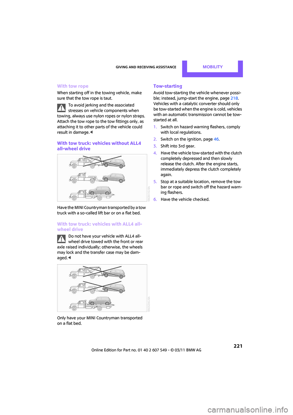
With tow truck: vehicles without ALL4
all-wheel drive
Have the MINI Countryman transported by a tow
truck with a so-called lift bar or on a flat bed.
With tow truck: vehicles with ALL4 all-
wheel drive
Do not have your vehicle with ALL4 all-
wheel drive towed with the front or rear
axle raised individually; otherwise, the wheels
may lock and the transfer case may be dam-
aged. <
Only have your MINI Countryman transported
on a flat bed.
Tow-starting
Avoid tow-starting the vehicle whenever possi-
ble; instead, jump-start the engine, page 218.
Vehicles with a catalytic converter should only
be tow-started when the engine is cold, vehicles
with an automatic transmission cannot be tow-
started at all.
1. Switch on hazard warn ing flashers, comply
with local regulations.
2. Switch on the ignition, page 46.
3. Shift into 3rd gear.
4. Have the vehicle tow-started with the clutch
completely depressed and then slowly
release the clutch. Afte r the engine starts,
immediately depress the clutch completely
again.
5. Stop at a suitable lo cation, remove the tow
bar or rope and switch off the hazard warn-
ing flashers.
6. Have the vehicle checked.
Page 239 of 254
Everything from A to ZREFERENCE
237
B
Background lighting, refer to
Ambient lighting 82
Backrests, refer to Seats 38
Backup lamps
– replacing bulb 211
Band-aids, refer to First aid pouch 218
Bar, refer to Tow-starting,
towing away 220
Base plate for telephone or mobile phone
– refer to Snap-in adapter 174
Bass sounds, refer to Tone control 131
Battery 216
– charging 216
– disposal 34,216
– jump-starting 218
– temporary power failure 216
Battery renewal
– remote control 34
Being towed 220
Belt tensioner, refer to Safety
belts 40
Belts, refer to Safety belts 40
Beverage holders, refer to
Cupholders 92
Black ice, refer to External
temperature warning 56
Blower, refer to Air flow rate 84,86
Bluetooth, activating/ deactivating 154,164
Bluetooth audio 146
– device pairing 146
– disconnecting an audio connection 148
– playback 147
– unpairing device 148
– What to do if... 148
Bottle holders, refer to Cupholders 92
Brake Assist 67
Brake fluid, refer to Service requirements 59 Brake lamps
– replacing bulbs
211
Brake pads, breaking in 96
Brake rotors 97
– brakes 96
– breaking in 96
Brake system 96
– breaking in 96
– disc brakes 97
– MINI Maintenance
System 202
Brakes
– ABS 67
– b
reaking in 96
– MINI Maintenance System 202
– parking brake 47
– service requirements 59
Brakes, refer to Braking
safely 97
Breakdown service, refer to Roadside Assistance 218
Break-in period 96
Breaking in the clutch 96
Brightness of Control
Display 65
Bulb changing, refer to Lamps and bulbs 208
Button for starting the engine 46
Buttons on the steering wheel 11
C
Calendar 179
– displaying appointment 180
– selecting calendar day 180
California Proposition 65
warning 5
Call
– accepting 157,168
– ending 157,168
– muting the microphone 158,170
– rejecting 157,168 Calling, refer to Phone
numbers, dialing 157,169
Can holders, refer to Cupholders 92
Capacities 226
Car battery, refer to Vehicle battery 216
Car care 204
Car key, refer to Keys/remote controls 26
Car phone
– installation location, refer to Center armrest 91
Car phone, refer to Telephone 154,163
Car radio, refer to Radio 132
Car wash
– before driving in 47
Car wash, care 204
Car washes 204
Care 204
– car washes 204
– car-care products 204
– CD/DVD drives 207
– external 204
– high-pressure washers 205
– internal 206
– leather 206
– manual washing 205
– upholstery and fabrics 206
– windows 205
– wiper blades 205
Cargo area 98
– capacity 226
– Comfort Access 33
– lamp 82
– opening from outside 30
– trunk lid, refer to Liftgate 30
Cargo area, expanding 98
Cargo area lamp 82
Cargo area li
d, refer to
Liftgate 30
Cargo area partition net, refer to Cargo net 100