engine MINI Countryman 2011 (Mini Connected) Service Manual
[x] Cancel search | Manufacturer: MINI, Model Year: 2011, Model line: Countryman, Model: MINI Countryman 2011Pages: 254, PDF Size: 3.84 MB
Page 202 of 254
MOBILITYUnder the hood
200
Do not fill beyond the upper mark on the
dipstick. Excess oil will damage the
engine. <
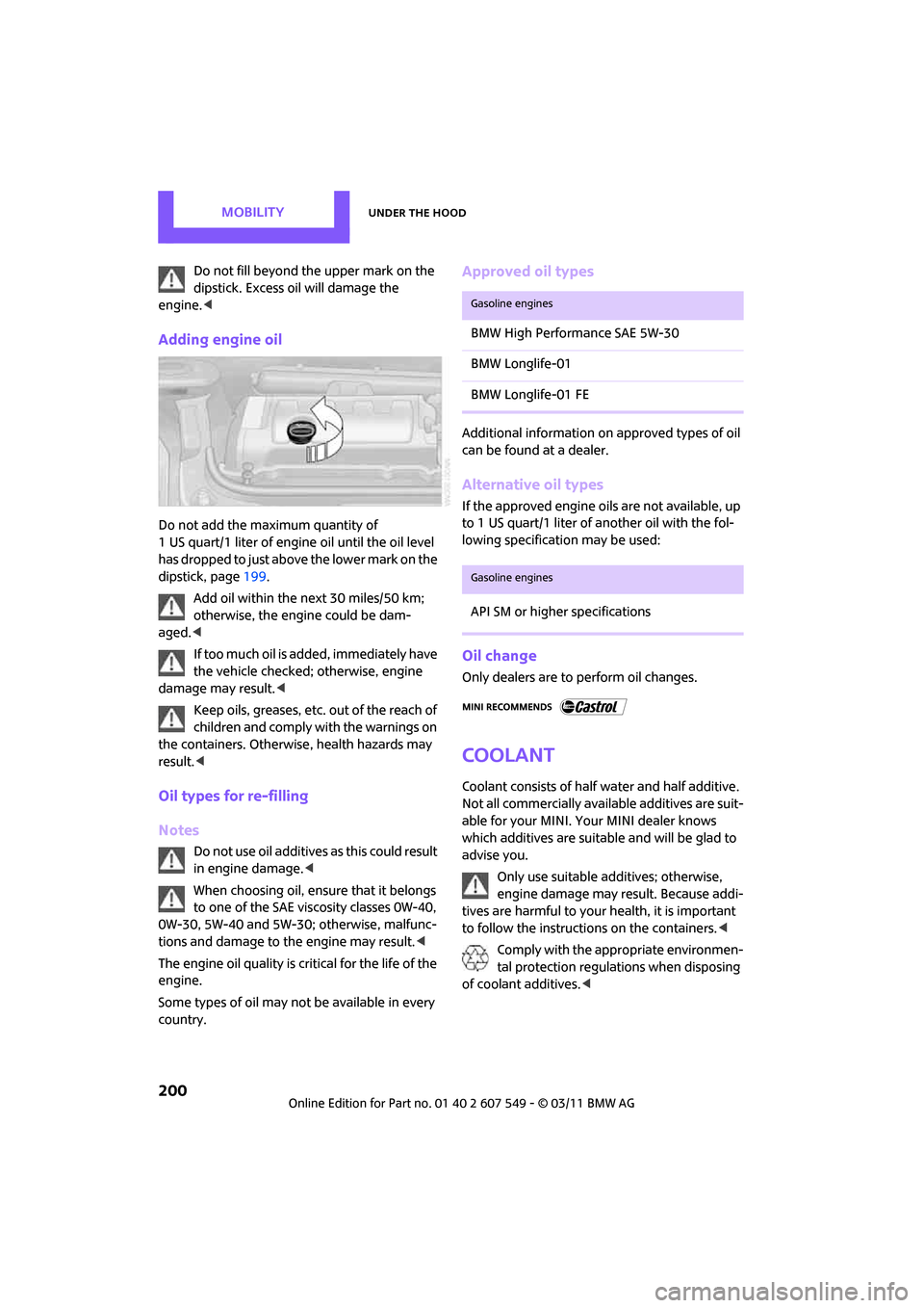
Adding engine oil
Do not add the maximum quantity of
1 US quart/1 liter of engine oil until the oil level
has dropped to just above the lower mark on the
dipstick, page 199.
Add oil within the next 30 miles/50 km;
otherwise, the engine could be dam-
aged. <
If too much oil is added, immediately have
the vehicle checked; otherwise, engine
damage may result. <
Keep oils, greases, etc. out of the reach of
children and comply with the warnings on
the containers. Otherwise, health hazards may
result. <
Oil types for re-filling
Notes
Do not use oil additives as this could result
in engine damage. <
When choosing oil, ensure that it belongs
to one of the SAE viscosity classes 0W-40,
0W-30, 5W-40 and 5W-30; otherwise, malfunc-
tions and damage to the engine may result. <
The engine oil quality is critical for the life of the
engine.
Some types of oil may not be available in every
country.
Approved oil types
Additional information on approved types of oil
can be found at a dealer.
Alternative oil types
If the approved engine oils are not available, up
to 1 US quart/1 liter of another oil with the fol-
lowing specification may be used:
Oil change
Only dealers are to perform oil changes.
Coolant
Coolant consists of half water and half additive.
Not all commercially available additives are suit-
able for your MINI. Your MINI dealer knows
which additives are suitable and will be glad to
advise you.
Only use suitable additives; otherwise,
engine damage may result. Because addi-
tives are harmful to your health, it is important
to follow the instructions on the containers. <
Comply with the appropriate environmen-
tal protection regulations when disposing
of coolant additives. <
Gasoline engines
BMW High Performance SAE 5W-30
BMW Longlife-01
BMW Longlife-01 FE
Gasoline engines
API SM or higher specifications
Page 203 of 254
Under the hoodMOBILITY
201
Coolant temperature
A warning light will come on if the coolant, and
therefore the engine, becomes too hot.
A message appears on the Control Display.
Checking coolant level
Do not add coolant to the cooling system
when the engine is hot. Escaping coolant
can cause burns. <
Do not open the hood until the engine has
cooled down.
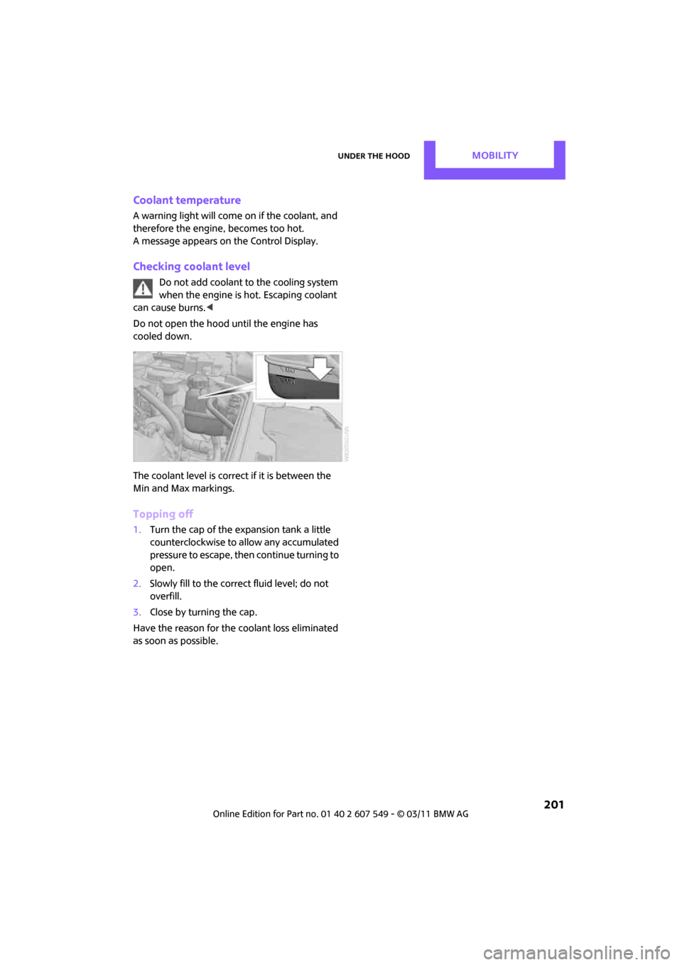
The coolant level is correct if it is between the
Min and Max markings.
Topping off
1. Turn the cap of the expansion tank a little
counterclockwise to allow any accumulated
pressure to escape, then continue turning to
open.
2. Slowly fill to the correct fluid level; do not
overfill.
3. Close by turning the cap.
Have the reason for the coolant loss eliminated
as soon as possible.
Page 205 of 254
MaintenanceMOBILITY
203
Socket for On-Board
Diagnosis OBD
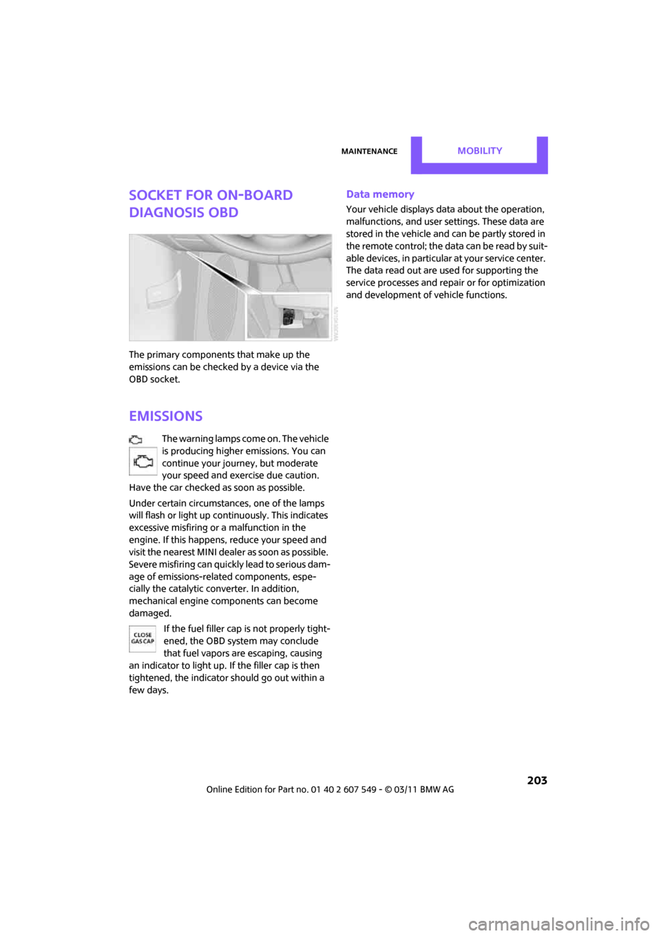
The primary components that make up the
emissions can be checked by a device via the
OBD socket.
Emissions
The warning lamps come on. The vehicle
is producing higher emissions. You can
continue your journey, but moderate
your speed and exercise due caution.
Have the car checked as soon as possible.
Under certain circumstances, one of the lamps
will flash or light up continuously. This indicates
excessive misfiring or a malfunction in the
engine. If this happens, reduce your speed and
visit the nearest MINI dealer as soon as possible.
Severe misfiring can quickly lead to serious dam-
age of emissions-related components, espe-
cially the catalytic converter. In addition,
mechanical engine components can become
damaged.
If the fuel filler cap is not properly tight-
ened, the OBD system may conclude
that fuel vapors are escaping, causing
an indicator to light up. If the filler cap is then
tightened, the indicator should go out within a
few days.
Data memory
Your vehicle displays data about the operation,
malfunctions, and user settings. These data are
stored in the vehicle and can be partly stored in
the remote control; the da ta can be read b y su it-
able devices, in particular at your service center.
The data read out are used for supporting the
service processes and repair or for optimization
and development of vehicle functions.
Page 206 of 254
MOBILITYCare
204
Care
Car-care products
Regular cleaning and care helps to maintain the
value of your MINI.
The manufacturer of your MINI recommends
using manufacturer-approved products to clean
and care for your vehicle.
Your MINI dealer would be pleased to advise
you on cleaning and care products and services
for your MINI.The ingredients of original MINI Care Prod-
ucts have been tested, and the products
have been tested in the laboratory and in prac-
tice. They offer optimum care and protection for
your vehicle. <
Do not use any cleansers containing alco-
hol or solvents as these may cause dam-
age. <
Cleaning agents may contain hazardous
or health-damaging substances. Follow
the warning and hazard instructions on the
packaging. For interior cleaning, always open
the doors or windows of the vehicle.
Do not use any products that are not intended
for cleaning the vehicle. <
External care
Washing your vehicle
Especially during the winter months the
vehicle should be frequently washed. Dirt
and road salt can damage the vehicle. <
After washing the vehicle, apply the
brakes briefly to dry them; otherwise,
water can reduce braking efficiency over the
short term and the brake rotors can corrode. <
Car washes
Preference should be given to cloth car washes.
Do not use automatic high-pressure car
washes; otherwise, water may drip into
the vehicle around the windows. <
Before driving in to the car wash, check if the sys-
tem is suitable for your MINI. Observe the fol-
lowing points:
> Vehicle dimensions, page 225
> If necessary: fold in the outside mirrors,
page 41
> Maximum permissible tire width
Avoid car washes with tracks higher than
4 in/10 cm; otherwise, the chassis could
be damaged. <
Preparations for driving into the car wash:
> Unscrew the rod antenna.
> Deactivate the rain sensor
* to prevent unin-
tentional wiping.
> Deactivate rear window wiper and protect it
from damage. Ask the car wash operator
about measures that can be taken to protect
the wipers.
> Remove additional atta chments, e.g. spoil-
ers or telephone antennas, if there is a pos-
sibility that they could be damaged.
> Inserting the remote control into the ignition
lock.
Automatic transmission
Before driving into the car wash, make sure that
the vehicle can roll:
1.Place the remote control, even with Comfort
Access, in the ignition lock.
2. Move the selector le ver to position N.
3. Release the parking brake.
4. Switch off the engine.
Page 211 of 254
Replacing componentsMOBILITY
209
tional laser diodes, and legislation defines them
as Class 1 light-emitting diodes.
Do not remove the covers or expose the
eyes directly to the unfiltered light source
for several hours; otherw ise, this could cause
irritation of the retina. <
Headlamp glass lens
In cool or humid weather, condensation may
occur on the interior of outside lights. The con-
densation disappears a short time after the light
is switched on. The headlamps do not need to
be changed. If a lot of moisture is present, e.g.
water droplets in the light, have them checked
by your service center.
Xenon lamps*
The service life of these bulbs is very long and
the probability of failure very low, provided that
they are not switched on and off an excessive
number of times. If a xenon lamp fails neverthe-
less, switch on the fog lamps and continue the
journey with great care, provided that local leg-
islation does not prohibit this.
Have any work on the xenon lamp system,
including bulb replac ement, carried out
only by a MINI dealer or a workshop that has
specially trained personnel working in accor-
dance with the specifications of the MINI manu-
facturer. Due to high voltage, there is a risk of
fatal injury if work on the xenon lamps is carried
out improperly. <
Halogen low beams and high beams
H13 bulb, 60/55 watts
The H13 bulb is pressurized. Therefore,
wear safety glasses an d protective gloves.
Otherwise, there is a risk of injury if the bulb is
damaged. <
Be careful when insta lling the cover; oth-
erwise, leaks could occur and cause dam-
age to the headlamp system. <
Accessing the lamp from the engine
compartment
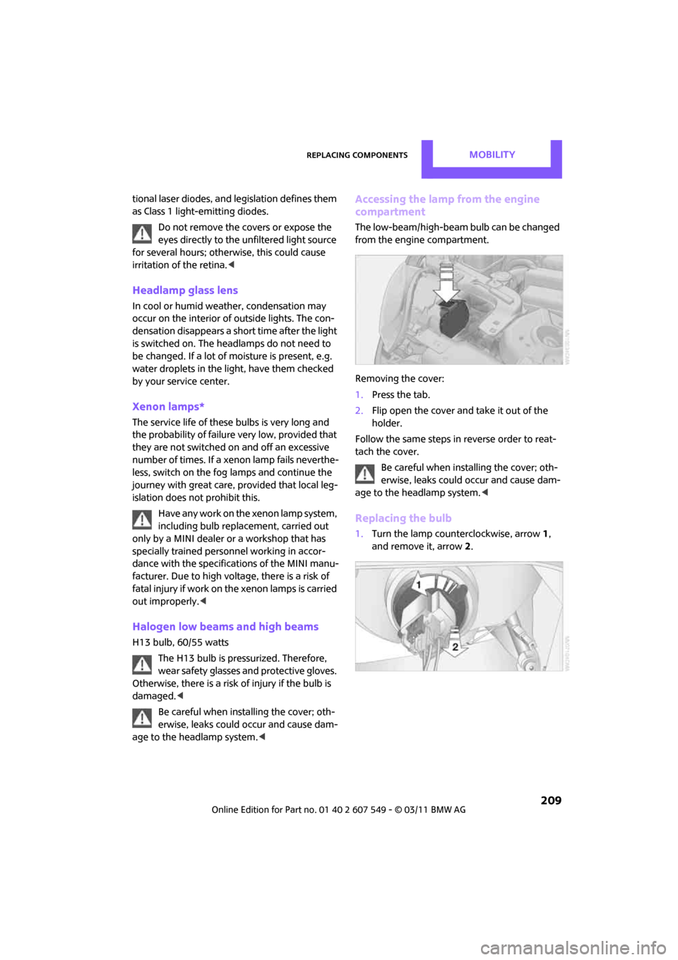
The low-beam/high-beam bulb can be changed
from the engine compartment.
Removing the cover:
1.Press the tab.
2. Flip open the cover and take it out of the
holder.
Follow the same steps in reverse order to reat-
tach the cover. Be careful when insta lling the cover; oth-
erwise, leaks could occur and cause dam-
age to the headlamp system. <
Replacing the bulb
1.Turn the lamp counterclockwise, arrow 1,
and remove it, arrow 2.
Page 215 of 254

Replacing componentsMOBILITY
213
Sealant and compressor
1Sealant bottle and adhesi ve label with speed
limit
2 Filling hose
Note the use-by date on the sealant bot-
tle. <
3 Holder for the sealant bottle
4 Compressor
5 Plug and cable for the socket in the vehicle
interior, page 92
6 Connection hose to connect the compressor
and sealant bottle or the compressor and
wheel
7 On/off switch
8 Pressure gauge for indi cating the tire infla-
tion pressure
9 Release button for reduci ng the tire inflation
pressure
Connector, cable and connection hose are
stored in the compressor housing.
Using the Mobility System
To repair a tire puncture with the Mobility Sys-
tem, proceed as follows: >
Filling the tire with sealant
> Distributing the sealant
> Correct the tire inflation pressure
Filling the tire with sealant
Proceed in the specified order; otherwise,
sealant may emerge under high pres-
sure. <
1. Shake the sealant bottle.
2. Pull the connecting hose 6 completely out of
the compressor housing and screw it onto
the connector of the sealant bottle. Make
sure that the hose is not kinked.
3. Insert the sealant bottle on the compressor
housing in an upright position.
4. Unscrew the dust cap from the valve of the
defective wheel and screw the filling hose 2
of the sealant bottle onto the valve.
5. Ensure that the compressor is switched off.
6. Insert the plug 5 into the lighter socket/
power socket in the vehicle interior,
page 92.
7. With the engine running:
Switch on the compresso r and let it run for
approx. 3 to 8 minutes to fill the tire with
sealant and achieve a ti re inflation pressure
of approx. 26 psi/180 kPa.
When filling with the sealant, the infla-
tion pressure can briefly rise to
approx. 73 psi/500 kPa. Do not switch off
the compressor during this phase. <
Do not run the compressor for longer
than 10 minutes; otherwise, the
Page 216 of 254

MOBILITYReplacing components
214
device will overheat and possibly be dam-
aged.<
8. Switch off the compressor.
If an air pressure of 26 psi/180 kPa is not
reached:
1. Unscrew the filling hose 2 from the wheel
and drive the vehicle forward and backward
approx. 33 ft/10 m to distribute the liquid
sealant in the tire evenly.
2. Inflate the tire again with the compressor.
If an inflation pressure of 26 psi/180 kPa
still cannot be reache d, the tire is too
heavily damaged. Please contact the nearest
MINI dealer. <
Stowing Mobility System
1.Unscrew filler hose 2 of the sealant bottle
from the wheel.
2. Unscrew connecting hose of the
compressor 6 from the sealant bottle.
3. Connect the filler hose 2 of the sealant bot-
tle to the unoccupied connection on the
sealant bottle.
This prevents the rest of the sealant from
escaping from the bottle.
4. Wrap the empty sealant bottle in suitable
material to avoid dirt ying the cargo area.
5. Stow Mobility System back in the vehicle.
Distributing the sealant
Immediately drive approx. 3 miles/5 km so that
the sealant evenly distributes itself.
Do not exceed speeds of 50 mph/
80 km/h.
If possible, do not drop below 10 mph/
20 km/h. <
Correct the tire inflation pressure
1.After driving approx. 3 miles/5 km or ten
minutes, stop at a suitable location.
2. Screw the connection hose 6 of the com-
pressor directly onto the tire valve. 3.
Insert the plug 5 into the power socket in
the vehicle interior.
4. Correct inflation pressu re to 26 psi/180 kPa.
With the engine running:
> To increase the inflatio n pressure: switch on
the compressor. To ch eck the current infla-
tion pressure, switch off the compressor.
Do not run the compressor for longer
than 10 minutes; otherwise, the
device will overheat and possibly be dam-
aged.<
> To decrease the inflat ion pressure: press the
release button 9.
If the tire cannot m aintain the inflation
pressure, drive the vehicle again, refer to
Distributing the sealan t. Then repeat steps
1to4.
If an inflation pressure of 26 psi/180 kPa still
cannot be reached, the tire is too heavily dam-
aged. Contact the nearest MINI dealer. <
Driving on
Do not exceed the permitted maximum
speed of 50 mph/80 km/h; doing so may
result in an accident. <
Replace the defective tire as soon as possible
and have the new wheel/tire assembly bal-
anced.
Have the Mobility System refilled.
Changing wheels
The pouch with the wheel changing kit* is
stored under the flat load floor
*. It includes:
> Vehicle jack
> Reversible ratchet
> Wheel stud wrench
> Extractor hook for wheel center cover
> Chock
Page 217 of 254

Replacing componentsMOBILITY
215
Preparing for a wheel change
Observe the safety precautions regarding
flat tires on page212.<
Additional safety measures when chang-
ing tires:
Only change the tire when parked on a surface
that is level, firm and not slippery.
The vehicle or the jack could slip sideways on
soft or slippery support surfaces, such as snow,
ice, flagstones, etc.
Do not use a wooden block or similar object as a
support base for the jack, as this would prevent
it from extending to its full support height and
reduce its load-carrying capacity.
Do not lie under the vehicle or start the engine
when the vehicle is supported by the jack; other-
wise, there is a risk of fatal injury. <
1. Place the foldable chock
* behind the front
wheel on the other side of the vehicle or in
front of the wheel if the vehicle is on an
incline. If the wheel is changed on a surface
with a more severe slope, take additional
precautions to secure the vehicle from roll-
ing.
2. Uncover the lug bolts if necessary.
3. Loosen the lug bolts by a half turn.
Jacking up the vehicle
The vehicle jack is designed for changing
wheels only. Do not attempt to raise
another vehicle model with it or to raise any load
of any kind. To do so could cause accidents and
personal injury. <
1. Place the jack at the jacking point closest to
the wheel. The jack base must be perpendicular to the
surface beneath the jacking point.
2. Slide reversible ratchet onto the fixture on
the jack, arrow 1.
3. As you ratchet up the jack, place the jack
head onto the lifting point on the body,
arrow 2.
4. Jack the vehicle up until the wheel you are
changing is raised off the ground.Mounting the wheel
1.Unscrew the lug bolts and remove the
wheel.
2. Remove accumulations of mud or dirt from
the mounting surfaces of the wheel and
hub. Clean the lug bolts.
3. Lift the new wheel into place.
4. Screw at least two lug bo lts finger-tight into
opposite bolt holes.
5. Screw in the remaining bolts.
6. Tighten all the lug bolts firmly in a diagonal
pattern.
7. Lower the vehicle.
8. Remove the jack.
Page 218 of 254
MOBILITYReplacing components
216
Tightening the lug bolts
Tighten the lug bolts in a diagonal pattern.
Immediately have the wheels checked
with a calibrated torque wrench to ensure
that the lug bolts are firmly seated. Otherwise,
incorrectly tightened lu g bolts can present a
safety hazard. <
Tightening torque: 103.3 lb ft or 140 Nm.
Replace the defective tire as soon as possible
and have the new wheel/tire assembly bal-
anced.
Vehicle battery
Maintenance
The battery is 100 % maintenance-free, the
electrolyte will last for the life of the battery
when the vehicle is operated in a temperate cli-
mate.
Battery replacement
Only use vehicle batteries that have been
approved for your vehicle by the manu-
facturer; otherwise, the vehicle could be dam-
aged and systems or func tions may not be fully
available. <
After a battery replacement, have the battery
registered on the vehicle by your dealer to
ensure that all comfort functions are fully avail-
able.
Charging the battery
Only charge the battery in the vehicle when the
engine is off. Connectio ns, refer to Jump-start-
ing on page 218.
Disposal
After replacing old ba tteries, return the
used batteries to your MINI dealer or to a
recycling center. Maintain the battery in an
upright position for transport and storage.
Always secure the battery against tipping over
during transport. <
Power failure
After a temporary power loss, some equipment
may not be fully functional and may require ini-
tialization. Individual se ttings are also lost and
must be reprogrammed:
> Time and date
These values must be updated, page 61.
> Radio
In some cases, stations may have to be
stored again, page 132.
> Navigation system
Operability must be waited for, page108.
> Glass sunroof
*, electric
It may only be possible to tilt the sunroof, if
applicable. The system must be initialized.
Contact your near est MINI dealer.
Fuses
Do not attempt to repair a blown fuse or
replace it with a fuse of a different color or
Ampere rating. To do this could cause a fire in
the vehicle resulting from a circuit overload.
Have the fuse changed only by a MINI dealer or
a workshop that has specially trained personnel
working in accordance with the specifications of
the MINI manufacturer. <
A fuse allocation diagram is located on the inside
of the fuse box cover panels.
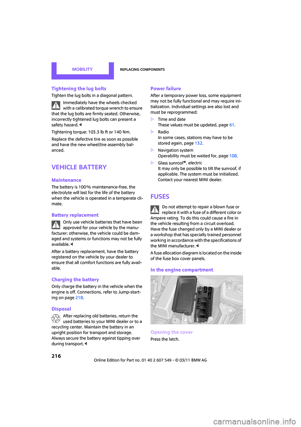
In the engine compartment
Opening the cover
Press the latch.
Page 220 of 254

MOBILITYGiving and receiving assistance
218
Giving and receiving assistance
Roadside Assistance
Roadside Assistance is available by phone
24 hours a day in many countries. You can
obtain assistance there in the event of a vehicle
breakdown.
First aid pouch*
Some of the articles co ntained in the first aid
pouch have a limited service life. Therefore,
check the expiration dates of the contents regu-
larly and replace any item s in good time, if nec-
essary.
The first aid pouch is located on the rear cargo
well by the left side trim panel or under the pull-
out floor panel.
Warning triangle*
In the cargo area under the loading sill.
To remove, open the two clasps.
Jump-starting
If the car's own battery is flat, your MINI's engine
can be started by connecting two jumper cables
to another vehicle's battery. You can also use
the same method to help start another vehicle.
Only use jumper cables with fully-insulated
clamp handles.
Do not touch any electrically live parts
wh en t he e ngine is run nin g, or a fatal acci-
dent may occur. Carefully adhere to the follow-
ing sequence, both to prevent damage to one or
both vehicles, and to guard against possible per-
sonal injuries. <
Preparation
1.Check whether the battery of the other vehi-
cle has a voltage of 12 volts and approxi-
mately the same capa citance in Ah. This
information can be found on the battery.
2. Switch off the engine of the support vehicle.
3. Switch off any consumers in both vehicles.
There must not be any contact between
the bodies of the two vehicles; otherwise,
there is a danger of shorting. <