ECU MINI Countryman 2012 Owner's Manual (Mini Connected)
[x] Cancel search | Manufacturer: MINI, Model Year: 2012, Model line: Countryman, Model: MINI Countryman 2012Pages: 259, PDF Size: 3.07 MB
Page 23 of 259
AT A GLANCEVoice activation system
22
Terminating or canceling voice
activation system
Press the button on the steering wheel
or
Commands
Individual menu items on the Control Display
can be voiced as commands.
The commands that are possible depend upon
which menu is currently shown on the Control
Display.
There are short commands for functions in the
main menu.
Some list items, for example telephone book
listings, can also be selected using the voice acti-
vation system. In particular, say the list items
exactly as they are displayed in the respective
list.
Having the possible commands read
aloud
Having the possible co mmands read aloud:
For example if you have selected "CD" the sys-
tem will read aloud the possible commands for
operating the CD player.
Help for the voice activation system
Calling up Help:
Additional commands for Help:
> {Help with examples }: information about
the current operating options and the most
important commands for them are
announced.
> {Help with voice activation }: information
regarding the principles behind the voice
activation system is announced.
Using alternative commands
There are often a number of commands to run a
function, e.g.:
Carrying out functions through short
commands
Main menu functions can be executed
immediately by short commands, almost
regardless of which menu item is selected, e.g.,
{ Vehicle status }.
List of voice activation system short commands,
see page 236.
Opening the main menu
Example: selecting the track of a CD
1.Switch on Entertainment sound output if
necessary.
2. Press the button on the steering wheel.
Setting the voice dialog
You can set whether the voice activation system
uses the standard dialog or the short version.
With the short version of the spoken dialog, the
requests and responses of the voice activation
system are shortened.
1."Settings"
2. "Language/Units"
{
Cancel}
{ Voice commands }
{ Help }
{Radio } or {Radio on }
{ Main menu }
3. Select the music track, e.g.:
{C D track … }
The system replies:
{{ Track … }}
Online Edition for Part no. 01 40 2 914 849 - \251 07/12 BMW AG
Page 46 of 259
Transporting children safelyCONTROLS
45
Child seat security
All rear safety belts and the safety belt for the
front passenger can be prevented from being
pulled out in order to secure child restraint
systems.
Locking the safety belt
1.Secure the child restraint system with the
belt.
2. Pull the belt strap all the way out.
3. Allow the belt strap to retract and pull it taut
against the child restraint system.
The safety belt is locked.
Unlocking the safety belt
1. Open the belt buckle.
2. Remove the child restraint system.
3. Allow the safety belt strap to retract all the
way.
Center belt: unlocking additional belt buckle
3, see page 41.
Guide safety belt to the take-up on the
headliner.
LATCH child restraint
fixing system
LATCH: Lower Anchors an d Tethers for Children.
To install and use the LATCH child restraint
system, follow the op erating and safety
instructions provided by the manufacturer of the
system; otherwise, the protective function of the
seat may be compromised. <
Anchor points for LATCH anchors
Before installing the child seat, pull the belt out
of the area for the child restraint fixing system.
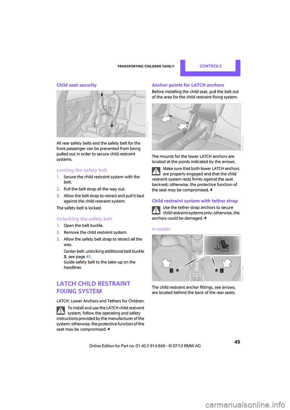
The mounts for the lower LATCH anchors are
located at the points indicated by the arrows.
Make sure that both lower LATCH anchors
are properly engaged and that the child
restraint system rests fi rmly against the seat
backrest; otherwise, the protective function of
the seat may be compromised. <
Child restraint system with tether strap
Use the tether strap anchors to secure
child restraint systems only; otherwise, the
anchors could be damaged. <
4-seater
The child restraint anchor fittings, see arrows,
are located behind the back of the rear seats.
Online Edition for Part no. 01 40 2 914 849 - \251 07/12 BMW AG
Page 47 of 259
CONTROLSTransporting children safely
46
5-seater
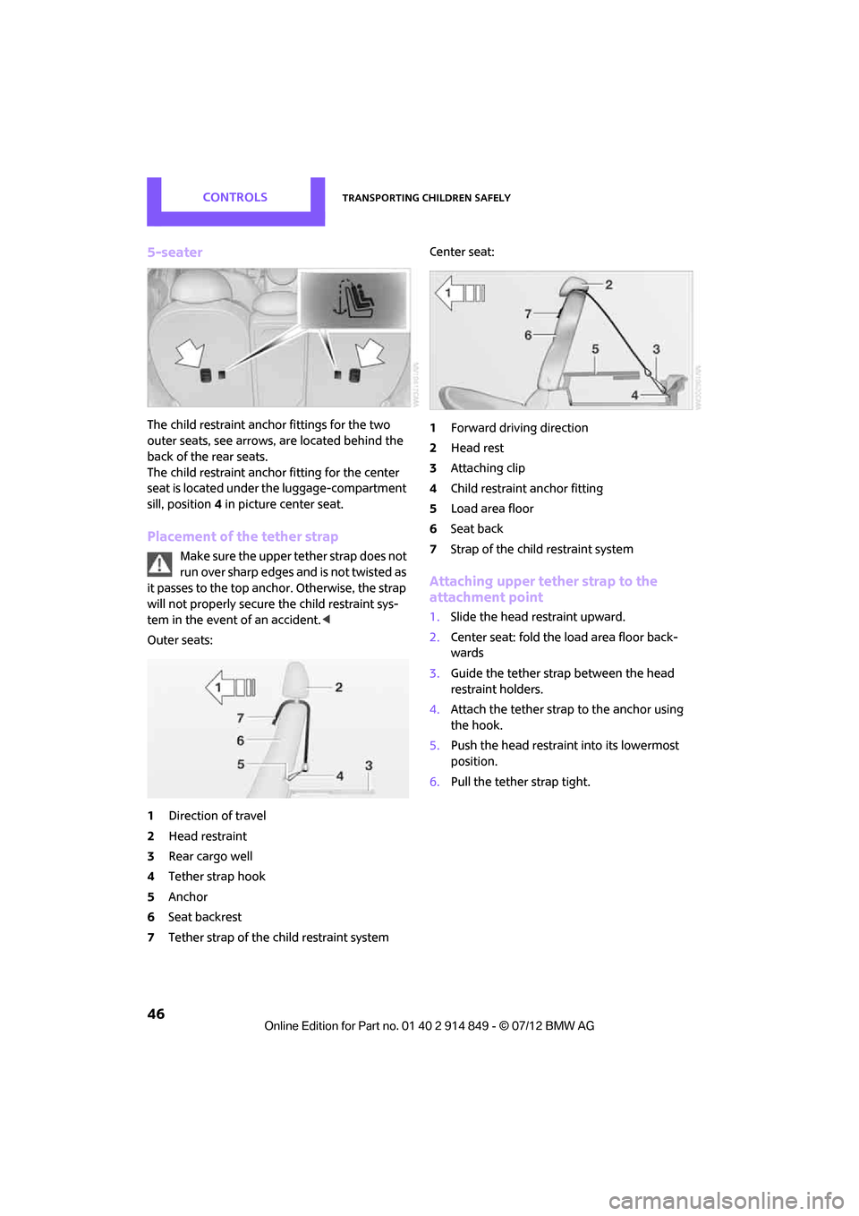
The child restraint anchor fittings for the two
outer seats, see arrows, are located behind the
back of the rear seats.
The child restraint anchor fitting for the center
seat is located under the luggage-compartment
sill, position4 in picture center seat.
Placement of the tether strap
Make sure the upper tether strap does not
run over sharp edges and is not twisted as
it passes to the top anchor. Otherwise, the strap
will not properly secure the child restraint sys-
tem in the event of an accident. <
Outer seats:
1 Direction of travel
2 Head restraint
3 Rear cargo well
4 Tether strap hook
5 Anchor
6 Seat backrest
7 Tether strap of the child restraint system Center seat:
1
Forward driving direction
2 Head rest
3 Attaching clip
4 Child restraint anchor fitting
5 Load area floor
6 Seat back
7 Strap of the chil d restraint system
Attaching upper tether strap to the
attachment point
1.Slide the head restraint upward.
2. Center seat: fold the load area floor back-
wards
3. Guide the tether strap between the head
restraint holders.
4. Attach the tether strap to the anchor using
the hook.
5. Push the head restraint into its lowermost
position.
6. Pull the tether strap tight.
Online Edition for Part no. 01 40 2 914 849 - \251 07/12 BMW AG
Page 48 of 259
Transporting children safelyCONTROLS
47
Securing doors and
windows
Rear doors
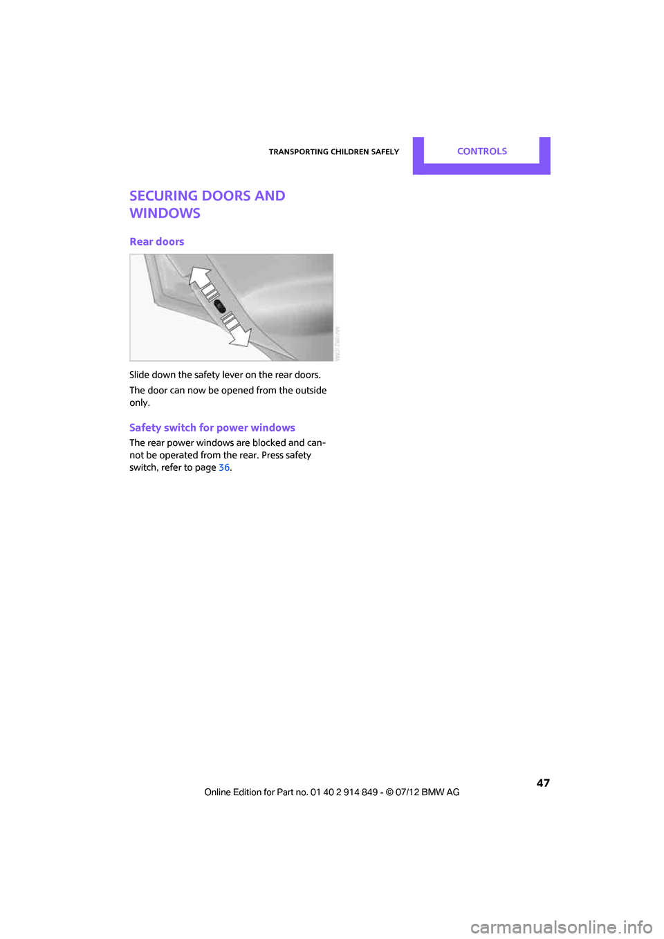
Slide down the safety lever on the rear doors.
The door can now be opened from the outside
only.
Safety switch for power windows
The rear power windows are blocked and can-
not be operated from the rear. Press safety
switch, refer to page36.
Online Edition for Part no. 01 40 2 914 849 - \251 07/12 BMW AG
Page 50 of 259
DrivingCONTROLS
49
Radio readiness and ignition off
All indicator and warning lamps in the displays
go out.
The ignition switches off automatically if the
driver's door is opened. Pressing the Start/Stop
button again switches the ignition back on.
The ignition is not switched off in situations such
as the following:
>The clutch or brake is depressed
> The low beams are switched on
Starting the engine
Do not allow the engine to run in enclosed
areas; otherwise, inhalation of the noxious
exhaust gases can lead to loss of consciousness
and death. Exhaust gases contain carbon mon-
oxide, an odorless and colorless, but highly toxic
gas. Never leave an unattended vehicle with the
engine running; otherwise, such a vehicle repre-
sents a potential safety hazard.
Before leaving the car while the engine is run-
ning, place the transmission in neutral or move
the selector lever to position P and forcefully
apply the parking brake to prevent the car from
moving. <
Avoid frequent starting in quick succes-
sion or repeated start attempts in which
the engine does not start. Otherwise, the fuel is
not burned or inadequately burned and there is
a danger of overheating and damaging the
catalytic converter. <
Do not let the engine warm up with the vehicle
at a standstill. Move of f immediately at a moder-
ate engine speed.
When starting the engine, do not depress the
accelerator pedal.
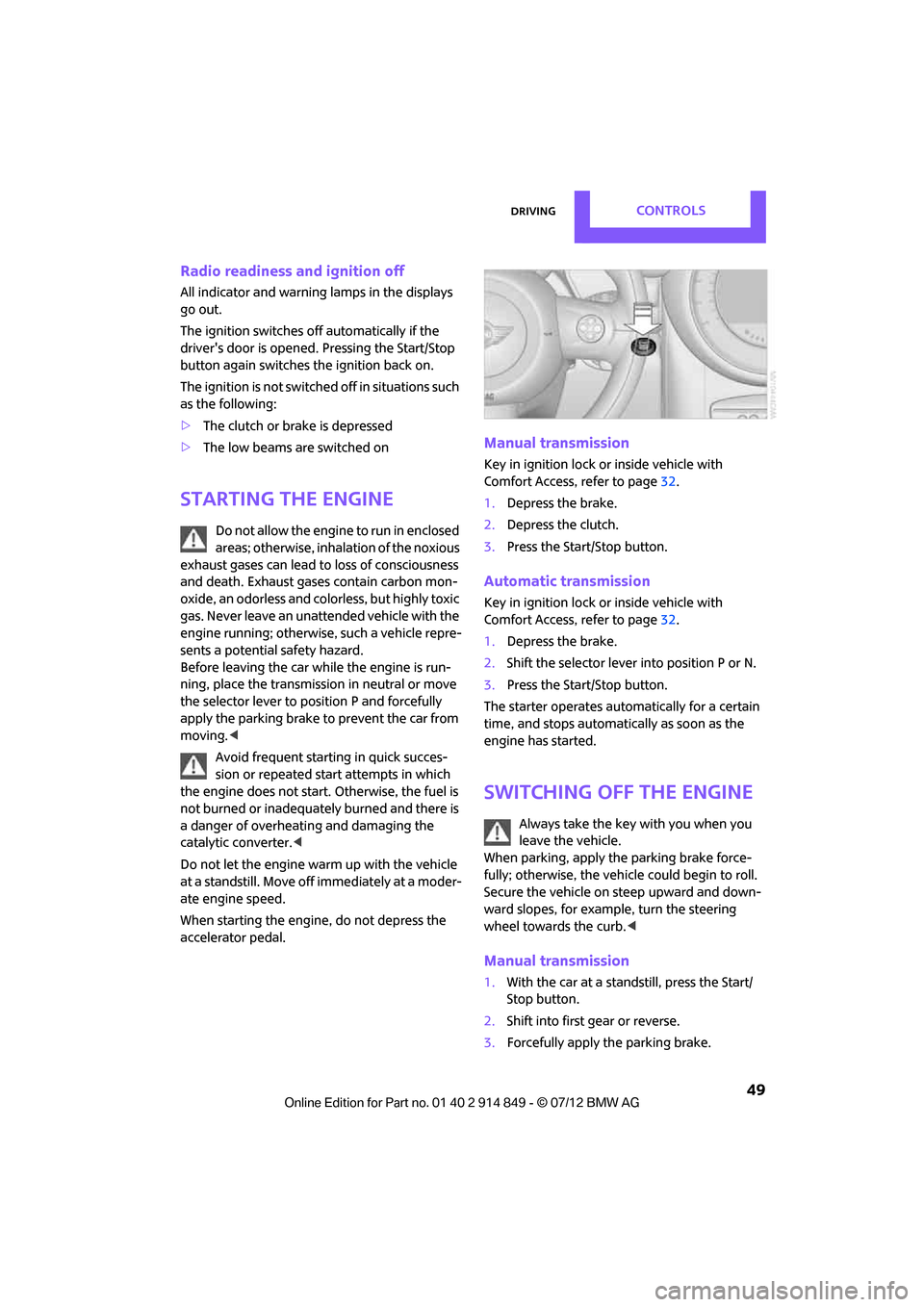
Manual transmission
Key in ignition lock or inside vehicle with
Comfort Access, refer to page 32.
1. Depress the brake.
2. Depress the clutch.
3. Press the Start/Stop button.
Automatic transmission
Key in ignition lock or inside vehicle with
Comfort Access, refer to page 32.
1. Depress the brake.
2. Shift the selector lever into position P or N.
3. Press the Start/Stop button.
The starter operates auto matically for a certain
time, and stops automatically as soon as the
engine has started.
Switching off the engine
Always take the key with you when you
leave the vehicle.
When parking, apply the parking brake force-
fully; otherwise, the vehicle could begin to roll.
Secure the vehicle on steep upward and down-
ward slopes, for example, turn the steering
wheel towards the curb. <
Manual transmission
1.With the car at a standstill, press the Start/
Stop button.
2. Shift into first gear or reverse.
3. Forcefully apply the parking brake.
Online Edition for Part no. 01 40 2 914 849 - \251 07/12 BMW AG
Page 53 of 259
CONTROLSDriving
52
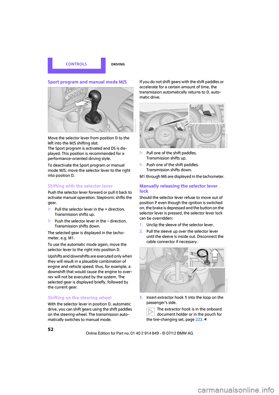
Sport program and manual mode M/S
Move the selector lever from position D to the
left into the M/S shifting slot:
The Sport program is activated and DS is dis-
played. This position is recommended for a
performance-oriented driving style.
To deactivate the Sport program or manual
mode M/S, move the selector lever to the right
into position D.
Shifting with the selector lever
Push the selector lever forward or pull it back to
activate manual operation. Steptronic shifts the
gear.
> Pull the selector lever in the + direction.
Transmission shifts up.
> Push the selector leve r in the – direction.
Transmission shifts down.
The selected gear is displayed in the tacho-
meter, e.g. M1.
To use the automatic mode again, move the
selector lever to the right into position D.
Upshifts and downshifts are executed only when
they will result in a plausible combination of
engine and vehicle speed; thus, for example, a
downshift that would cause the engine to over-
rev will not be executed by the system. The
selected gear is displayed briefly, followed by
the current gear.
Shifting on the steering wheel
With the selector lever in position D, automatic
drive, you can shift gears using the shift paddles
on the steering wheel. The transmission auto-
matically switches to manual mode. If you do not shift gears with the shift paddles or
accelerate for a certai
n amount of time, the
transmission automatically returns to D, auto-
matic drive.
> Pull one of the shift paddles.
Transmission shifts up.
> Push one of the shift paddles.
Transmission shifts down.
M1 through M6 are displayed in the tachometer.
Manually releasing the selector lever
lock
Should the selector lever refuse to move out of
position P even though the ignition is switched
on, the brake is depressed and the button on the
selector lever is pressed, the selector lever lock
can be overridden:
1. Unclip the sleeve of the selector lever.
2. Pull the sleeve up over the selector lever
until the sleeve is insi de out. Disconnect the
cable connector if necessary.
3. Insert extractor hook 1 into the loop on the
passenger's side.
The extractor hook is in the onboard
document holder or in the pouch for
the tire-changing set, page 222.<
Online Edition for Part no. 01 40 2 914 849 - \251 07/12 BMW AG
Page 71 of 259
CONTROLSTechnology for driving comfort and safety
70
enter the sensors' blind spots before or after a
continuous audible signal is given. Higher, pro-
truding objects, such as wall ledges, may not be
detectable. Therefore, always drive cautiously;
otherwise, there is a risk of personal injury or
property damage. Loud sound sources outside
or inside the car can drown out the PDC signal. <
Driving stability control
systems
Your MINI has a number of systems that help to
maintain the vehicle's stability even in adverse
driving conditions.
The laws of physics cannot be repealed,
even with driving stability control systems.
An appropriate driving style always remains the
responsibility of the driver. Therefore do not
reduce the additional safe t y m a r g i n b y e n g a g i n g
in hazardous driving thereby running the risk of
an accident. <
Antilock Brake System ABS
ABS prevents locking of the wheels during brak-
ing. Safe steering response is maintained even
during full braking. Active safety is thus
increased.
Braking safely, refer to page 103.
ABS is operational every time you start the
engine.
Cornering Brake Control CBC
Driving stability and stee ring characteristics are
further enhanced while braking in turns or
during a lane change.
Electronic brake-force distribution EBV
The system controls the brake pressure in the
rear wheels to ensure stable braking behavior.
Brake Assist
Rapidly depressing the brake causes this system
to automatically develop maximum braking force. Thus, the system helps keep braking dis-
tance to a minimum. At the same time, all the
benefits provided by ABS are exploited.
Do not reduce the pressure on the brake for the
duration of the full braking application.
Dynamic Stability Control DSC
The concept
DSC prevents the driving wheels from losing
traction when you pull away from rest or
accelerate.
DSC also detect
s unstable driving conditions
such as when the vehicle's rear end fishtails or
the vehicle is sliding on its front wheels. In these
cases, DSC helps the ve hicle maintain a safe
course within physical limits by reducing engine
output and through braking actions at the indi-
vidual wheels.
Every time that the engine is started, DSC is
ready to operate.
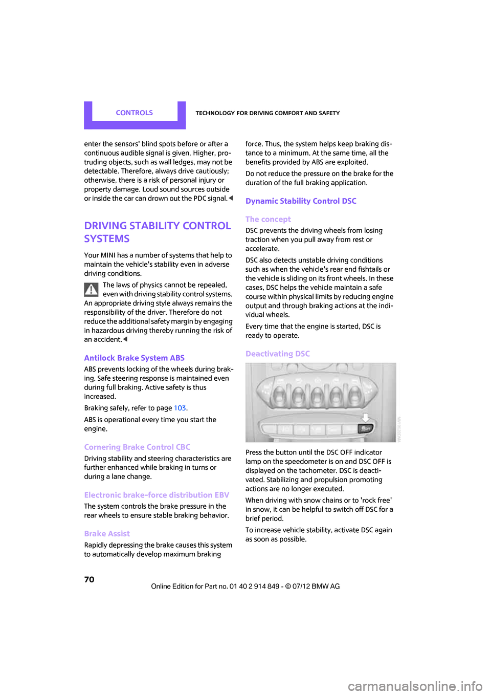
Deactivating DSC
Press the button until the DSC OFF indicator
lamp on the speedometer is on and DSC OFF is
displayed on the tachometer. DSC is deacti-
vated. Stabilizing and propulsion promoting
actions are no longer executed.
When driving with snow chains or to 'rock free'
in snow, it can be helpfu l to switch off DSC for a
brief period.
To increase vehicle stabil ity, activate DSC again
as soon as possible.
Online Edition for Part no. 01 40 2 914 849 - \251 07/12 BMW AG
Page 80 of 259
Technology for driving comfort and safetyCONTROLS
79
Protective action
Observe the instructions on page37 to
ensure the best possible personal protec-
tion. <
The front airbags help protect the driver and
front passenger by responding to frontal
impacts in which safety belts alone cannot pro-
vide adequate restraint. When needed, the head
and side airbags help provide protection in the
event of side impact. Th e relevant side airbag
supports the side upper body area. The head air
bag supports the head.
The airbags are designed to not be triggered in
every type of collision, e.g. not in minor acci-
dents, certain rollover si tuations or rear impacts.
Do not apply adhesive materials to the
cover panels of the airbags, cover them or
modify them in any other way.
Keep the dashboard and window on the passen-
g e r s i d e f r e e f r o m o b s t r u c t i o n , i . e . d o n o t c o v e r i t
with adhesive film or coverings, and do not affix
any holders such as for a navigation device or a
mobile phone.
Do not attach seat covers, cushions or other
objects not specifically approved for seats with
integral side airbags to the front seats. Do not
hang items of clothing such as coats or jackets
over the backrests. Do not attempt to remove
the airbag retention system from the vehicle. Do
not modify the individual components of the
system or its wiring in any way. This includes the
upholstery in the center of the steering wheel,
on the instrument panel, the doors, and the roof
pillars as well as the side s of the headliner. Do
not attempt to remove or dismantle the steering
wheel. <
Do not touch the individual components
immediately after the system has been
triggered, because there is a danger of burns.
Have the testing, repair , removal, and disposal
of airbag generators executed only by your MINI
dealer or a workshop that has the required
explosives licenses.
Otherwise, unprofessional attempts to service
the system could lead to failure in an emergency or undesired airbag activation, either of which
could result in personal injury.
<
Warning notices and in formation about the
airbags can also be found on the sun visors.
Automatic deactivation of the front
passenger airbags
The presence of a passenger in the front passen-
ger seat is detected by measuring the resistance
of the human body. The system correspondingly
activates or deactivates the front, side, and knee
airbags for the front passenger.
Make sure that the front passenger's feet
remain in the footwell; otherwise, it is not
possible to guarantee the function of the front
passenger airbags. <
The indicator lamp above the interior rearview
mirror shows the current st atus of the front pas-
senger airbags, deactivate d or activated, refer to
Status of front passenger airbags below.
Before transporting a child on the front
passenger seat, read the safety informa-
tion and follow the instructions under Transport-
ing children safely, page 44.<
Malfunction of the automatic
deactivation
When teenagers and adul ts assume certain sit-
ting positions, this can cause the front, side, and
knee airbags to deactivate. The indicator lamp
for the front passenger airbags lights up when
this occurs. In such case s, the passenger should
change his or her sittin g position so that the
front passenger airbags are activated and the
indicator lamp goes out. If the desired airbag
status cannot be achieved by changing the sit-
ting position, transport the relevant passenger
on a rear seat.
> Do not attach covers, cushions, ball mats or
other items to the front passenger seat
unless they are specifically recommended
by the manufacturer of your MINI.
Online Edition for Part no. 01 40 2 914 849 - \251 07/12 BMW AG
Page 96 of 259
Practical interior accessoriesCONTROLS
95
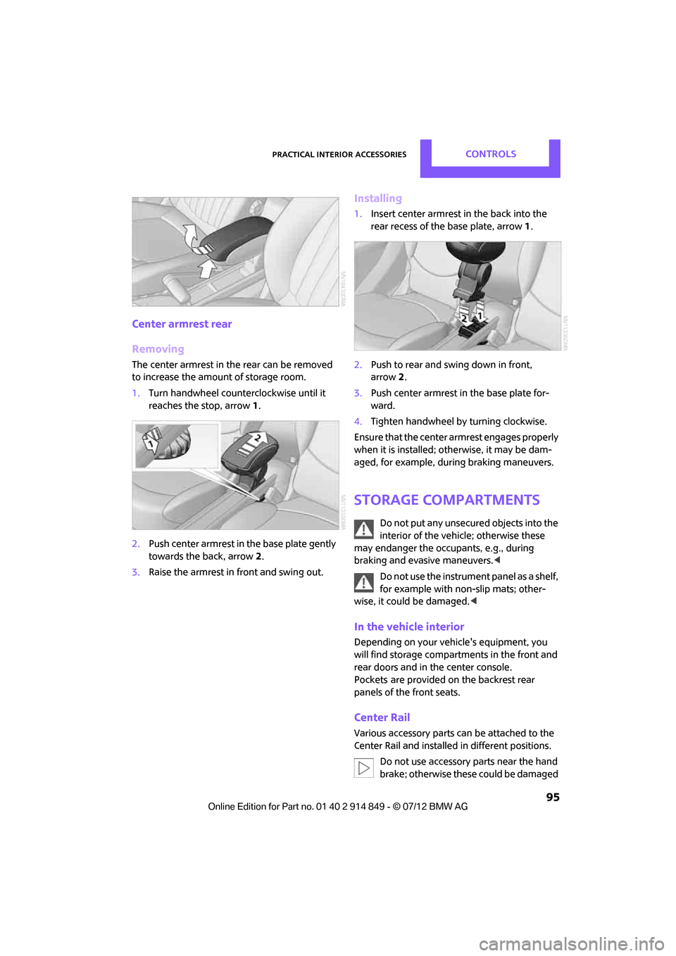
Center armrest rear
Removing
The center armrest in the rear can be removed
to increase the amo unt of storage room.
1. Turn handwheel counterclockwise until it
reaches the stop, arrow 1.
2. Push center armrest in the base plate gently
towards the back, arrow 2.
3. Raise the armrest in front and swing out.
Installing
1.Insert center armrest in the back into the
rear recess of the base plate, arrow 1.
2. Push to rear and sw ing down in front,
arrow 2.
3. Push center armrest in the base plate for-
ward.
4. Tighten handwheel by turning clockwise.
Ensure that the center armrest engages properly
when it is installed; ot herwise, it may be dam-
aged, for example, during braking maneuvers.
Storage compartments
Do not put any unsecured objects into the
interior of the vehicle; otherwise these
may endanger the occupants, e.g., during
braking and evasive maneuvers. <
Do not use the instrument panel as a shelf,
for example with non-slip mats; other-
wise, it could be damaged. <
In the vehicle interior
Depending on your vehicle's equipment, you
will find storage compartments in the front and
rear doors and in the center console.
Pockets
are provided on the backrest rear
panels of the front seats.
Center Rail
Various accessory parts ca n be attached to the
Center Rail and installed in different positions.
Do not use accessory parts near the hand
brake; otherwise these could be damaged
Online Edition for Part no. 01 40 2 914 849 - \251 07/12 BMW AG
Page 97 of 259

CONTROLSPractical interior accessories
96
when the hand brake lever is operated.
In addition, do not position accessory parts
directly behind the center armrest on the rail;
otherwise they could be damaged upon open-
ing the center armrest.<
Smartphone holder
The upper part of the smartphone holder can be
rotated by 360°.
When installing in the front of the rail, ensure
that there is sufficient space, e.g., away from the
seat; otherwise, damage may be caused when
rotating.
1.Pull the lever 1 up to unlock the mounts.
2. First install the smartphone on the Center
Rail with the mounts 2.
3. To secure, push lever 1 down. Ensure that
the lever can lock it properly.
When connecting a smartphone to the USB
audio interface, see page 150, guide the con-
nection cable under the smartphone holder.
Base plate
On the base plate, vari ous accessories can be
attached, such as cup holders, holders for sun-
glasses and cell phone holders.
Inserting base plate
The lever 3 can be locked in three positions.
0 Locking
1 Sliding along the rail
2 Inserting base plate
For inserting, move the lever into position 2.
Sliding and locking
1. Push lever 3 into position 1.
2. Slide the base plate.
3. Push the lever 3 down, into position 0, and
lock the base plate in place.
Lock the base plate in place before
driving; otherwise, injuries may result in
the event of an accident. <
Example: cupholder
Put cupholder in the back between the rear
seats and push in.
Installing cupholder
1.Lock base plate in place if necessary, refer to
Sliding and locking.
2. Pull the lever 6 up to unlock the mounts.
Online Edition for Part no. 01 40 2 914 849 - \251 07/12 BMW AG