ESP MINI Countryman 2014 Owner's Manual
[x] Cancel search | Manufacturer: MINI, Model Year: 2014, Model line: Countryman, Model: MINI Countryman 2014Pages: 218, PDF Size: 5.45 MB
Page 8 of 218
your skin by washing thoroughly with soap and
water.
Service and warranty
We recommend that you read this publication
thoroughly. Your vehicle is covered by the fol‐
lowing warranties:▷New Vehicle Limited Warranty.▷Rust Perforation Limited Warranty.▷Federal Emissions System Defect Warranty.▷Federal Emissions Performance Warranty.▷California Emission Control System Limited
Warranty.
Detailed information about these warranties is
listed in the Service and Warranty Information
Booklet for US models or in the Warranty and
Service Guide Booklet for Canadian models.
Your vehicle has been specifically adapted and
designed to meet the particular operating con‐
ditions and homologation requirements in your
country and continental region in order to de‐
liver the full driving pleasure while the vehicle is
operated under those conditions. If you wish to
operate your vehicle in another country or re‐
gion, you may be required to adapt your vehi‐
cle to meet different prevailing operating con‐
ditions and homologation requirements. You
should also be aware of any applicable war‐
ranty limitations or exclusions for such country
or region. In such case, please contact Cus‐
tomer Relations for further information.
Maintenance
Maintain the vehicle regularly to sustain the
road safety, operational reliability and the New
Vehicle Limited Warranty.
Specifications for required maintenance meas‐
ures:
▷MINI Maintenance system▷Service and Warranty Information Booklet
for US models▷Warranty and Service Guide Booklet for
Canadian modelsIf the vehicle is not maintained according to
these specifications, this could result in serious
damage to the vehicle. Such damage is not
covered by the MINI New Vehicle Limited War‐
ranty.
Data memory
Numerous electronic components in your vehi‐
cle contain data memories that store technical
information on the vehicle condition, events and faults, either temporarily or permanently.This technical information generally documents
the state of a component, a module, a system
or the environment.▷Operating conditions of system compo‐
nents, such as filling levels.▷Status messages from the vehicle and its in‐
dividual components, such as wheel rpm/
speed, motion delay, transverse accelera‐
tion.▷Malfunctions and defects in important sys‐
tem components, such as lights and brakes.▷Vehicle responses to special driving situa‐
tions, such as airbag deployment, use of
the stability control systems.▷Ambient conditions, such as the tempera‐
ture.
These data are of a technical nature only and
are used to detect and eliminate faults and to
optimize vehicle functions. Travel profiles of
routes driven with the vehicle cannot be cre‐
ated from these data. If services are used, for
instance in the event of repairs, service proc‐
esses, warranty cases, quality assurance, etc.,
this technical information can be read out from
the event and fault data memories by service
personnel, including the manufacturer, using
special diagnosis tools. This service personnel
can provide you with more information if
needed. After troubleshooting, the information
in the fault memory is cleared or overwritten
continuously.
Seite 8Notes8
Online Edition for Part no. 01 40 2 911 521 - VI/13
Page 17 of 218
Indicator/warning lamps
The concept
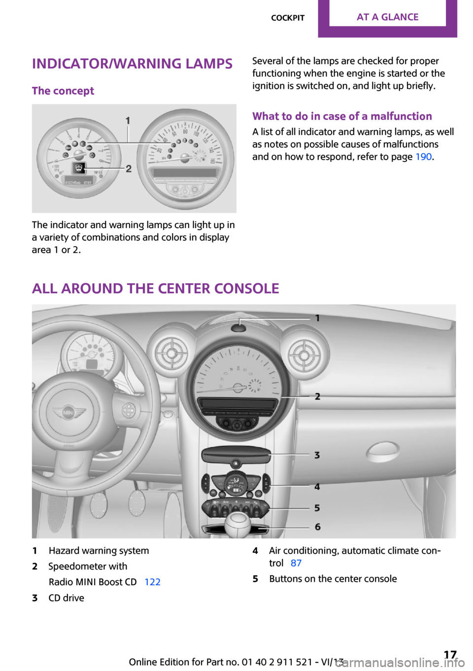
The indicator and warning lamps can light up in
a variety of combinations and colors in display
area 1 or 2.
Several of the lamps are checked for proper
functioning when the engine is started or the
ignition is switched on, and light up briefly.
What to do in case of a malfunction
A list of all indicator and warning lamps, as well
as notes on possible causes of malfunctions
and on how to respond, refer to page 190.
All around the center console
1Hazard warning system2Speedometer with
Radio MINI Boost CD 1223CD drive4Air conditioning, automatic climate con‐
trol 875Buttons on the center consoleSeite 17CockpitAt a glance17
Online Edition for Part no. 01 40 2 911 521 - VI/13
Page 23 of 218
stored with it are called up and imple‐
mented.▷Your personal settings will be recognized
and called up again even if the vehicle has
been used in the meantime by someone
else with another remote control.▷The individual settings are stored for no
more than three remote controls.
Personal Profile settings
The following functions and settings can be
stored in a profile.
More information on the settings can be found
under:
▷Response of the central locking system
when the car is being unlocked, refer to
page 24.▷Automatic locking of the vehicle, refer to
page 28.▷Triple turn signal activation, refer to
page 52.▷Settings for the displays in the speedometer
and tachometer:▷12h/24h clock format, refer to
page 62.▷Date format, refer to page 62.▷Units of measure for fuel consumption,
distance covered/remaining distances,
and temperature, refer to page 62.▷Light settings:▷Headlamp courtesy delay feature, refer
to page 69.▷Daytime running lights, refer to
page 68.▷Automatic climate control, refer to
page 89: AUTO program, activating/deac‐
tivating the cooling function, setting the
temperature, air volume, and air distribu‐
tion.▷Entertainment:▷Last entertainment source.▷Radio MINI Boost CD:
Tone settings, refer to page 124.
Volume, refer to page 124.
Central locking system
The concept
The central locking system becomes active
when the driver's door is closed.
The system simultaneously engages and re‐
leases the locks on the following:
▷Doors.▷Tailgate.▷Fuel filler flap.
Operating from the outside
▷Via the remote control.▷Via the door lock.▷In cars with Comfort Access, via the door
handles on the driver's and front passenger
sides.
The following takes place simultaneously when
locking/unlocking the vehicle via the remote
control:
▷Depending on the vehicle equipment, the
anti-theft protection is switched on and off
as well. The anti-theft protection makes it
impossible to unlock the doors using the
lock buttons or door handles.▷The welcome lamps, interior lamps, and
ambient lighting are switched on and off.▷The alarm system is armed or disarmed, re‐
fer to page 32.
Operating from the inside
Via the switch/button for the central locking
system, refer to page 27.
In an accident of the necessary severity, the
central locking system unlocks automatically.
Seite 23Opening and closingControls23
Online Edition for Part no. 01 40 2 911 521 - VI/13
Page 30 of 218
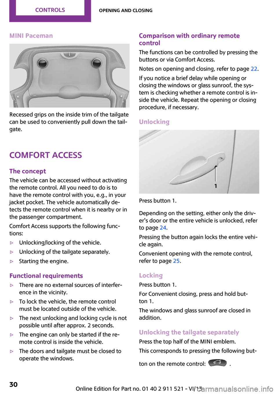
MINI Paceman
Recessed grips on the inside trim of the tailgate
can be used to conveniently pull down the tail‐
gate.
Comfort Access The concept
The vehicle can be accessed without activating
the remote control. All you need to do is to
have the remote control with you, e.g., in your
jacket pocket. The vehicle automatically de‐
tects the remote control when it is nearby or in
the passenger compartment.
Comfort Access supports the following func‐
tions:
▷Unlocking/locking of the vehicle.▷Unlocking of the tailgate separately.▷Starting the engine.
Functional requirements
▷There are no external sources of interfer‐
ence in the vicinity.▷To lock the vehicle, the remote control
must be located outside of the vehicle.▷The next unlocking and locking cycle is not
possible until after approx. 2 seconds.▷The engine can only be started if the re‐
mote control is inside the vehicle.▷The doors and tailgate must be closed to
operate the windows.Comparison with ordinary remote
control
The functions can be controlled by pressing the
buttons or via Comfort Access.
Notes on opening and closing, refer to page 22.
If you notice a brief delay while opening or
closing the windows or glass sunroof, the sys‐
tem is checking whether a remote control is in‐
side the vehicle. Repeat the opening or closing
procedure, if necessary.
Unlocking
Press button 1.
Depending on the setting, either only the driv‐
er's door or the entire vehicle is unlocked, refer
to page 24.
Pressing the button again locks the entire vehi‐
cle again.
Convenient opening with the remote control,
refer to page 25.
Locking
Press button 1.
For Convenient closing, press and hold but‐
ton 1.
The windows and glass sunroof are closed in addition.
Unlocking the tailgate separately
Press the top half of the MINI emblem.
This corresponds to pressing the following but‐
ton on the remote control:
.
Seite 30ControlsOpening and closing30
Online Edition for Part no. 01 40 2 911 521 - VI/13
Page 32 of 218
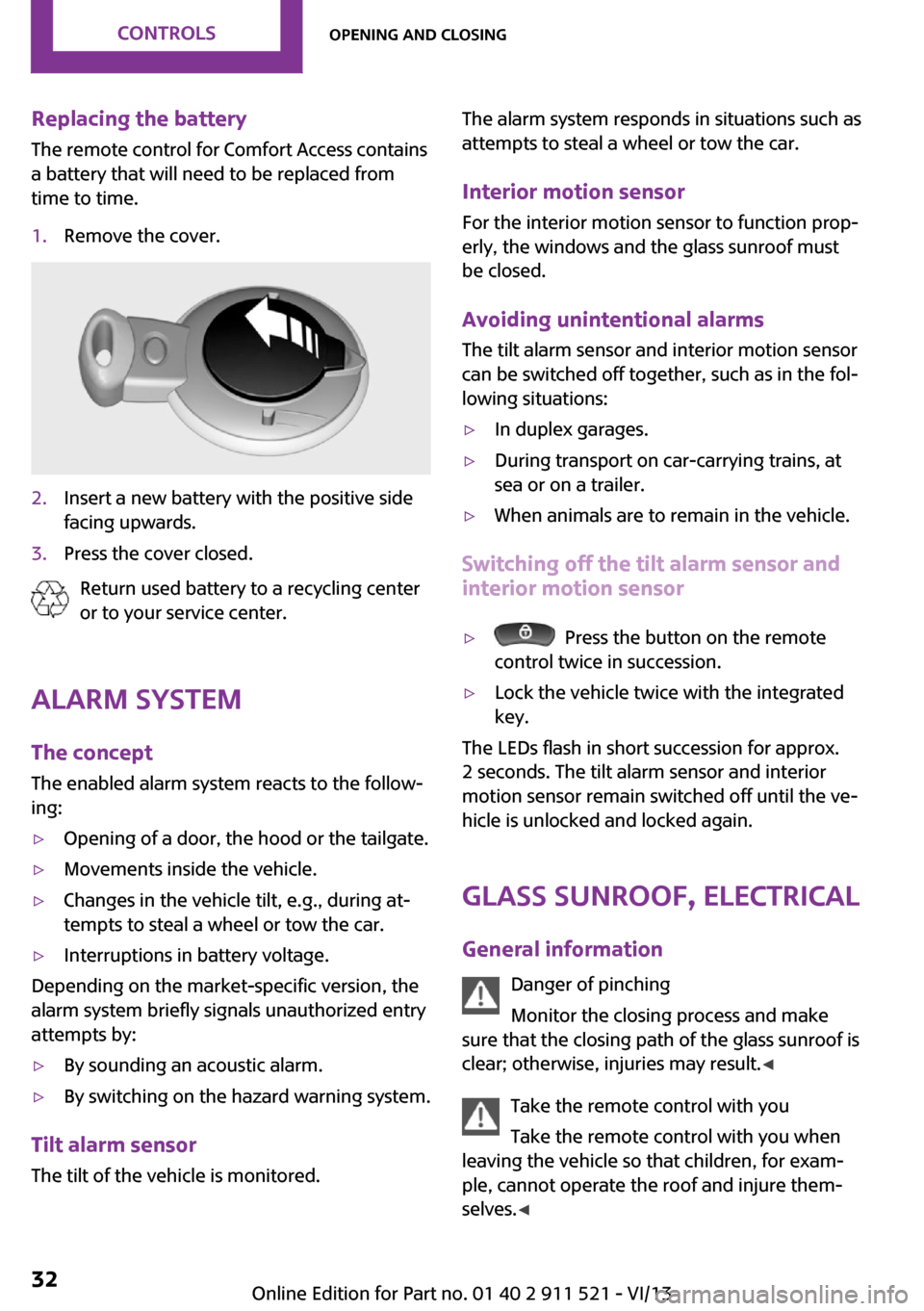
Replacing the battery
The remote control for Comfort Access contains
a battery that will need to be replaced from
time to time.1.Remove the cover.2.Insert a new battery with the positive side
facing upwards.3.Press the cover closed.
Return used battery to a recycling center
or to your service center.
Alarm system
The concept
The enabled alarm system reacts to the follow‐
ing:
▷Opening of a door, the hood or the tailgate.▷Movements inside the vehicle.▷Changes in the vehicle tilt, e.g., during at‐
tempts to steal a wheel or tow the car.▷Interruptions in battery voltage.
Depending on the market-specific version, the
alarm system briefly signals unauthorized entry
attempts by:
▷By sounding an acoustic alarm.▷By switching on the hazard warning system.
Tilt alarm sensor
The tilt of the vehicle is monitored.
The alarm system responds in situations such as
attempts to steal a wheel or tow the car.
Interior motion sensor For the interior motion sensor to function prop‐
erly, the windows and the glass sunroof must
be closed.
Avoiding unintentional alarms
The tilt alarm sensor and interior motion sensor
can be switched off together, such as in the fol‐
lowing situations:▷In duplex garages.▷During transport on car-carrying trains, at
sea or on a trailer.▷When animals are to remain in the vehicle.
Switching off the tilt alarm sensor and
interior motion sensor
▷ Press the button on the remote
control twice in succession.▷Lock the vehicle twice with the integrated
key.
The LEDs flash in short succession for approx.
2 seconds. The tilt alarm sensor and interior
motion sensor remain switched off until the ve‐
hicle is unlocked and locked again.
Glass sunroof, electrical
General information Danger of pinching
Monitor the closing process and make
sure that the closing path of the glass sunroof is
clear; otherwise, injuries may result. ◀
Take the remote control with you
Take the remote control with you when
leaving the vehicle so that children, for exam‐
ple, cannot operate the roof and injure them‐
selves. ◀
Seite 32ControlsOpening and closing32
Online Edition for Part no. 01 40 2 911 521 - VI/13
Page 36 of 218
AdjustingVehicle equipment
This chapter describes all series equipment as
well as country-specific and special equipment
offered for this model series.Therefore, it also
describes equipment that may not be found in
your vehicle, for instance due to the selected
special equipment or the country version. This
also applies to safety-related functions and sys‐
tems.
Sitting safely The ideal seating position can make a vital con‐
tribution to relaxed, fatigue-free driving.
The seating position plays an important role in
an accident in combination with:▷Safety belts, refer to page 38▷Head restraints, refer to page 41.▷Airbags, refer to page 72.
Seats
Note before adjusting Do not adjust the seat while driving
Never attempt to adjust the driver's seat
while driving. The seat could respond with un‐
expected movement and the ensuing loss of
vehicle control could lead to an accident. ◀
Do not incline the backrest too far to the
rear
Do not incline the backrest on the front passen‐
ger side too far to the rear during driving. Oth‐
erwise, there is the danger of sliding under the
safety belt in an accident. This would eliminate
the protection normally provided by the belt. ◀
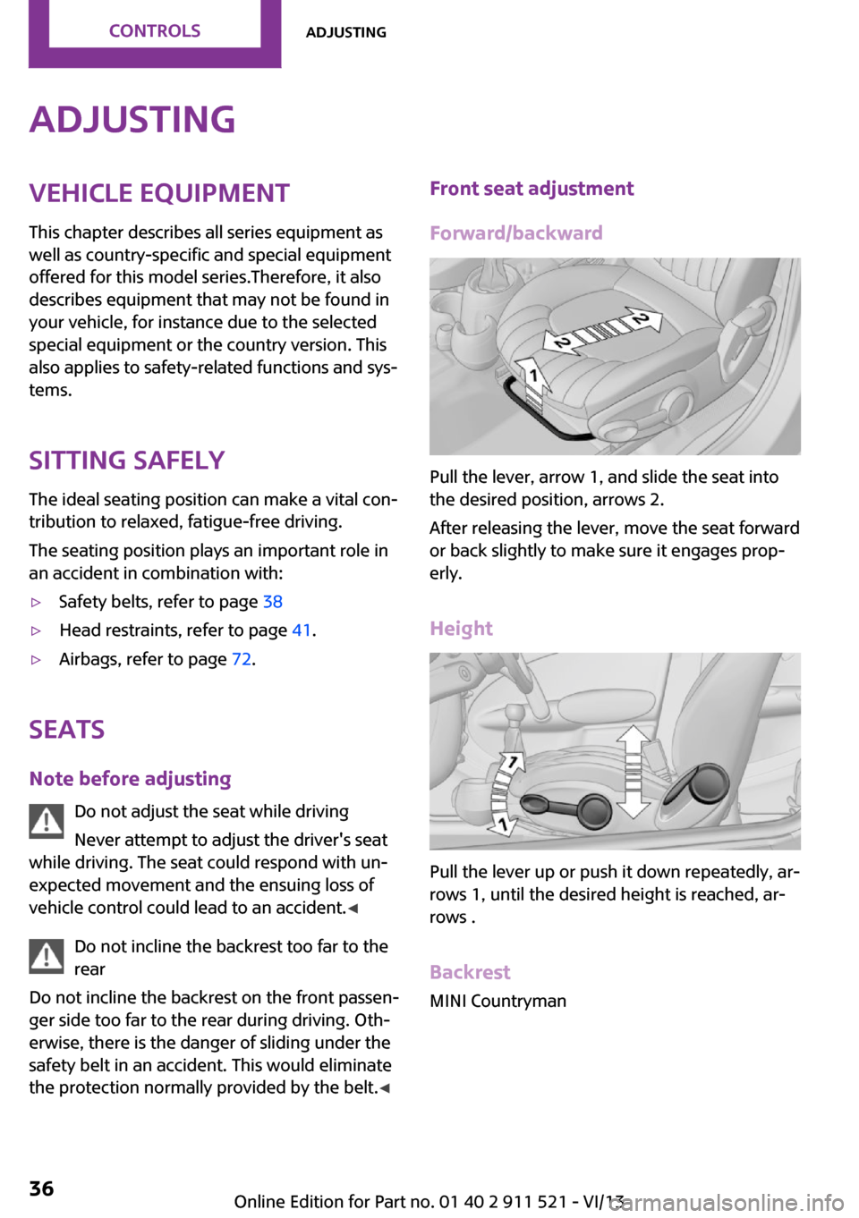
Front seat adjustment
Forward/backward
Pull the lever, arrow 1, and slide the seat into
the desired position, arrows 2.
After releasing the lever, move the seat forward
or back slightly to make sure it engages prop‐
erly.
Height
Pull the lever up or push it down repeatedly, ar‐
rows 1, until the desired height is reached, ar‐
rows .
Backrest MINI Countryman
Seite 36ControlsAdjusting36
Online Edition for Part no. 01 40 2 911 521 - VI/13
Page 40 of 218

1Opening for the safety belt2Holder for the small buckle tongue
Take the small buckle tongue out of the holder.
Move both buckle tongues downward.
Closing
Insert the small buckle tongue 2 of the safety
belt into the small belt buckle 3.
Opening Press the red button on the small belt buckle 3
with buckle tongue 1.
When the center safety belt is locked:
Press the red button 3 with the buckle tongue
of the outer left safety belt.
Putting on the belt1Large buckle tongue2Small buckle tongue3Small belt buckle4Large belt buckle
Buckle tongue 1 must be inserted in belt
buckle 4. Make sure you hear the buckle
tongue engage in the belt buckle.
Insert the buckle tongue into the belt buckle in
such a way that the belt lies smoothly against
the body of the buckled person and is not
twisted.
Stowing the center safety belt
If the center seat is not occupied, insert the belt
buckles 3 and 4 into the respective holders, ar‐
rows.
Move the buckle tongues to the belt holder on
the headliner, refer to page 39, and insert them
into the provided holders.
Seite 40ControlsAdjusting40
Online Edition for Part no. 01 40 2 911 521 - VI/13
Page 42 of 218
Rear1.Pull upward as far as possible.2.Fold the backrest forward slightly.3.Press button 1 and pull out the head re‐
straint all the way to the stop.4.Press the additional button 2 using a suita‐
ble tool.5.Pull out the head restraint completely.6.Fold back the rear seat backrest.
Mirrors
Exterior mirrors
General information
The mirror on the passenger side is more
curved than the driver's mirror.
Estimating distances correctly
Objects reflected in the mirror are closer
than they appear. Do not estimate the distance to the traffic behind you based on what you see
in the mirror, as this will increase your risk of an
accident. ◀
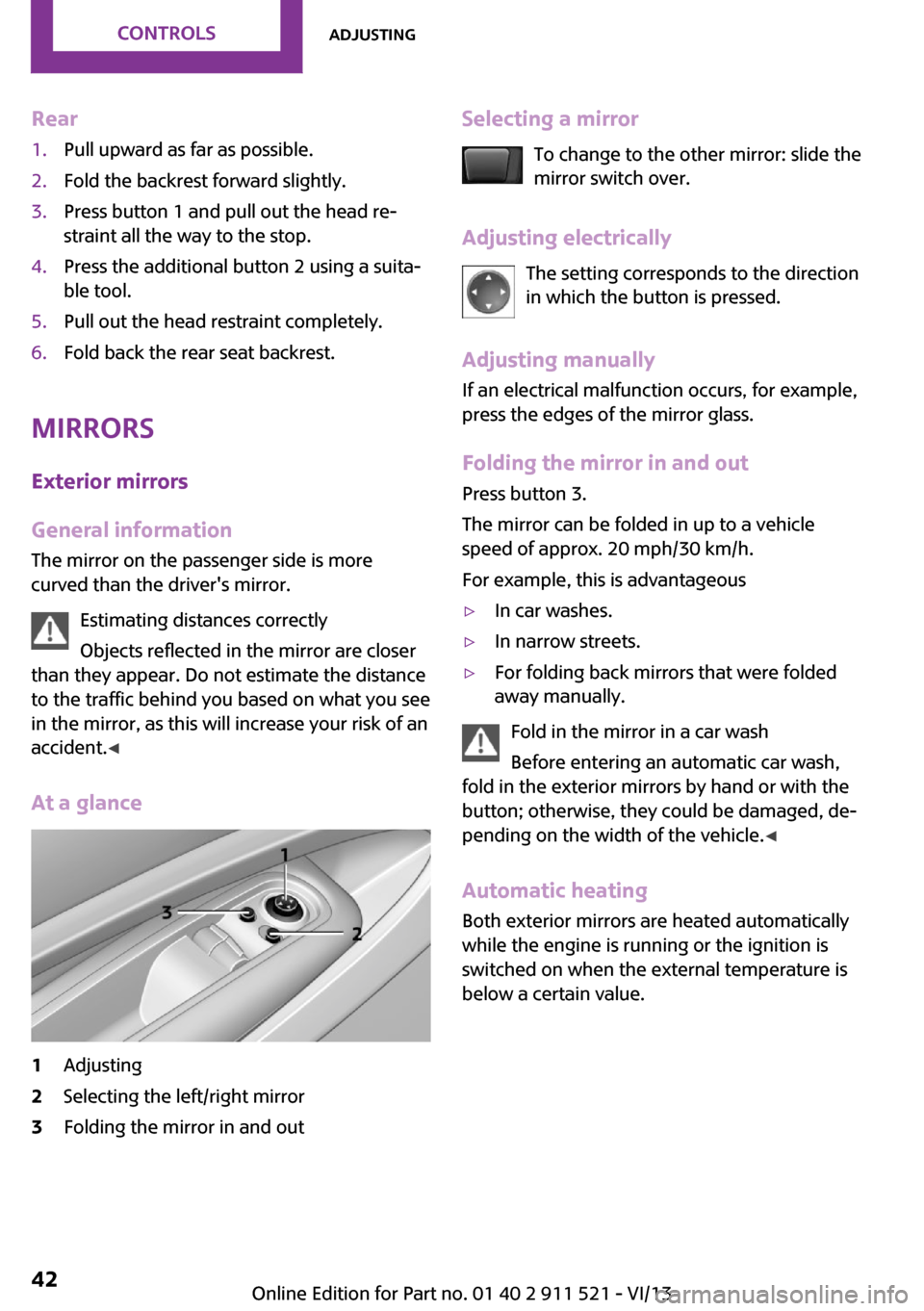
At a glance
1Adjusting2Selecting the left/right mirror3Folding the mirror in and outSelecting a mirror To change to the other mirror: slide the
mirror switch over.
Adjusting electrically The setting corresponds to the direction
in which the button is pressed.
Adjusting manually If an electrical malfunction occurs, for example,
press the edges of the mirror glass.
Folding the mirror in and out
Press button 3.
The mirror can be folded in up to a vehicle
speed of approx. 20 mph/30 km/h.
For example, this is advantageous▷In car washes.▷In narrow streets.▷For folding back mirrors that were folded
away manually.
Fold in the mirror in a car wash
Before entering an automatic car wash,
fold in the exterior mirrors by hand or with the
button; otherwise, they could be damaged, de‐
pending on the width of the vehicle. ◀
Automatic heating Both exterior mirrors are heated automatically
while the engine is running or the ignition is
switched on when the external temperature is
below a certain value.
Seite 42ControlsAdjusting42
Online Edition for Part no. 01 40 2 911 521 - VI/13
Page 44 of 218
Transporting children safelyVehicle equipment
This chapter describes all series equipment as
well as country-specific and special equipment
offered for this model series.Therefore, it also
describes equipment that may not be found in
your vehicle, for instance due to the selected
special equipment or the country version. This
also applies to safety-related functions and sys‐
tems.
The right place for chil‐
dren
Notes Children in the vehicle
Do not leave children unattended in the
vehicle; otherwise, they could endanger them‐
selves and other persons, e.g., by opening the
doors. ◀
Children should always be in the rear Accident research shows that the safest place
for children is on the rear seat.
Transporting children in the rear
Transport children younger than 13 years
of age or shorter than 5 ft/150 cm in the rear
only, using child restraint fixing systems suita‐
ble for the age, weight, and height of the child; otherwise, there is an increased risk of injury in
an accident.
Children 13 years of age or older must wear a
safety belt as soon as a suitable child restraint fixing system can no longer be used, due to
their age, weight and size. ◀Installing child seats
Only install child seats in the rear when
the rear seat backrest is folded all the way back
and engaged; otherwise, there is an increased
risk of injury in an accident. ◀
Children on the front passenger seat
Front passenger airbags Should it be necessary to use a child restraint
fixing system on the front passenger seat,
make sure that the front and side airbags on
the front passenger side are deactivated, refer
to page 73.
Deactivating the front passenger airbags
If a child restraint fixing system is used in
the front passenger seat, the front passenger
airbags must be deactivated; otherwise, there
is an increased risk of injury to the child when
the airbags are triggered, even with a child re‐
straint fixing system. ◀
Installing child re‐
straint fixing systems
Before mounting MINI Countryman: before mounting a child re‐
straint fixing system on the rear seats, move
the seats into the rearmost positions.
Adjust the inclination of the center backrest to
that of the respective outer backrest.
After mounting the child restraint fixing system
on the respective outer rear seat, adjust the
backrest forward, if necessary, to ensure that
the backrest is in contact with the child re‐
straint fixing system. Rear seat backrests, refer
to page 98.Seite 44ControlsTransporting children safely44
Online Edition for Part no. 01 40 2 911 521 - VI/13
Page 59 of 218
DisplaysVehicle equipment
This chapter describes all series equipment as
well as country-specific and special equipment
offered for this model series.Therefore, it also
describes equipment that may not be found in
your vehicle, for instance due to the selected
special equipment or the country version. This
also applies to safety-related functions and sys‐
tems.
Odometer, external tem‐
perature display, clock
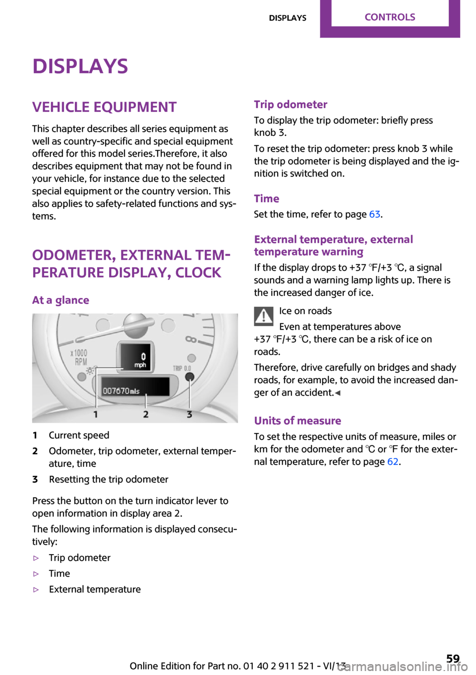
At a glance1Current speed2Odometer, trip odometer, external temper‐
ature, time3Resetting the trip odometer
Press the button on the turn indicator lever to
open information in display area 2.
The following information is displayed consecu‐
tively:
▷Trip odometer▷Time▷External temperatureTrip odometer
To display the trip odometer: briefly press
knob 3.
To reset the trip odometer: press knob 3 while
the trip odometer is being displayed and the ig‐
nition is switched on.
Time Set the time, refer to page 63.
External temperature, external temperature warning
If the display drops to +37 ℉/+3 ℃, a signal
sounds and a warning lamp lights up. There is
the increased danger of ice.
Ice on roads
Even at temperatures above
+37 ℉/+3 ℃, there can be a risk of ice on
roads.
Therefore, drive carefully on bridges and shady
roads, for example, to avoid the increased dan‐
ger of an accident. ◀
Units of measure
To set the respective units of measure, miles or
km for the odometer and ℃ or ℉ for the exter‐
nal temperature, refer to page 62.Seite 59DisplaysControls59
Online Edition for Part no. 01 40 2 911 521 - VI/13