Temperature MINI Countryman 2014 Owner's Manual
[x] Cancel search | Manufacturer: MINI, Model Year: 2014, Model line: Countryman, Model: MINI Countryman 2014Pages: 218, PDF Size: 5.45 MB
Page 23 of 218
stored with it are called up and imple‐
mented.▷Your personal settings will be recognized
and called up again even if the vehicle has
been used in the meantime by someone
else with another remote control.▷The individual settings are stored for no
more than three remote controls.
Personal Profile settings
The following functions and settings can be
stored in a profile.
More information on the settings can be found
under:
▷Response of the central locking system
when the car is being unlocked, refer to
page 24.▷Automatic locking of the vehicle, refer to
page 28.▷Triple turn signal activation, refer to
page 52.▷Settings for the displays in the speedometer
and tachometer:▷12h/24h clock format, refer to
page 62.▷Date format, refer to page 62.▷Units of measure for fuel consumption,
distance covered/remaining distances,
and temperature, refer to page 62.▷Light settings:▷Headlamp courtesy delay feature, refer
to page 69.▷Daytime running lights, refer to
page 68.▷Automatic climate control, refer to
page 89: AUTO program, activating/deac‐
tivating the cooling function, setting the
temperature, air volume, and air distribu‐
tion.▷Entertainment:▷Last entertainment source.▷Radio MINI Boost CD:
Tone settings, refer to page 124.
Volume, refer to page 124.
Central locking system
The concept
The central locking system becomes active
when the driver's door is closed.
The system simultaneously engages and re‐
leases the locks on the following:
▷Doors.▷Tailgate.▷Fuel filler flap.
Operating from the outside
▷Via the remote control.▷Via the door lock.▷In cars with Comfort Access, via the door
handles on the driver's and front passenger
sides.
The following takes place simultaneously when
locking/unlocking the vehicle via the remote
control:
▷Depending on the vehicle equipment, the
anti-theft protection is switched on and off
as well. The anti-theft protection makes it
impossible to unlock the doors using the
lock buttons or door handles.▷The welcome lamps, interior lamps, and
ambient lighting are switched on and off.▷The alarm system is armed or disarmed, re‐
fer to page 32.
Operating from the inside
Via the switch/button for the central locking
system, refer to page 27.
In an accident of the necessary severity, the
central locking system unlocks automatically.
Seite 23Opening and closingControls23
Online Edition for Part no. 01 40 2 911 521 - VI/13
Page 38 of 218
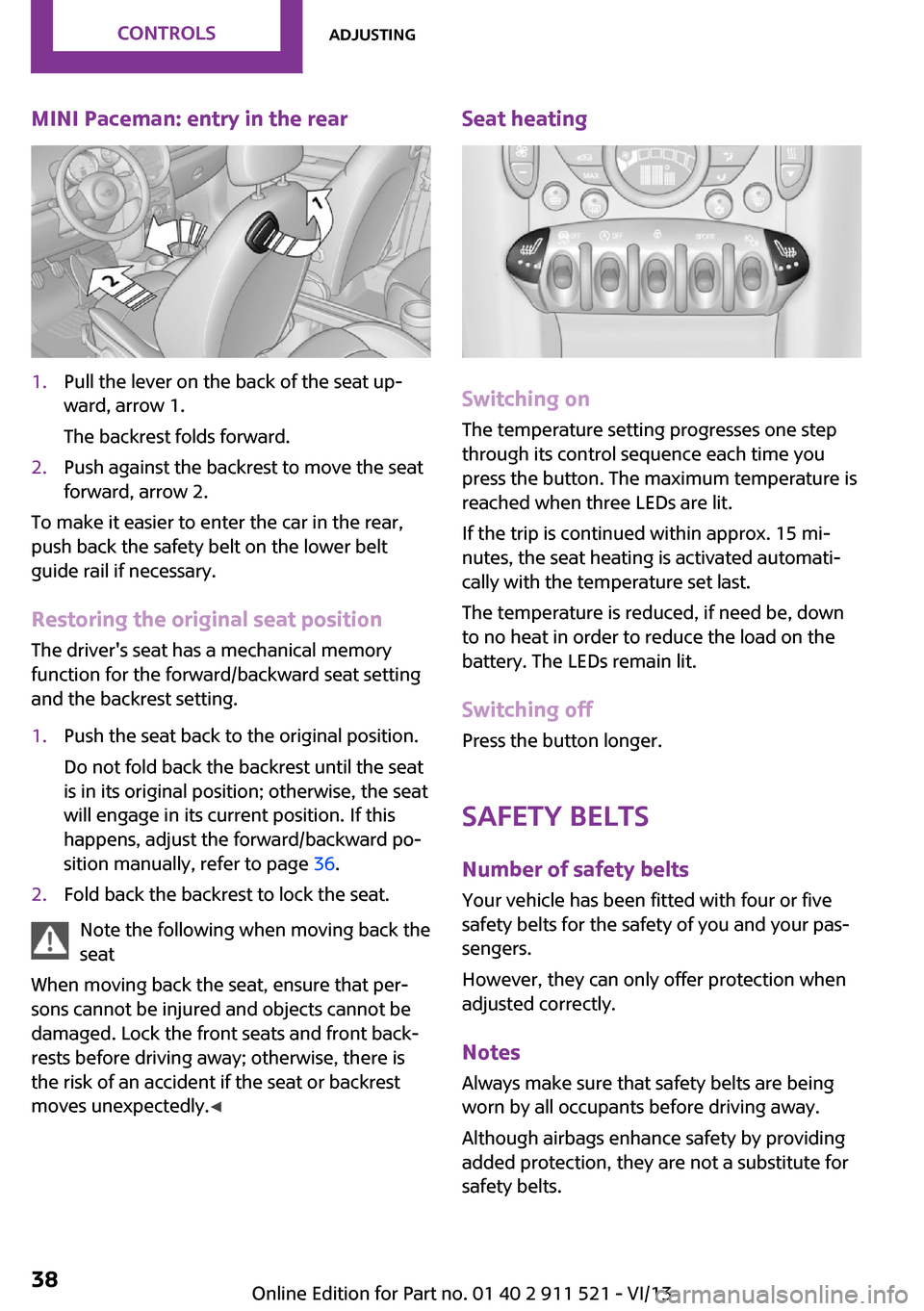
MINI Paceman: entry in the rear1.Pull the lever on the back of the seat up‐
ward, arrow 1.
The backrest folds forward.2.Push against the backrest to move the seat
forward, arrow 2.
To make it easier to enter the car in the rear,
push back the safety belt on the lower belt
guide rail if necessary.
Restoring the original seat position The driver's seat has a mechanical memory
function for the forward/backward seat setting
and the backrest setting.
1.Push the seat back to the original position.
Do not fold back the backrest until the seat
is in its original position; otherwise, the seat
will engage in its current position. If this
happens, adjust the forward/backward po‐
sition manually, refer to page 36.2.Fold back the backrest to lock the seat.
Note the following when moving back the
seat
When moving back the seat, ensure that per‐
sons cannot be injured and objects cannot be
damaged. Lock the front seats and front back‐
rests before driving away; otherwise, there is
the risk of an accident if the seat or backrest
moves unexpectedly. ◀
Seat heating
Switching on
The temperature setting progresses one step
through its control sequence each time you
press the button. The maximum temperature is
reached when three LEDs are lit.
If the trip is continued within approx. 15 mi‐
nutes, the seat heating is activated automati‐
cally with the temperature set last.
The temperature is reduced, if need be, down
to no heat in order to reduce the load on the
battery. The LEDs remain lit.
Switching off
Press the button longer.
Safety beltsNumber of safety belts
Your vehicle has been fitted with four or five
safety belts for the safety of you and your pas‐
sengers.
However, they can only offer protection when
adjusted correctly.
NotesAlways make sure that safety belts are beingworn by all occupants before driving away.
Although airbags enhance safety by providing
added protection, they are not a substitute for
safety belts.
Seite 38ControlsAdjusting38
Online Edition for Part no. 01 40 2 911 521 - VI/13
Page 42 of 218
Rear1.Pull upward as far as possible.2.Fold the backrest forward slightly.3.Press button 1 and pull out the head re‐
straint all the way to the stop.4.Press the additional button 2 using a suita‐
ble tool.5.Pull out the head restraint completely.6.Fold back the rear seat backrest.
Mirrors
Exterior mirrors
General information
The mirror on the passenger side is more
curved than the driver's mirror.
Estimating distances correctly
Objects reflected in the mirror are closer
than they appear. Do not estimate the distance to the traffic behind you based on what you see
in the mirror, as this will increase your risk of an
accident. ◀
At a glance
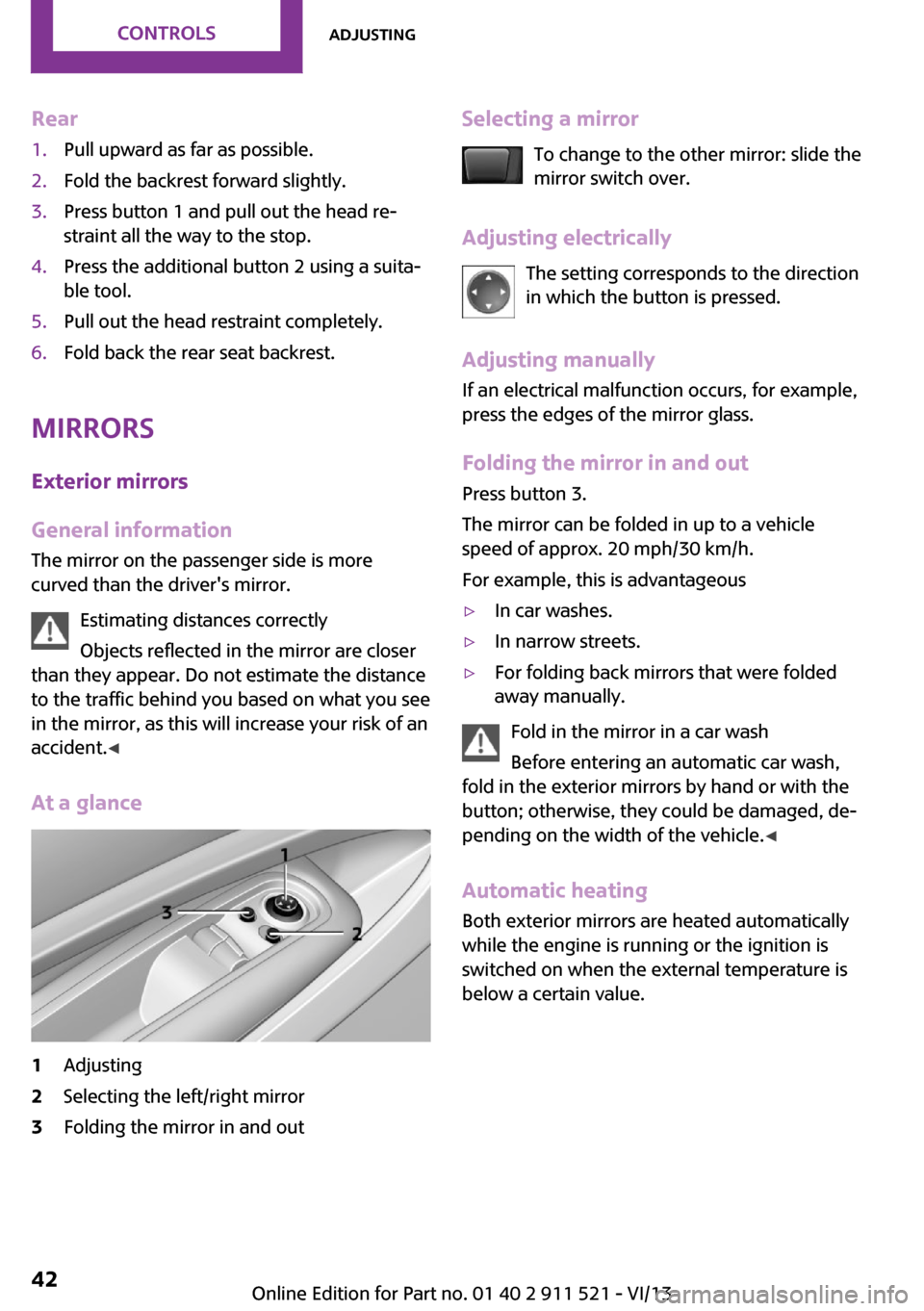
1Adjusting2Selecting the left/right mirror3Folding the mirror in and outSelecting a mirror To change to the other mirror: slide the
mirror switch over.
Adjusting electrically The setting corresponds to the direction
in which the button is pressed.
Adjusting manually If an electrical malfunction occurs, for example,
press the edges of the mirror glass.
Folding the mirror in and out
Press button 3.
The mirror can be folded in up to a vehicle
speed of approx. 20 mph/30 km/h.
For example, this is advantageous▷In car washes.▷In narrow streets.▷For folding back mirrors that were folded
away manually.
Fold in the mirror in a car wash
Before entering an automatic car wash,
fold in the exterior mirrors by hand or with the
button; otherwise, they could be damaged, de‐
pending on the width of the vehicle. ◀
Automatic heating Both exterior mirrors are heated automatically
while the engine is running or the ignition is
switched on when the external temperature is
below a certain value.
Seite 42ControlsAdjusting42
Online Edition for Part no. 01 40 2 911 521 - VI/13
Page 54 of 218

Activating intermittent wipe or rain
sensor
Press the button, arrow 3.
The symbol is shown in the tachometer.
Setting the sensitivity of the rain sensor1.Switch on the ignition, refer to page 49.2.Press the button on the turn indicator lever
repeatedly until "SET/INFO" is displayed.3.Press and hold the button until the display
changes.4.Press the button repeatedly until the sym‐
bol and "SET" are displayed.5.Press and hold the button until the display
changes.6.Press the button to select the desired sensi‐
tivity.7.Wait or hold the button until the display
changes.
The settings were stored.
Deactivating intermittent wipe or rain
sensor
Press the button again, arrow 3.
Cleaning the windshield and headlamps
Pull the lever, arrow 4.
The system sprays washer fluid on the wind‐
shield and activates the wipers briefly.
When the vehicle lighting system is switched
on, the headlamps are cleaned at regular and
appropriate intervals.
Do not use the washer system at freezing
temperatures
Do not use the washers if there is any danger
that the fluid will freeze on the windshield; oth‐
erwise, your vision could be obscured. For this
reason, use antifreeze.
Avoid using the washer when the reservoir is
empty; otherwise, you could damage the
pump. ◀
Seite 54ControlsDriving54
Online Edition for Part no. 01 40 2 911 521 - VI/13
Page 59 of 218
DisplaysVehicle equipment
This chapter describes all series equipment as
well as country-specific and special equipment
offered for this model series.Therefore, it also
describes equipment that may not be found in
your vehicle, for instance due to the selected
special equipment or the country version. This
also applies to safety-related functions and sys‐
tems.
Odometer, external tem‐
perature display, clock
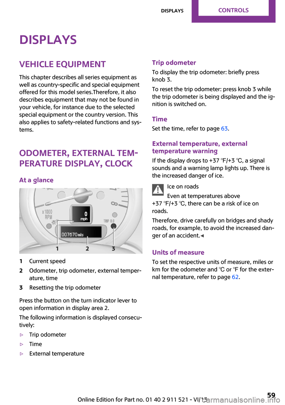
At a glance1Current speed2Odometer, trip odometer, external temper‐
ature, time3Resetting the trip odometer
Press the button on the turn indicator lever to
open information in display area 2.
The following information is displayed consecu‐
tively:
▷Trip odometer▷Time▷External temperatureTrip odometer
To display the trip odometer: briefly press
knob 3.
To reset the trip odometer: press knob 3 while
the trip odometer is being displayed and the ig‐
nition is switched on.
Time Set the time, refer to page 63.
External temperature, external temperature warning
If the display drops to +37 ℉/+3 ℃, a signal
sounds and a warning lamp lights up. There is
the increased danger of ice.
Ice on roads
Even at temperatures above
+37 ℉/+3 ℃, there can be a risk of ice on
roads.
Therefore, drive carefully on bridges and shady
roads, for example, to avoid the increased dan‐
ger of an accident. ◀
Units of measure
To set the respective units of measure, miles or
km for the odometer and ℃ or ℉ for the exter‐
nal temperature, refer to page 62.Seite 59DisplaysControls59
Online Edition for Part no. 01 40 2 911 521 - VI/13
Page 60 of 218
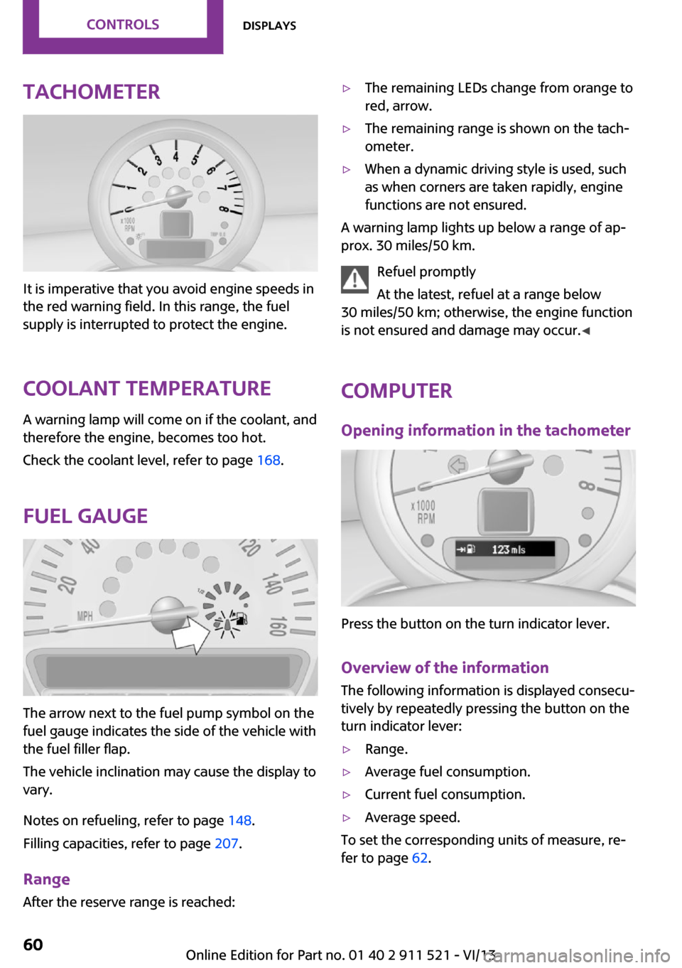
Tachometer
It is imperative that you avoid engine speeds in
the red warning field. In this range, the fuel
supply is interrupted to protect the engine.
Coolant temperature A warning lamp will come on if the coolant, and
therefore the engine, becomes too hot.
Check the coolant level, refer to page 168.
Fuel gauge
The arrow next to the fuel pump symbol on the
fuel gauge indicates the side of the vehicle with
the fuel filler flap.
The vehicle inclination may cause the display to
vary.
Notes on refueling, refer to page 148.
Filling capacities, refer to page 207.
Range After the reserve range is reached:
▷The remaining LEDs change from orange to
red, arrow.▷The remaining range is shown on the tach‐
ometer.▷When a dynamic driving style is used, such
as when corners are taken rapidly, engine
functions are not ensured.
A warning lamp lights up below a range of ap‐
prox. 30 miles/50 km.
Refuel promptly
At the latest, refuel at a range below
30 miles/50 km; otherwise, the engine function
is not ensured and damage may occur. ◀
Computer
Opening information in the tachometer
Press the button on the turn indicator lever.
Overview of the information
The following information is displayed consecu‐
tively by repeatedly pressing the button on the
turn indicator lever:
▷Range.▷Average fuel consumption.▷Current fuel consumption.▷Average speed.
To set the corresponding units of measure, re‐
fer to page 62.
Seite 60ControlsDisplays60
Online Edition for Part no. 01 40 2 911 521 - VI/13
Page 63 of 218

▷ Distance: km, mi.▷ Temperature: ℃, ℉7.Press and hold the button until the display
changes.8.Press the button to change the format or
the unit of measure.9.Press and hold the button until the display
changes.
The settings are stored.
Resetting to factory settings
The settings for formats and units of measure
can be reset to the factory settings. The settings
are stored for the remote control in use.
1.Press the button on the turn indicator lever
repeatedly until "SET/INFO" is displayed.2.Press and hold the button until the display
changes.3.Press the button repeatedly until the sym‐
bol and "SET" are displayed.4.Press and hold the button until the display
changes.5.Press the button repeatedly until "RESET"
appears on the display.6.Press and hold the button until the display
changes to the first setting option.
The settings are reset.
Clock
Setting the time Radio MINI Boost CD: setting the time, refer to
page 124.
Date
Setting the date
Radio MINI Boost CD: set the date, refer to
page 124.
Seite 63DisplaysControls63
Online Edition for Part no. 01 40 2 911 521 - VI/13
Page 77 of 218
Continued driving with a flat tire
If continuing to drive with a damaged tire:1.Avoid sudden braking and steering maneu‐
vers.2.Do not exceed a speed of 50 mph/80 km/h.3.At the next opportunity, check the inflation
pressure in all four tires.
If the tire inflation pressure in all four tires is
correct, the Flat Tire Monitor may not have
been initialized. In this case, initialize the
system.
Possible driving distance with complete loss of
tire inflation pressure:
The possible driving distance after a loss of tire
inflation pressure depends on the cargo load
and the driving style and conditions.
For a vehicle containing an average load, the
possible driving distance is ap‐
prox. 50 miles/80 km.
When the vehicle is driven with a damaged tire,
its handling characteristics change, e.g., re‐
duced lane stability during braking, a longer
braking distance, and altered self-steering
properties. Adjust your driving style accord‐
ingly. Avoid abrupt steering maneuvers or driv‐
ing over obstacles, e. g., curbs, potholes, etc.
Because the possible driving distance depends
on how the vehicle is used during the trip, the
actual distance may be smaller or greater de‐
pending on the driving speed, road conditions,
external temperature, cargo load, etc.
Continued driving with a flat tire
Drive moderately and do not exceed a
speed of 50 mph/80 km/h.
A loss of tire inflation pressure results in a
change in the handling characteristics, e.g., re‐
duced lane stability during braking, a longer
braking distance and altered self-steering prop‐
erties. ◀
Final tire failure
Vibrations or loud noises while driving
can indicate the final failure of the tire. Reduce
speed and stop; otherwise, pieces of the tire
could come loose and cause an accident. Do
not continue driving, and contact your service
center. ◀
Tire Pressure Monitor
TPM
The concept
The tire inflation pressure is measured in the
four mounted tires. The system notifies you if
there is a significant loss of pressure in one or
more tires.
Functional requirements The system must have been reset while the in‐
flation pressure was correct; otherwise, reliable
signaling of a flat tire is not ensured.
Always use wheels with TPM electronics to en‐
sure that the system will operate properly.
Reset the system after each correction of the
tire inflation pressure and after every tire or
wheel change.
System limits Sudden tire damage
Sudden serious tire damage caused by
external influences cannot be indicated in ad‐
vance. ◀
The system does not operate correctly if it has
not been reset. For example, a flat tire may be
indicated despite correct tire inflation pres‐
sures.
The system is inactive and cannot indicate a flat
tire:▷For a mounted wheel without TPM elec‐
tronics.Seite 77SafetyControls77
Online Edition for Part no. 01 40 2 911 521 - VI/13
Page 79 of 218
Do not continue driving without run-flat
tires
Do not continue driving if the vehicle is not
equipped with run-flat tires; continued driving
may result in serious accidents. ◀
When a low inflation pressure is indicated, DSC
Dynamic Stability Control is switched on if nec‐
essary.
Actions in the event of a flat tire Normal tires1.Identify the damaged tire.
Do this by checking the air pressure in all
four tires. The tire pressure gauge of the
Mobility System, refer to page 161, can be
used for this purpose.
If the tire inflation pressure in all four tires is
correct, the Tire Pressure Monitor may not
have been reset. Reset the system.
If an identification is not possible, please
contact the service center.2.Rectify the flat tire using the Mobility Sys‐
tem, refer to page 161.
Use of tire sealant, e.g., the Mobility Sys‐
tem, may damage the TPM wheel electron‐
ics. In this case, have the electronics
checked at the next opportunity and have
them replaced if necessary.
Run-flat tires
You can continue driving with a damaged tire
at speeds up to 50 mph/80 km/h.
Do not continue driving without run-flat
tires
Do not continue driving if the vehicle is not
equipped with run-flat tires; continued driving
may result in serious accidents. ◀
Continued driving with a flat tire
If continuing to drive with a damaged tire:1.Avoid sudden braking and steering maneu‐
vers.2.Do not exceed a speed of 50 mph/80 km/h.3.Check the air pressure in all four tires at the
next opportunity.
If the tire inflation pressure in all four tires is
correct, the Tire Pressure Monitor may not
have been reset. Reset the system.
Possible driving distance with complete loss of
tire inflation pressure:
The possible driving distance after a loss of tire
inflation pressure depends on the cargo load
and the driving style and conditions.
For a vehicle containing an average load, the
possible driving distance is ap‐
prox. 50 miles/80 km.
When the vehicle is driven with a damaged tire,
its handling characteristics change, e.g., re‐
duced lane stability during braking, a longer
braking distance, and altered self-steering
properties. Adjust your driving style accord‐
ingly. Avoid abrupt steering maneuvers or driv‐
ing over obstacles, e. g., curbs, potholes, etc.
Because the possible driving distance depends
on how the vehicle is used during the trip, the
actual distance may be smaller or greater de‐
pending on the driving speed, road conditions,
external temperature, cargo load, etc.
Continued driving with a flat tire
Drive moderately and do not exceed a
speed of 50 mph/80 km/h.
A loss of tire inflation pressure results in a
change in the handling characteristics, e.g., re‐
duced lane stability during braking, a longer
braking distance and altered self-steering prop‐
erties. ◀
Seite 79SafetyControls79
Online Edition for Part no. 01 40 2 911 521 - VI/13
Page 87 of 218
ClimateVehicle equipment
This chapter describes all series equipment as
well as country-specific and special equipment
offered for this model series.Therefore, it alsodescribes equipment that may not be found in
your vehicle, for instance due to the selected
special equipment or the country version. This
also applies to safety-related functions and sys‐
tems.
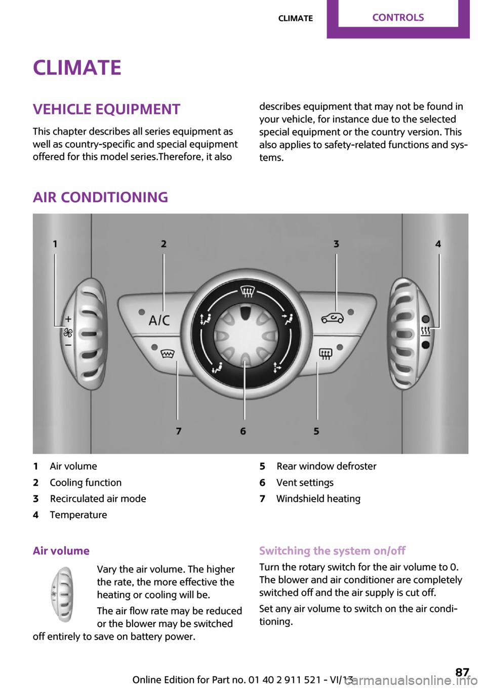
Air conditioning
1Air volume2Cooling function3Recirculated air mode4Temperature5Rear window defroster6Vent settings7Windshield heatingAir volume
Vary the air volume. The higher
the rate, the more effective the
heating or cooling will be.
The air flow rate may be reduced
or the blower may be switched
off entirely to save on battery power.Switching the system on/off
Turn the rotary switch for the air volume to 0.
The blower and air conditioner are completely switched off and the air supply is cut off.
Set any air volume to switch on the air condi‐
tioning.Seite 87ClimateControls87
Online Edition for Part no. 01 40 2 911 521 - VI/13