ECU MINI Countryman 2015 (Mini Connected) Owner's Guide
[x] Cancel search | Manufacturer: MINI, Model Year: 2015, Model line: Countryman, Model: MINI Countryman 2015Pages: 283, PDF Size: 6.76 MB
Page 128 of 283

Securing cargoLashing eyes in the cargo area
MINI Countryman
MINI Paceman
Securing cargo
▷Secure smaller and lighter pieces with tight‐
ening belts or straps.▷Secure larger and heavier pieces with cargo
straps.
Adhere to the information included with
the cargo straps.▷Eight mounting eyes are available for fas‐
tening the cargo straps.
Two of them are located on the side wall of
the cargo area, arrows 1, and two are lo‐
cated on the rear wall of the cargo area, ar‐
rows 2.Securing cargo
Stow and secure the cargo as described
above; otherwise it may present a danger to
the occupants, for instance during braking and
avoidance maneuvers.
Do not stow any heavy and hard objects in the
passenger compartment without securing
them; otherwise, they may present a danger to
occupants, for instance during braking and
avoidance maneuvers.
Never exceed either the approved gross vehicle
weight or either of the approved axle loads, as
excessive loads can pose a safety hazard, and
may also place you in violation of traffic safety
laws.
Do not secure cargo using the upper LATCH
mounting points, refer to page 54; otherwise,
these may become damaged. ◀
Roof-mounted luggage
rack
NotesA special rack system is available as an optionalaccessory.
Attachment Follow the installation instructions for the roof-
mounted luggage rack.
Ensure that adequate clearance is available for
the movement of the glass sunroof.
Loading Because roof racks raise the vehicle's center of
gravity when loaded, they have a major effect
on vehicle handling and steering response.
Therefore, note the following when loading and
driving:▷Do not exceed the approved roof/axle
loads and the approved gross vehicle
weight.Seite 126DRIVING TIPSLoading126
Online Edition for Part no. 01 40 2 961 110 - II/15
Page 129 of 283
▷Distribute the roof load uniformly.▷The roof load should not be too large in
area.▷Always load the heaviest pieces on the bot‐
tom.▷Fasten the roof-mounted luggage securely,
for instance using lashing straps.▷Do not let objects project into the opening
path of the tailgate.▷Drive smoothly. Avoid sudden acceleration
and braking maneuvers. Take corners gen‐
tly.
Rear luggage rack
Notes A special rear rack is available as an optional
accessory. It does not require a trailer hitch.
Follow the installation instructions for the rear
rack.
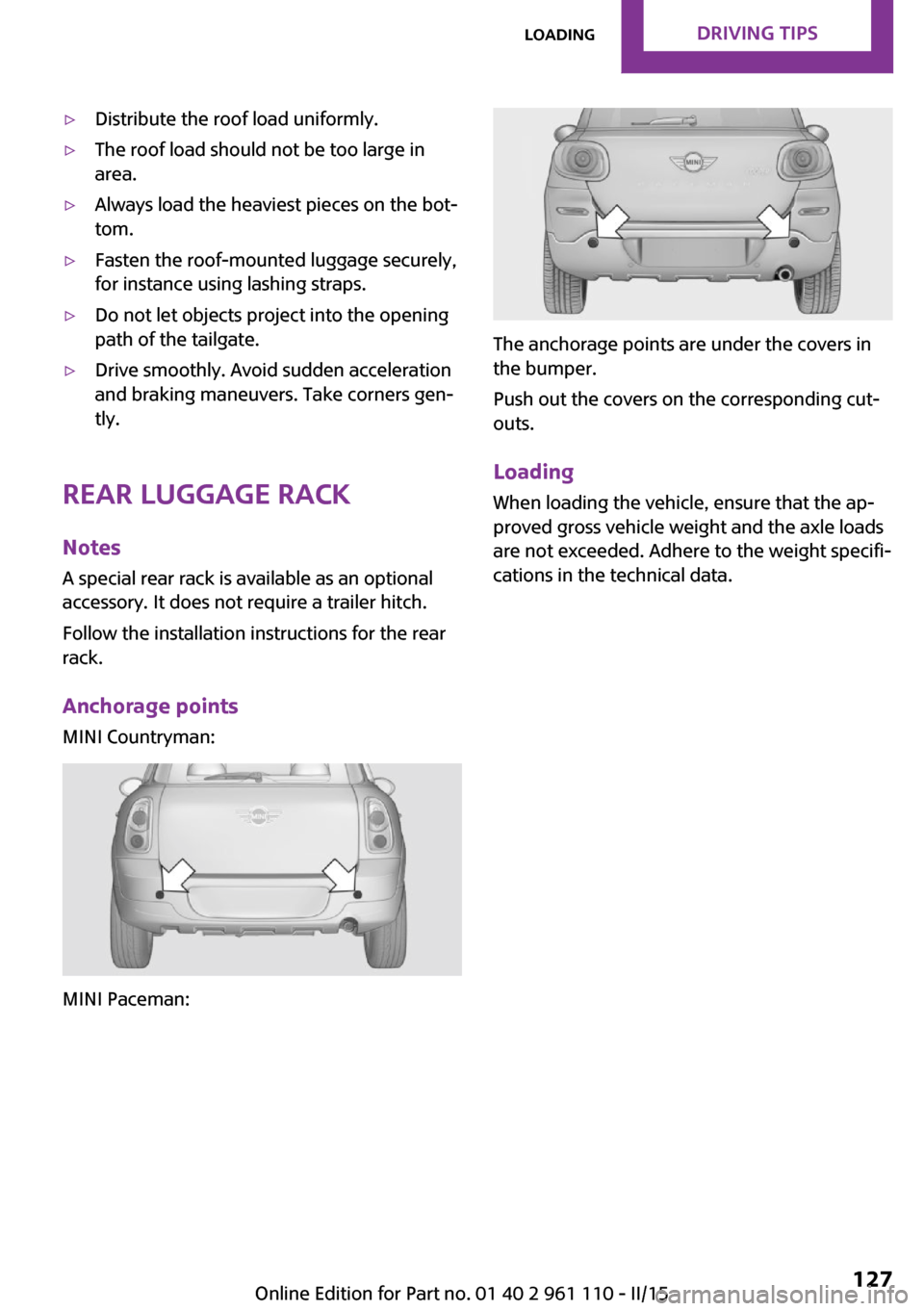
Anchorage points
MINI Countryman:
MINI Paceman:
The anchorage points are under the covers in
the bumper.
Push out the covers on the corresponding cut‐
outs.
Loading
When loading the vehicle, ensure that the ap‐
proved gross vehicle weight and the axle loads
are not exceeded. Adhere to the weight specifi‐
cations in the technical data.
Seite 127LoadingDRIVING TIPS127
Online Edition for Part no. 01 40 2 961 110 - II/15
Page 180 of 283
Bluetooth hands-free systemVehicle equipmentThis chapter describes all series equipment as
well as country-specific and special equipment
offered for this model series. Therefore, it also
describes equipment that may not be found in
your vehicle, for instance due to the selected
special equipment or the country version. This
also applies to safety-related functions and sys‐
tems.
When using the features and systems described
here, adhere to local regulations.
At a glance
The concept
Mobile phones can be connected with the vehi‐
cle via Bluetooth.
Bluetooth® is a registered trademark of Blue‐
tooth® SIG, Inc.
After these devices are paired once, they are
recognized automatically when the ignition is
switched on as soon as they are in the vehicle
and can then be operated via the onboard
monitor, using the buttons on the steering
wheel, and via voice activation.
Up to four external devices can be paired.
Certain functions may need to be enabled by
the mobile phone provider or service provider.
Using the mobile phone while driving
Make entries only when traffic and road
conditions allow. Do not hold the mobile phone
in your hand while you are driving; use the
hands-free system instead. If you do not ob‐
serve this precaution, you can endanger the ve‐
hicle occupants and other road users. ◀Approved mobile phones
Details on which mobile phones are supported
by the hands-free system can be obtained at
www.mini.com/connectivity.
Displaying the vehicle identification
number and software part number
The vehicle identification number and software
part number are needed to determine which
mobile phones are supported by the mobile
phone preparation package. The software ver‐
sion of the mobile phone may also be required.1."Telephone"2.Open "Options".3."Bluetooth® info"4."Display system information"
These approved mobile phones with a certain
software version, support the vehicle functions
described below.
Malfunctions may occur with other mobile
phones or software versions.
Do not operate a mobile phone that is con‐
nected to the vehicle on the mobile phone key‐
pad, as this may lead to a malfunction.
Notes
At high temperatures, the charging function of
the mobile phone may be limited and functions
may not be executed.
When using the mobile phone via the vehicle,
note the operating instructions of the mobile phone.
Seite 178COMMUNICATIONBluetooth hands-free system178
Online Edition for Part no. 01 40 2 961 110 - II/15
Page 191 of 283
Do not operate a mobile phone that is con‐
nected to the vehicle on the mobile phone key‐
pad, as this may lead to a malfunction.
Notes
At high temperatures, the charging function of
the mobile phone may be limited and functions
may not be executed.
When using the mobile phone via the vehicle,
note the operating instructions of the mobile
phone.
Pairing/unpairing the
mobile phone
General information The following functions are available:▷Use of a mobile phone as a telephone.▷Use of a mobile phone as an additional te‐
lephone.▷Use of a mobile phone as an audio source.▷Use of an audio device as an audio source,
refer to page 171.
Requirements
▷The mobile phone is suitable, refer to
page 188.▷The mobile phone is ready for operation.▷Bluetooth is activated in the vehicle and on
the mobile phone.▷Bluetooth presettings may need to be
made on the mobile phone, e.g., for a con‐
nection without confirmation or visibility,
refer to the mobile phone operating in‐
structions.▷Deactivate Bluetooth audio if necessary.▷Compare the control number on the Control
Display with the control number on the mo‐
bile phone display. Confirm the control
number on the mobile phone and in the
vehicle.▷A number with at least four and a maxi‐
mum of 16 digits was defined as the Blue‐
tooth passkey. It is only required once for
pairing.▷The radio ready state is switched on.
Activating/deactivating Bluetooth
Bluetooth is not permitted everywhere. Comply
with all safety guidelines and regulations.
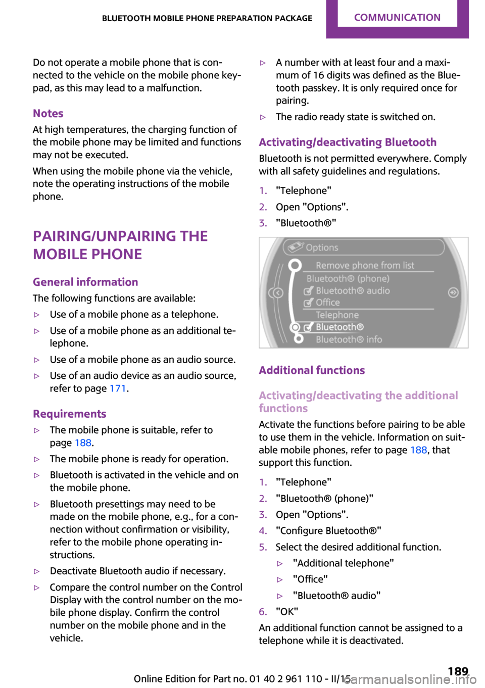
1."Telephone"2.Open "Options".3."Bluetooth®"
Additional functions
Activating/deactivating the additional functions
Activate the functions before pairing to be able
to use them in the vehicle. Information on suit‐
able mobile phones, refer to page 188, that
support this function.
1."Telephone"2."Bluetooth® (phone)"3.Open "Options".4."Configure Bluetooth®"5.Select the desired additional function.▷"Additional telephone"▷"Office"▷"Bluetooth® audio"6."OK"
An additional function cannot be assigned to a
telephone while it is deactivated.
Seite 189Bluetooth mobile phone preparation packageCOMMUNICATION189
Online Edition for Part no. 01 40 2 961 110 - II/15
Page 200 of 283
Snap-in adapter
General information More information on compatible snap-in
adapters that support the functions of the mo‐
bile phone is available at the service center.
Notes At high temperatures, the charging function of
the mobile phone may be limited and functions
may not be executed.
When using the mobile phone via the vehicle,
note the operating instructions of the mobile
phone.
Installation position In the center armrest.
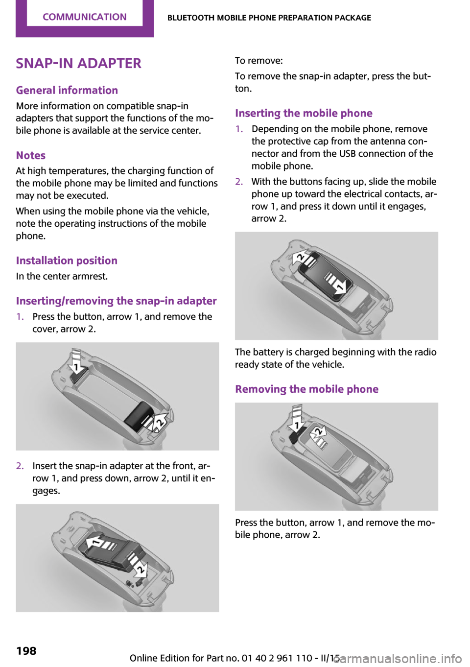
Inserting/removing the snap-in adapter1.Press the button, arrow 1, and remove the
cover, arrow 2.2.Insert the snap-in adapter at the front, ar‐
row 1, and press down, arrow 2, until it en‐
gages.To remove:
To remove the snap-in adapter, press the but‐
ton.
Inserting the mobile phone1.Depending on the mobile phone, remove
the protective cap from the antenna con‐
nector and from the USB connection of the
mobile phone.2.With the buttons facing up, slide the mobile
phone up toward the electrical contacts, ar‐
row 1, and press it down until it engages,
arrow 2.
The battery is charged beginning with the radio
ready state of the vehicle.
Removing the mobile phone
Press the button, arrow 1, and remove the mo‐
bile phone, arrow 2.
Seite 198COMMUNICATIONBluetooth mobile phone preparation package198
Online Edition for Part no. 01 40 2 961 110 - II/15
Page 231 of 283

Hood
Notes Working in the engine compartment
Never attempt to perform any service or
repair operations on your vehicle without the
necessary professional technical training.
If you are unfamiliar with the statutory guide‐
lines, have any work on the vehicle performed
only by a service center.
If this work is not carried out properly, there is
the danger of subsequent damage and related
safety hazards. ◀
To avoid damage, make sure that the
wiper arms are resting against the wind‐
shield before you open the engine compart‐
ment. Do not open the engine hood before the
engine has cooled down; otherwise, injuries
may result. ◀
Unlocking and opening the hood1.Pull the lever.2.Lift the hood all the way.3.Press the release handle and open the
hood.
Danger of injury when the hood is open
There is a danger of injury from protrud‐
ing parts when the hood is open. ◀
Closing the hood
Close the hood from a height of ap‐
prox. 16 in/40 cm with momentum. It must be
clearly heard to engage.
Hood open when driving
If you see any signs that the hood is not
completely closed while driving, pull over im‐
mediately and close it securely. ◀
Danger of pinching
Make sure that the closing path of the
hood is clear; otherwise, injuries may result. ◀
Seite 229Engine compartmentMOBILITY229
Online Edition for Part no. 01 40 2 961 110 - II/15
Page 245 of 283
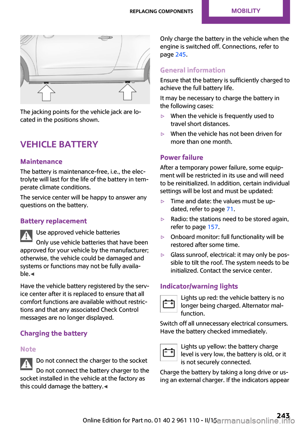
The jacking points for the vehicle jack are lo‐
cated in the positions shown.
Vehicle battery Maintenance
The battery is maintenance-free, i.e., the elec‐
trolyte will last for the life of the battery in tem‐
perate climate conditions.
The service center will be happy to answer any
questions on the battery.
Battery replacement Use approved vehicle batteries
Only use vehicle batteries that have been
approved for your vehicle by the manufacturer;
otherwise, the vehicle could be damaged and
systems or functions may not be fully availa‐
ble. ◀
Have the vehicle battery registered by the serv‐
ice center after it is replaced to ensure that all
comfort functions are available without restric‐
tions and that any associated Check Control
messages are no longer displayed.
Charging the battery
Note Do not connect the charger to the socket
Do not connect the battery charger to the
socket installed in the vehicle at the factory as this could damage the battery. ◀
Only charge the battery in the vehicle when the
engine is switched off. Connections, refer to
page 245.
General information Ensure that the battery is sufficiently charged to
achieve the full battery life.
It may be necessary to charge the battery in
the following cases:▷When the vehicle is frequently used to
travel short distances.▷When the vehicle has not been driven for
more than one month.
Power failure
After a temporary power failure, some equip‐
ment will be restricted in its use and will need
to be reinitialized. In addition, certain individual
settings will be lost and must be updated:
▷Time and date: the values must be up‐
dated, refer to page 71.▷Radio: the stations need to be stored again,
refer to page 157.▷Onboard monitor: full functionality will be
restored after some time.▷Glass sunroof, electrical: it may only be pos‐
sible to tilt the roof. The system needs to be
initialized. Contact the service center.
Indicator/warning lights
Lights up red: the vehicle battery is nolonger being charged. Alternator mal‐function.
Switch off all unnecessary electrical consumers.
Have the battery checked immediately.
Lights up yellow: the battery charge
level is very low, the battery is old, or it
is not securely connected.
Charge the battery by taking a long drive or us‐
ing an external charger. If the indicators appear
Seite 243Replacing componentsMOBILITY243
Online Edition for Part no. 01 40 2 961 110 - II/15
Page 246 of 283

again, have the battery checked as soon as
possible.
Disposing of old batteries Have used batteries disposed of by the
service center after they are replaced or
take them to a recycling center.
Maintain the battery in an upright position for
transport and storage. Secure the battery so
that it does not tip over during transport.
Fuses Replacing fuses
Never attempt to repair a blown fuse and
do not replace a defective fuse with a substi‐
tute of another color or amperage rating; this
could lead to a circuit overload, ultimately re‐
sulting in a fire in the vehicle. ◀
Fuses should be replaced by the service center.
Information on the fuses can be found on the
inside of the covers.
In the engine compartment
Opening the cover
Press the snap lock.
In interior
On the right side of the footwell.
Opening the cover
Push out at the recess.
Seite 244MOBILITYReplacing components244
Online Edition for Part no. 01 40 2 961 110 - II/15
Page 250 of 283
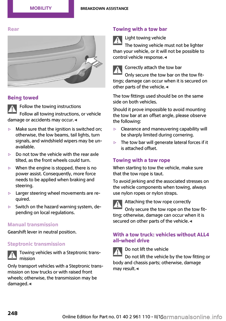
Rear
Being towedFollow the towing instructions
Follow all towing instructions, or vehicle
damage or accidents may occur. ◀
▷Make sure that the ignition is switched on;
otherwise, the low beams, tail lights, turn
signals, and windshield wipers may be un‐
available.▷Do not tow the vehicle with the rear axle
tilted, as the front wheels could turn.▷When the engine is stopped, there is no
power assist. Consequently, more force
needs to be applied when braking and
steering.▷Larger steering wheel movements are re‐
quired.▷Switch on the hazard warning system, de‐
pending on local regulations.
Manual transmission
Gearshift lever in neutral position.
Steptronic transmission Towing vehicles with a Steptronic trans‐
mission
Only transport vehicles with a Steptronic trans‐
mission on tow trucks or with raised front
wheels; otherwise, the transmission may be
damaged. ◀
Towing with a tow bar
Light towing vehicle
The towing vehicle must not be lighter
than your vehicle, or it will not be possible to
control vehicle response. ◀
Correctly attach the tow bar
Only secure the tow bar on the tow fit‐
tings; damage can occur when it is secured on
other parts of the vehicle. ◀
The tow fittings used should be on the same
side on both vehicles.
Should it prove impossible to avoid mounting
the tow bar at an offset angle, please observe
the following:▷Clearance and maneuvering capability will
be sharply limited during cornering.▷The tow bar will generate lateral forces if it
is attached offset.
Towing with a tow rope
When starting to tow the vehicle, make sure
that the tow rope is taut.
To avoid jerking and the associated stresses on
the vehicle components when towing, always
use nylon ropes or nylon straps.
Attaching the tow rope correctly
Only secure the tow rope on the tow fit‐
ting; otherwise, damage can occur when it is
secured on other parts of the vehicle. ◀
With a tow truck: vehicles without ALL4
all-wheel drive
Do not lift the vehicle
Do not lift the vehicle by the tow fitting or
body and chassis parts; otherwise, damage
may result. ◀
Seite 248MOBILITYBreakdown assistance248
Online Edition for Part no. 01 40 2 961 110 - II/15
Page 255 of 283
grease removers, fuel, or such; this could lead
to surface damage. ◀
Rubber seals Only treat with water or a rubber care product.
When cleaning rubber seals, do not use silicone
sprays or other care products containing sili‐
cone; otherwise, noise and damage may result.
Chrome surfaces
Carefully clean components such as the radia‐
tor grille or door handles with an ample supply
of water, possibly with shampoo added, partic‐
ularly when they have been exposed to road
salt. For additional treatment, use a chrome
polish.
Light-alloy wheels
When cleaning the wheels on the vehicle, only
use a neutral wheel rim cleaner with a pH value
of 5 to 9.
Do not use abrasive cleaners or a steam jet hot‐
ter than 140 ℉/60 ℃; otherwise, damage may
result. Adhere to the manufacturer instructions.
Aggressive, acidic, or alkaline cleaners may de‐
stroy the protective coating of neighboring
components such as the brake disc.
Exterior sensors
The sensors on the outside of the vehicle, such
as for Park Distance Control, must be kept clean
and free of ice to ensure that they remain fully
functional.
Decorative trim
Clean decorative trims and fine wood compo‐
nents with a moist cloth only. Then dry with a
soft cloth.
Safety belts Dirty belt straps impede the reeling action and
thus have a negative impact on safety.No chemical cleaning
Do not clean chemically; this can destroy
the webbing. ◀
Carpets/floor mats No objects in the area around the pedals
Keep floor mats, carpets, and any other
objects out of the area of motion of the pedals;
otherwise, the function of the pedals could be
impeded while driving
Do not place additional floor mats over existing
mats or other objects.
Only use floor mats that have been approved
for the vehicle and can be properly fixed in
place.
Ensure that the floor mats are securely fastened
again when they are returned after being re‐
moved, such as for cleaning. ◀
Floor mats can be removed for cleaning.
If they are very dirty, clean with a microfiber
cloth and water or an interior cleaner. To pre‐
vent matting of the carpet, rub back and forth
in the direction of travel only.
Displays To clean the displays, such as the radio or dis‐
play elements, use an antistatic microfiber
cloth.
Cleaning displays
Do not use chemical or household cleans‐
ers.
Keep all fluids and moisture away from the
unit.
Otherwise, they could affect or damage surfa‐
ces or electrical components.
Avoid pressing too hard when cleaning and do
not use abrasive materials; otherwise, damage
can result. ◀Seite 253CareMOBILITY253
Online Edition for Part no. 01 40 2 961 110 - II/15