display MINI Countryman 2015 (Mini Connected) Owner's Guide
[x] Cancel search | Manufacturer: MINI, Model Year: 2015, Model line: Countryman, Model: MINI Countryman 2015Pages: 283, PDF Size: 6.76 MB
Page 64 of 283
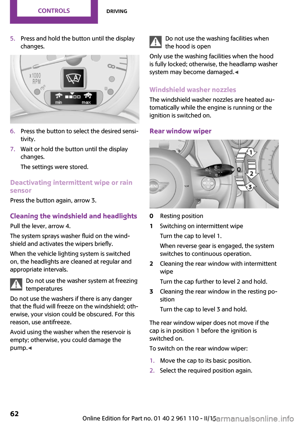
5.Press and hold the button until the display
changes.6.Press the button to select the desired sensi‐
tivity.7.Wait or hold the button until the display
changes.
The settings were stored.
Deactivating intermittent wipe or rain
sensor
Press the button again, arrow 3.
Cleaning the windshield and headlights
Pull the lever, arrow 4.
The system sprays washer fluid on the wind‐
shield and activates the wipers briefly.
When the vehicle lighting system is switched
on, the headlights are cleaned at regular and
appropriate intervals.
Do not use the washer system at freezing
temperatures
Do not use the washers if there is any danger
that the fluid will freeze on the windshield; oth‐
erwise, your vision could be obscured. For this
reason, use antifreeze.
Avoid using the washer when the reservoir is
empty; otherwise, you could damage the
pump. ◀
Do not use the washing facilities when
the hood is open
Only use the washing facilities when the hood
is fully locked; otherwise, the headlamp washer
system may become damaged. ◀
Windshield washer nozzles The windshield washer nozzles are heated au‐
tomatically while the engine is running or the
ignition is switched on.
Rear window wiper0Resting position1Switching on intermittent wipe
Turn the cap to level 1.
When reverse gear is engaged, the system
switches to continuous operation.2Cleaning the rear window with intermittent
wipe
Turn the cap further to level 2 and hold.3Cleaning the rear window in the resting po‐
sition
Turn the cap to level 3 and hold.
The rear window wiper does not move if the
cap is in position 1 before the ignition is
switched on.
To switch on the rear window wiper:
1.Move the cap to its basic position.2.Select the required position again.Seite 62CONTROLSDriving62
Online Edition for Part no. 01 40 2 961 110 - II/15
Page 66 of 283
Reverse gearSelect only when the vehicle is stationary. When
the gearshift lever is pressed to the left, a slight
resistance needs to be overcome.
Steptronic transmission In addition to the fully automatic mode, gears
can also be shifted manually using Steptronic,
refer to page 65.
Parking the vehicle Secure the vehicle
Before leaving the vehicle with the en‐
gine running, move the selector lever to posi‐
tion P and set the handbrake; otherwise, the
vehicle will begin moving. ◀
Disengaging the remote control
To remove the remote control from the ignition
lock, first move the selector lever to position P
and switch off the engine: interlock. Remove
the remote control from the ignition lock, refer
to page 57.
Selector lever positions
P R N D M/S + –
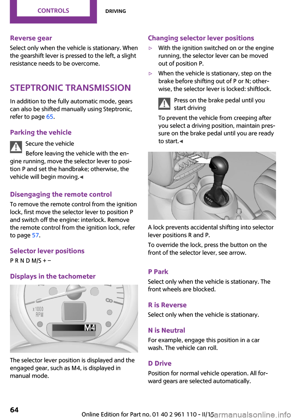
Displays in the tachometer
The selector lever position is displayed and the
engaged gear, such as M4, is displayed in
manual mode.
Changing selector lever positions▷With the ignition switched on or the engine
running, the selector lever can be moved
out of position P.▷When the vehicle is stationary, step on the
brake before shifting out of P or N; other‐
wise, the selector lever is locked: shiftlock.
Press on the brake pedal until you
start driving
To prevent the vehicle from creeping after
you select a driving position, maintain pres‐
sure on the brake pedal until you are ready
to start. ◀
A lock prevents accidental shifting into selector
lever positions R and P.
To override the lock, press the button on the
front of the selector lever, see arrow.
P Park
Select only when the vehicle is stationary. The
front wheels are blocked.
R is Reverse
Select only when the vehicle is stationary.
N is NeutralFor example, engage this position in a car
wash. The vehicle can roll.
D Drive Position for normal vehicle operation. All for‐
ward gears are selected automatically.
Seite 64CONTROLSDriving64
Online Edition for Part no. 01 40 2 961 110 - II/15
Page 67 of 283

Under normal operating conditions, fuel con‐
sumption is lowest when you are driving in po‐
sition D.
Kickdown
Kickdown is used to achieve maximum driving
performance. Press on the accelerator beyond
the resistance point at the full throttle position.
Sport program and manual mode M/S
Activating the Sport program
Move the selector lever from position D toward
the left into the M/S shifting slot.
The Sport program is activated and DS is dis‐
played. This position is recommended for a per‐
formance-oriented driving style.
To deactivate the Sport program or manual
mode M/S, move the selector lever to the right
into position D.
Activating the M/S manual mode Move the selector lever from position D towardthe left into the M/S shifting slot.
Push the selector lever forward or backward.
Manual mode becomes active and the gear is
changed.
The tachometer displays the engaged gear,
e. g. M1.
▷To shift up: press the selector lever back‐
ward.▷To shift down: press the selector lever for‐
ward.The vehicle only shifts up or down at appropri‐
ate engine and road speeds, e.g., it does not
shift down if the engine speed is too high. The
selected gear is briefly displayed in the instru‐
ment panel, followed by the current gear.
Shifting gears using the shift paddleson the steering wheel
The shift paddles on the steering wheel allow
you to shift gears quickly while keeping both hands on the steering wheel.▷When the shift paddles on the steering
wheel are used to shift gears while in auto‐
matic mode, the transmission switches to
manual mode.▷If the shift paddles are not used to acceler‐
ate or shift gears for a certain amount of
time, the transmission switches back to au‐
tomatic mode.
If the selector lever is in the M/S gear plane,
manual mode remains active.
▷Pull one of the two shift paddles:
The transmission shifts up.▷Press one of the two shift paddles:
The transmission shifts down.
The vehicle only shifts up or down at appropri‐
ate engine and road speeds, e.g., it does not
shift down if the engine speed is too high. The
selected gear is briefly displayed in the instru‐
ment panel, followed by the current gear.
Seite 65DrivingCONTROLS65
Online Edition for Part no. 01 40 2 961 110 - II/15
Page 69 of 283

DisplaysVehicle equipment
This chapter describes all series equipment as
well as country-specific and special equipment
offered for this model series. Therefore, it also
describes equipment that may not be found in
your vehicle, for instance due to the selected
special equipment or the country version. This
also applies to safety-related functions and sys‐
tems.
When using the features and systems described
here, adhere to local regulations.
Odometer, external tem‐
perature display, clock
At a glance1Current speed2Odometer, trip odometer, external temper‐
ature, time3Resetting the trip odometer
Press the button on the turn indicator lever to
open information in display area 2.
The following information is displayed consecu‐
tively:
▷Trip odometer▷Time▷External temperatureTrip odometer
Displaying the trip odometer Press button 3 briefly.
Resetting the trip odometer1.Press button 3 briefly.
The trip odometer is displayed.2.Press button 3 again.
The trip odometer is reset.
Time
Set the time, refer to page 71.
External temperature, external
temperature warning
If the display drops to +37 ℉/+3 ℃, a signal
sounds and a warning light lights up. There is
the increased danger of ice.
Ice on roads
Even at temperatures above
+37 ℉/+3 ℃, there can be a risk of ice on
roads.
Therefore, drive carefully on bridges and shady
roads, for example, to avoid the increased dan‐
ger of an accident. ◀
Units of measure To set the respective units of measure, miles or
km for the odometer and ℃ or ℉ for the exter‐
nal temperature, refer to page 71.
Seite 67DisplaysCONTROLS67
Online Edition for Part no. 01 40 2 961 110 - II/15
Page 70 of 283

Tachometer
It is imperative that you avoid engine speeds in
the red warning field. In this range, the fuel
supply is interrupted to protect the engine.
Coolant temperature A warning lamp will come on if the coolant, and
therefore the engine, becomes too hot. In addi‐
tion, a message will appear on the Control Dis‐
play.
Check the coolant level, refer to page 232.
Fuel gauge
The arrow next to the fuel pump symbol on the
fuel gauge indicates the side of the vehicle with
the fuel filler flap.
The vehicle inclination may cause the display to
vary.
Notes on refueling, refer to page 212.
Filling capacities, refer to page 261.
Range
After the reserve range is reached:▷The remaining LEDs change from orange to
red, arrow.▷A message is briefly displayed on the Con‐
trol Display.▷The remaining range is shown on the tach‐
ometer.▷When a dynamic driving style is used, such
as when corners are taken rapidly, engine
functions are not ensured.
The message appears continuously below a
range of approx. 30 miles/50 km.
Refuel promptly
At the latest, refuel at a range below
30 miles/50 km; otherwise, the engine function
is not ensured and damage may occur. ◀
Computer
Opening information in the tachometer
Press the button on the turn indicator lever.
Overview of the information
The following information is displayed consecu‐
tively by repeatedly pressing the button on the
turn indicator lever:
▷Range.▷Average fuel consumption.▷Current fuel consumption.▷Average speed.Seite 68CONTROLSDisplays68
Online Edition for Part no. 01 40 2 961 110 - II/15
Page 71 of 283
To set the corresponding units of measure, re‐
fer to page 71.
Information in detail
Range
Displays the estimated cruising range available
with the remaining fuel.
It is calculated based on your driving style over
the last 18 miles/30 km.
Average fuel consumption
This is calculated for the period during which
the engine is running.
With the trip computer, refer to page 69, the
average consumption can be displayed for an
additional distance.
To reset the average consumption: press the
button on the turn indicator lever for ap‐
prox. 2 seconds.
Current fuel consumption Displays the current fuel consumption. You can
check whether you are currently driving in an
efficient and environmentally-friendly manner.
Average speed Periods in which the vehicle was parked and
the engine was switched off manually are not
included in the average speed calculations.
With the trip computer, refer to page 69, the
average speed can be displayed for an addi‐
tional distance.
To reset the average speed: press the button
on the turn indicator lever for approx. 2 sec‐
onds.
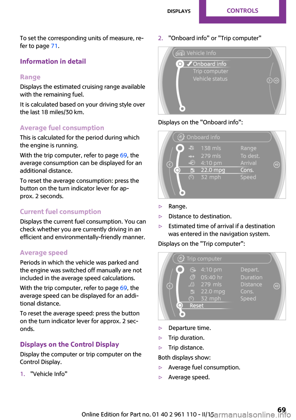
Displays on the Control Display Display the computer or trip computer on the
Control Display.1."Vehicle Info"2."Onboard info" or "Trip computer"
Displays on the "Onboard info":
▷Range.▷Distance to destination.▷Estimated time of arrival if a destination
was entered in the navigation system.
Displays on the "Trip computer":
▷Departure time.▷Trip duration.▷Trip distance.
Both displays show:
▷Average fuel consumption.▷Average speed.Seite 69DisplaysCONTROLS69
Online Edition for Part no. 01 40 2 961 110 - II/15
Page 72 of 283
Resetting the fuel consumption and
speed
Resetting the values for average speed and
average fuel consumption:1.Select the respective menu item and press
the MINI joystick.2.Press the MINI joystick again to confirm
your selection.
Resetting the trip computer
Resetting all values:
1."Vehicle Info"2."Trip computer"3."Reset"
Settings and information
Operating concept
Some settings and information can only be cre‐
ated or opened while the ignition is switched
on, the vehicle is standing, and the doors are
closed.
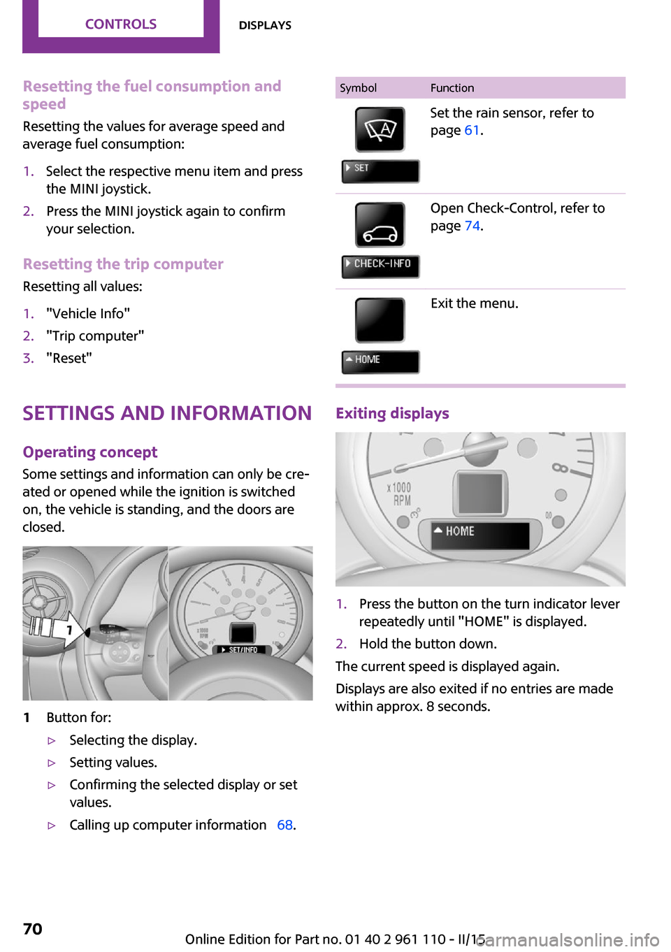
1Button for:▷Selecting the display.▷Setting values.▷Confirming the selected display or set
values.▷Calling up computer information 68.SymbolFunctionSet the rain sensor, refer to
page 61.Open Check-Control, refer to
page 74.Exit the menu.
Exiting displays
1.Press the button on the turn indicator lever
repeatedly until "HOME" is displayed.2.Hold the button down.
The current speed is displayed again.
Displays are also exited if no entries are made
within approx. 8 seconds.
Seite 70CONTROLSDisplays70
Online Edition for Part no. 01 40 2 961 110 - II/15
Page 73 of 283
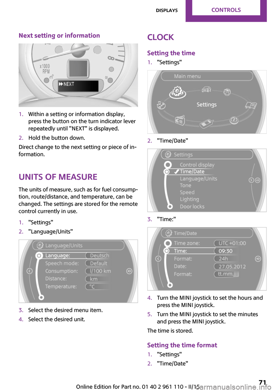
Next setting or information1.Within a setting or information display,
press the button on the turn indicator lever
repeatedly until "NEXT" is displayed.2.Hold the button down.
Direct change to the next setting or piece of in‐
formation.
Units of measure
The units of measure, such as for fuel consump‐
tion, route/distance, and temperature, can be
changed. The settings are stored for the remote
control currently in use.
1."Settings"2."Language/Units"3.Select the desired menu item.4.Select the desired unit.Clock
Setting the time1."Settings"2."Time/Date"3."Time:"4.Turn the MINI joystick to set the hours and
press the MINI joystick.5.Turn the MINI joystick to set the minutes
and press the MINI joystick.
The time is stored.
Setting the time format
1."Settings"2."Time/Date"Seite 71DisplaysCONTROLS71
Online Edition for Part no. 01 40 2 961 110 - II/15
Page 74 of 283
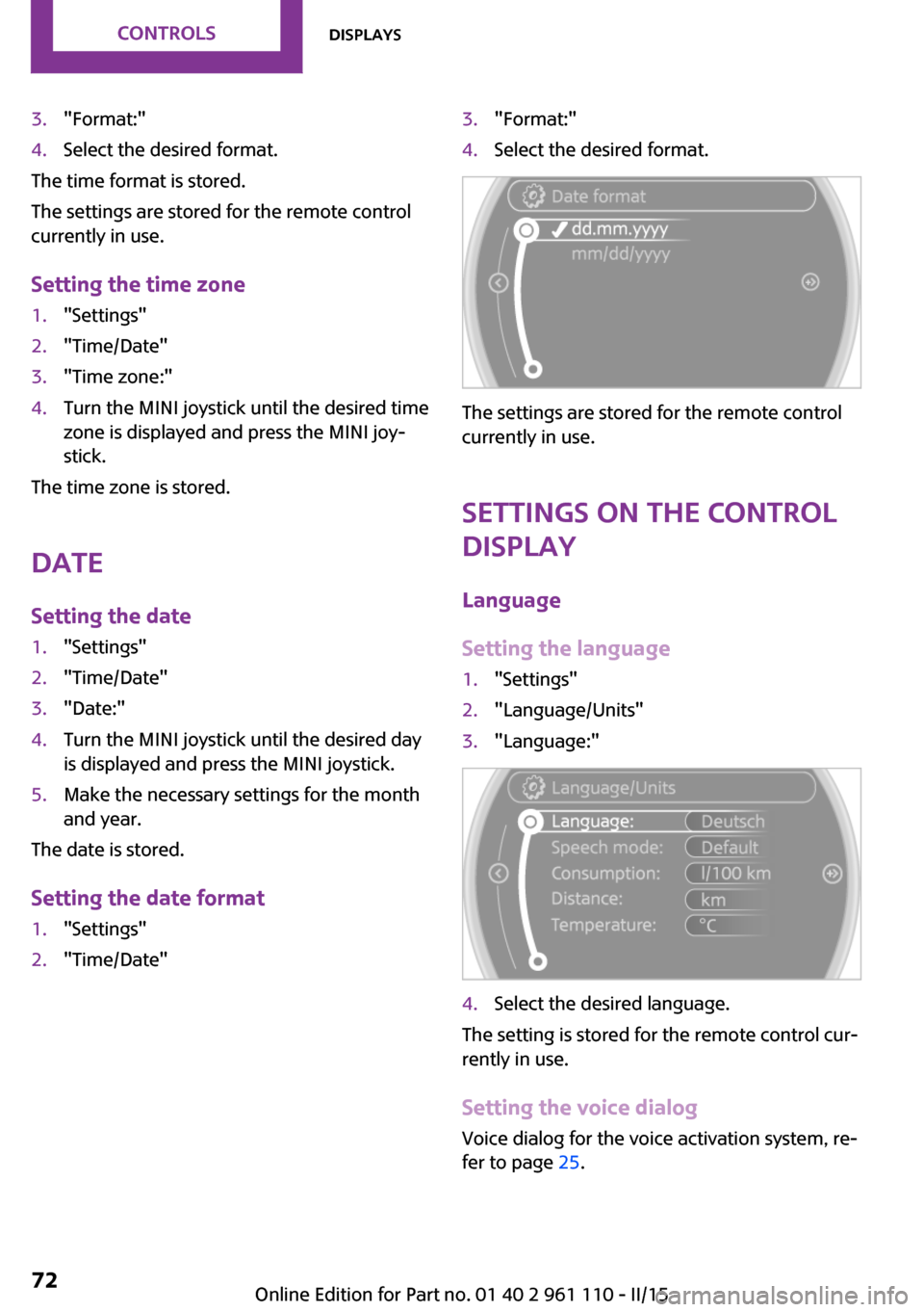
3."Format:"4.Select the desired format.
The time format is stored.
The settings are stored for the remote control
currently in use.
Setting the time zone
1."Settings"2."Time/Date"3."Time zone:"4.Turn the MINI joystick until the desired time
zone is displayed and press the MINI joy‐
stick.
The time zone is stored.
Date
Setting the date
1."Settings"2."Time/Date"3."Date:"4.Turn the MINI joystick until the desired day
is displayed and press the MINI joystick.5.Make the necessary settings for the month
and year.
The date is stored.
Setting the date format
1."Settings"2."Time/Date"3."Format:"4.Select the desired format.
The settings are stored for the remote control
currently in use.
Settings on the Control Display
Language
Setting the language
1."Settings"2."Language/Units"3."Language:"4.Select the desired language.
The setting is stored for the remote control cur‐
rently in use.
Setting the voice dialog Voice dialog for the voice activation system, re‐
fer to page 25.
Seite 72CONTROLSDisplays72
Online Edition for Part no. 01 40 2 961 110 - II/15
Page 75 of 283
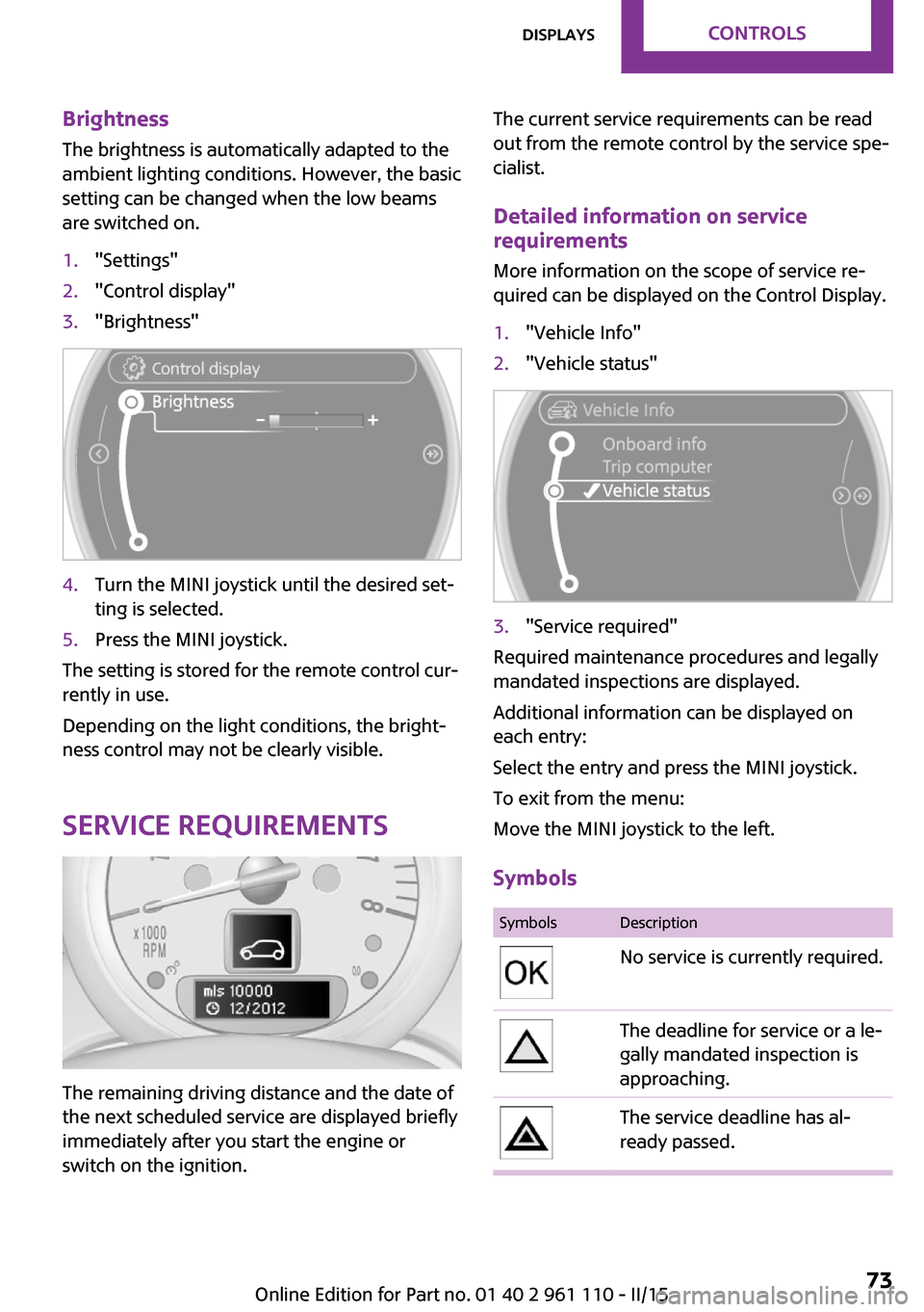
Brightness
The brightness is automatically adapted to the
ambient lighting conditions. However, the basic
setting can be changed when the low beams
are switched on.1."Settings"2."Control display"3."Brightness"4.Turn the MINI joystick until the desired set‐
ting is selected.5.Press the MINI joystick.
The setting is stored for the remote control cur‐
rently in use.
Depending on the light conditions, the bright‐
ness control may not be clearly visible.
Service requirements
The remaining driving distance and the date of
the next scheduled service are displayed briefly
immediately after you start the engine or
switch on the ignition.
The current service requirements can be read
out from the remote control by the service spe‐
cialist.
Detailed information on service
requirements
More information on the scope of service re‐
quired can be displayed on the Control Display.1."Vehicle Info"2."Vehicle status"3."Service required"
Required maintenance procedures and legally
mandated inspections are displayed.
Additional information can be displayed on
each entry:
Select the entry and press the MINI joystick.
To exit from the menu:
Move the MINI joystick to the left.
Symbols
SymbolsDescriptionNo service is currently required.The deadline for service or a le‐
gally mandated inspection is
approaching.The service deadline has al‐
ready passed.Seite 73DisplaysCONTROLS73
Online Edition for Part no. 01 40 2 961 110 - II/15