display MINI Countryman 2015 (Mini Connected) Owner's Guide
[x] Cancel search | Manufacturer: MINI, Model Year: 2015, Model line: Countryman, Model: MINI Countryman 2015Pages: 283, PDF Size: 6.76 MB
Page 76 of 283
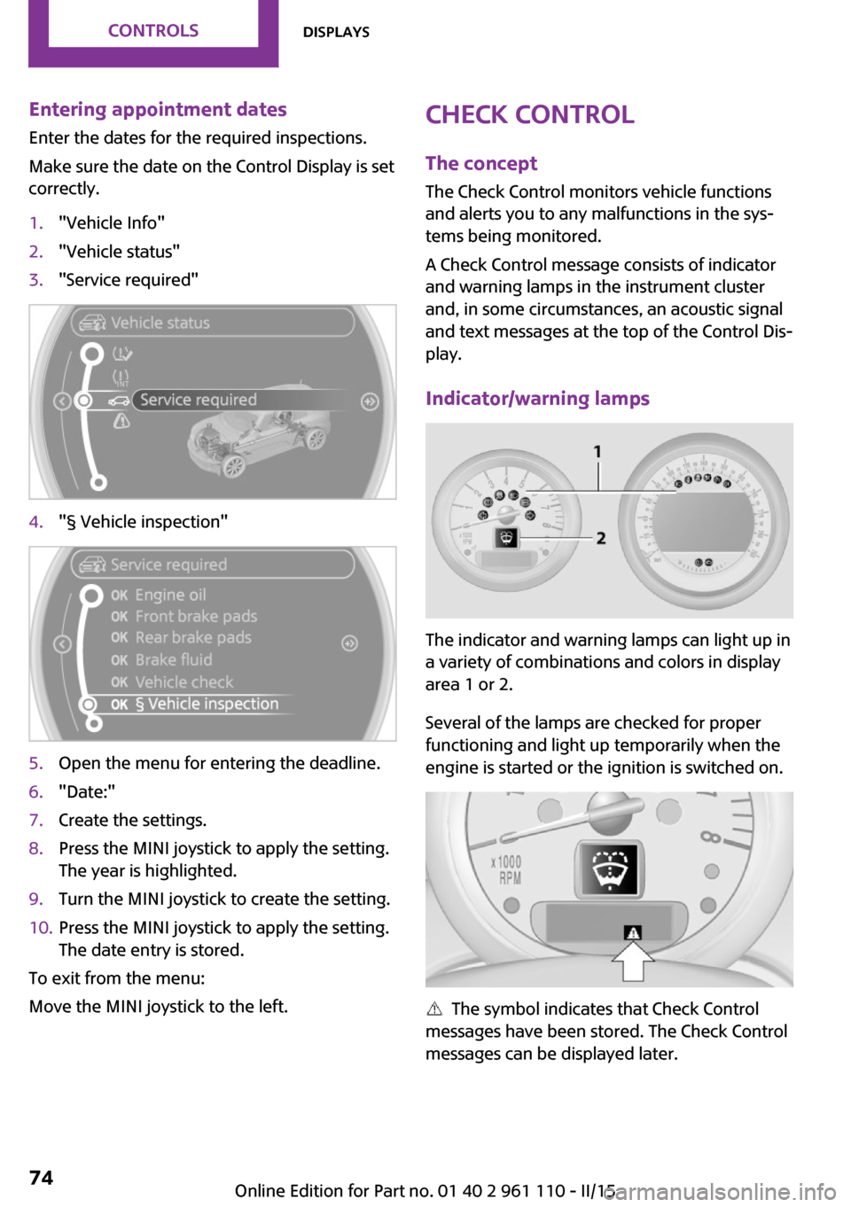
Entering appointment dates
Enter the dates for the required inspections.
Make sure the date on the Control Display is set
correctly.1."Vehicle Info"2."Vehicle status"3."Service required"4."§ Vehicle inspection"5.Open the menu for entering the deadline.6."Date:"7.Create the settings.8.Press the MINI joystick to apply the setting.
The year is highlighted.9.Turn the MINI joystick to create the setting.10.Press the MINI joystick to apply the setting.
The date entry is stored.
To exit from the menu:
Move the MINI joystick to the left.
Check Control
The concept
The Check Control monitors vehicle functions
and alerts you to any malfunctions in the sys‐
tems being monitored.
A Check Control message consists of indicator
and warning lamps in the instrument cluster
and, in some circumstances, an acoustic signal
and text messages at the top of the Control Dis‐
play.
Indicator/warning lamps
The indicator and warning lamps can light up in
a variety of combinations and colors in display
area 1 or 2.
Several of the lamps are checked for proper
functioning and light up temporarily when the
engine is started or the ignition is switched on.
The symbol indicates that Check Control
messages have been stored. The Check Control
messages can be displayed later.
Seite 74CONTROLSDisplays74
Online Edition for Part no. 01 40 2 961 110 - II/15
Page 77 of 283
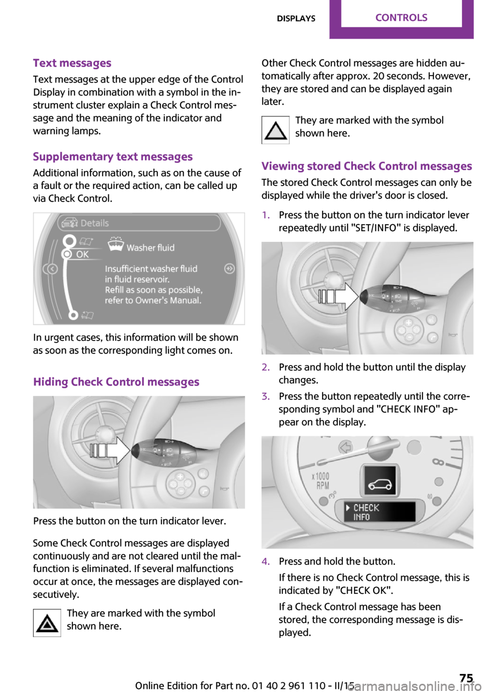
Text messages
Text messages at the upper edge of the Control
Display in combination with a symbol in the in‐
strument cluster explain a Check Control mes‐
sage and the meaning of the indicator and warning lamps.
Supplementary text messages Additional information, such as on the cause of
a fault or the required action, can be called up
via Check Control.
In urgent cases, this information will be shown
as soon as the corresponding light comes on.
Hiding Check Control messages
Press the button on the turn indicator lever.
Some Check Control messages are displayed
continuously and are not cleared until the mal‐
function is eliminated. If several malfunctions
occur at once, the messages are displayed con‐
secutively.
They are marked with the symbol
shown here.
Other Check Control messages are hidden au‐
tomatically after approx. 20 seconds. However,
they are stored and can be displayed again
later.
They are marked with the symbol
shown here.
Viewing stored Check Control messages The stored Check Control messages can only be
displayed while the driver's door is closed.1.Press the button on the turn indicator lever
repeatedly until "SET/INFO" is displayed.2.Press and hold the button until the display
changes.3.Press the button repeatedly until the corre‐
sponding symbol and "CHECK INFO" ap‐
pear on the display.4.Press and hold the button.
If there is no Check Control message, this is
indicated by "CHECK OK".
If a Check Control message has been
stored, the corresponding message is dis‐
played.Seite 75DisplaysCONTROLS75
Online Edition for Part no. 01 40 2 961 110 - II/15
Page 78 of 283
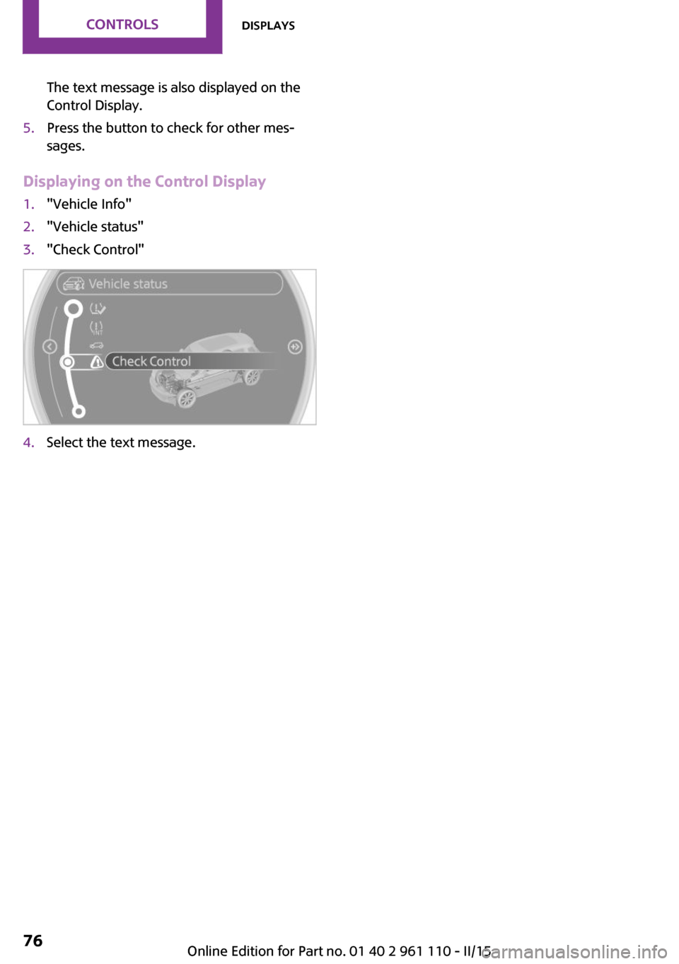
The text message is also displayed on the
Control Display.5.Press the button to check for other mes‐
sages.
Displaying on the Control Display
1."Vehicle Info"2."Vehicle status"3."Check Control"4.Select the text message.Seite 76CONTROLSDisplays76
Online Edition for Part no. 01 40 2 961 110 - II/15
Page 81 of 283
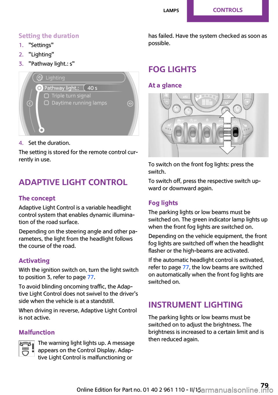
Setting the duration1."Settings"2."Lighting"3."Pathway light.: s"4.Set the duration.
The setting is stored for the remote control cur‐
rently in use.
Adaptive Light Control
The concept
Adaptive Light Control is a variable headlight
control system that enables dynamic illumina‐
tion of the road surface.
Depending on the steering angle and other pa‐
rameters, the light from the headlight follows
the course of the road.
Activating
With the ignition switch on, turn the light switch
to position 3, refer to page 77.
To avoid blinding oncoming traffic, the Adap‐
tive Light Control does not swivel to the driver's
side when the vehicle is at a standstill.
When driving in reverse, Adaptive Light Control
is not active.
Malfunction The warning light lights up. A message
appears on the Control Display. Adap‐
tive Light Control is malfunctioning or
has failed. Have the system checked as soon as
possible.
Fog lights At a glance
To switch on the front fog lights: press the
switch.
To switch off, press the respective switch up‐
ward or downward again.
Fog lights The parking lights or low beams must be
switched on. The green indicator lamp lights up
when the front fog lights are switched on.
Depending on the vehicle equipment, the front
fog lights are switched off when the headlight
flasher or the high-beams are activated.
If the automatic headlight control is activated,
refer to page 77, the low beams are switched
on automatically when the front fog lights are
switched on.
Instrument lighting The parking lights or low beams must be
switched on to adjust the brightness. The
brightness is increased to a certain limit and is then reduced again.
Seite 79LampsCONTROLS79
Online Edition for Part no. 01 40 2 961 110 - II/15
Page 86 of 283
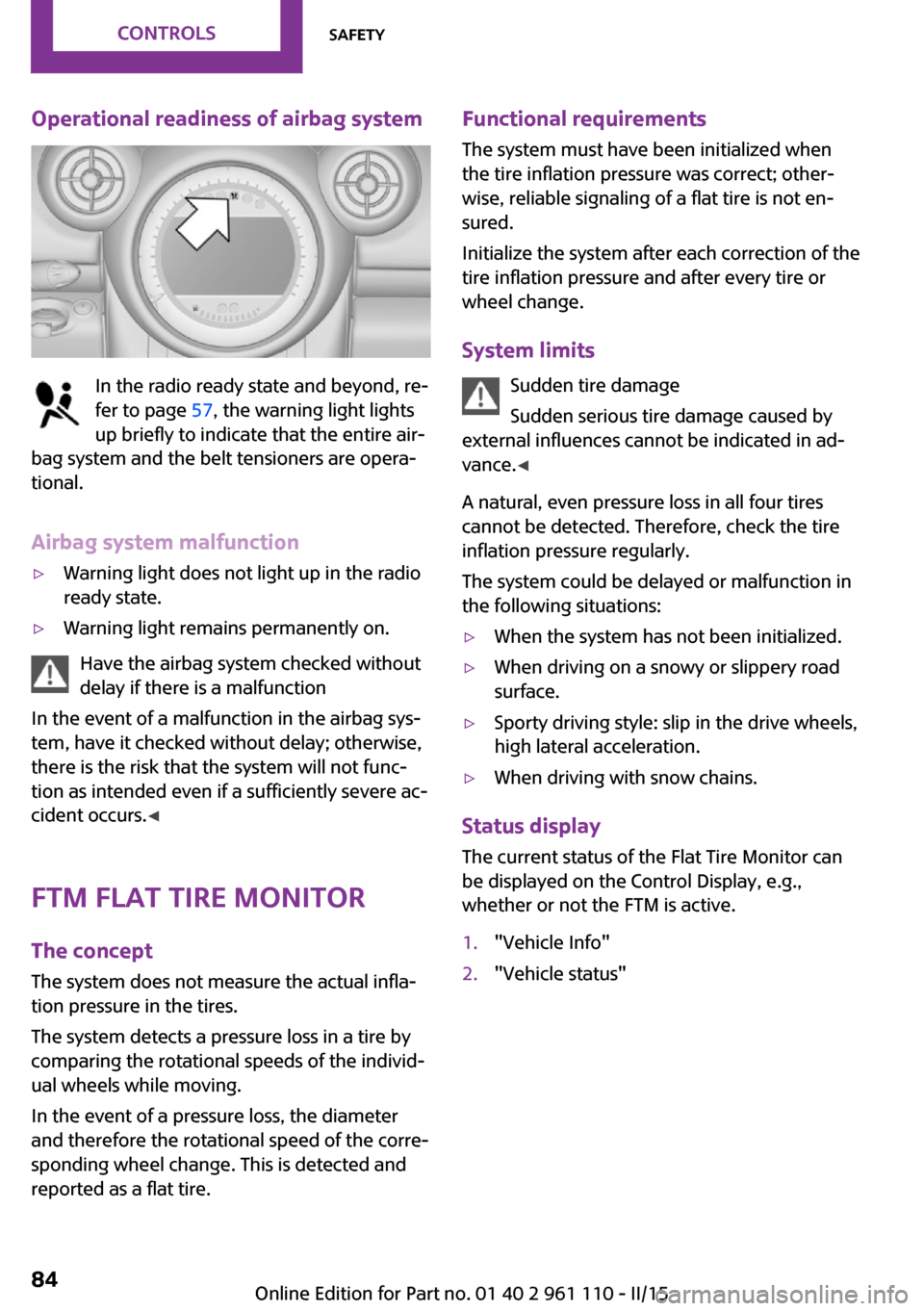
Operational readiness of airbag system
In the radio ready state and beyond, re‐
fer to page 57, the warning light lights
up briefly to indicate that the entire air‐
bag system and the belt tensioners are opera‐
tional.
Airbag system malfunction
▷Warning light does not light up in the radio
ready state.▷Warning light remains permanently on.
Have the airbag system checked without
delay if there is a malfunction
In the event of a malfunction in the airbag sys‐
tem, have it checked without delay; otherwise,
there is the risk that the system will not func‐
tion as intended even if a sufficiently severe ac‐
cident occurs. ◀
FTM Flat Tire Monitor The concept
The system does not measure the actual infla‐
tion pressure in the tires.
The system detects a pressure loss in a tire by
comparing the rotational speeds of the individ‐
ual wheels while moving.
In the event of a pressure loss, the diameter
and therefore the rotational speed of the corre‐
sponding wheel change. This is detected and
reported as a flat tire.
Functional requirements
The system must have been initialized when
the tire inflation pressure was correct; other‐
wise, reliable signaling of a flat tire is not en‐
sured.
Initialize the system after each correction of the
tire inflation pressure and after every tire or
wheel change.
System limits Sudden tire damage
Sudden serious tire damage caused by
external influences cannot be indicated in ad‐
vance. ◀
A natural, even pressure loss in all four tires
cannot be detected. Therefore, check the tire
inflation pressure regularly.
The system could be delayed or malfunction in
the following situations:▷When the system has not been initialized.▷When driving on a snowy or slippery road
surface.▷Sporty driving style: slip in the drive wheels,
high lateral acceleration.▷When driving with snow chains.
Status display
The current status of the Flat Tire Monitor can
be displayed on the Control Display, e.g.,
whether or not the FTM is active.
1."Vehicle Info"2."Vehicle status"Seite 84CONTROLSSafety84
Online Edition for Part no. 01 40 2 961 110 - II/15
Page 87 of 283
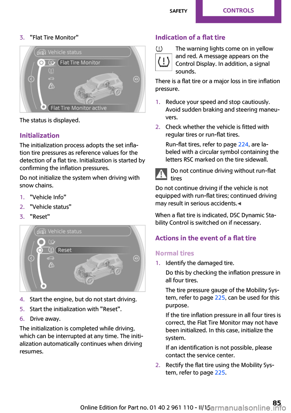
3."Flat Tire Monitor"
The status is displayed.
Initialization The initialization process adopts the set infla‐
tion tire pressures as reference values for the
detection of a flat tire. Initialization is started by
confirming the inflation pressures.
Do not initialize the system when driving with
snow chains.
1."Vehicle Info"2."Vehicle status"3."Reset"4.Start the engine, but do not start driving.5.Start the initialization with "Reset".6.Drive away.
The initialization is completed while driving,
which can be interrupted at any time. The initi‐
alization automatically continues when driving
resumes.
Indication of a flat tire
The warning lights come on in yellow
and red. A message appears on the
Control Display. In addition, a signal
sounds.
There is a flat tire or a major loss in tire inflation
pressure.1.Reduce your speed and stop cautiously.
Avoid sudden braking and steering maneu‐
vers.2.Check whether the vehicle is fitted with
regular tires or run-flat tires.
Run-flat tires, refer to page 224, are la‐
beled with a circular symbol containing the
letters RSC marked on the tire sidewall.
Do not continue driving without run-flat
tires
Do not continue driving if the vehicle is not
equipped with run-flat tires; continued driving
may result in serious accidents. ◀
When a flat tire is indicated, DSC Dynamic Sta‐
bility Control is switched on if necessary.
Actions in the event of a flat tire
Normal tires
1.Identify the damaged tire.
Do this by checking the inflation pressure in
all four tires.
The tire pressure gauge of the Mobility Sys‐
tem, refer to page 225, can be used for this
purpose.
If the tire inflation pressure in all four tires is
correct, the Flat Tire Monitor may not have
been initialized. In this case, initialize the
system.
If an identification is not possible, please
contact the service center.2.Rectify the flat tire using the Mobility Sys‐
tem, refer to page 225.Seite 85SafetyCONTROLS85
Online Edition for Part no. 01 40 2 961 110 - II/15
Page 89 of 283

Status displayThe current status of the Tire Pressure Monitor
TPM can be displayed on the Control Display,
e.g., whether or not the TPM is active.1."Vehicle Info"2."Vehicle status"3."Tire Pressure Monitor - TPM"
The status is displayed.
Status display The tire and system status is indicated on the
Control Display by the color of the tires and a
text.
All wheels are green The system is active and issues warnings based
on the tire inflation pressures stored during the
last reset.
One wheel is yellow A flat tire or major drop in inflation pressure in
the indicated tire.
All wheels are yellow A flat tire or major drop in inflation pressure in
several tires.
Wheels, gray
The system cannot detect a flat tire.
Reasons for this may be:
▷The system is being reset.▷Malfunction.Performing a reset
Perform a system reset after adjusting the tire
inflation pressure to a new value and after
changing a tire or wheel.1."Vehicle Info"2."Vehicle status"3."Reset"4.Start the engine - do not drive away.5.Start the initialization with "Reset".6.Drive away.
The wheels are shown in gray and the status is
displayed.
After a short trip at over 20 mph/30 km/h, the
set tire inflation pressures are adopted as tar‐
get values. The reset is completed automati‐
cally as you drive.
After a successful reset, the wheels appear in
green on the Control Display and "Status: TPM
active" is displayed.
The trip can be interrupted at any time. When
driving resumes, the reset is continued auto‐
matically.
Low tire pressure message The warning lights come on in yellow
and red. A Check Control message is
displayed. A message is displayed on
the onboard monitor. In addition, a sig‐
nal sounds.
▷There is a flat tire or substantial loss of infla‐
tion pressure on the indicated wheel.Seite 87SafetyCONTROLS87
Online Edition for Part no. 01 40 2 961 110 - II/15
Page 91 of 283

Continued driving with a flat tire
Drive moderately and do not exceed a
speed of 50 mph/80 km/h.
A loss of tire inflation pressure results in a
change in the handling characteristics, e.g., re‐
duced lane stability during braking, a longer
braking distance and altered self-steering prop‐
erties. ◀
Final tire failure
Vibrations or loud noises while driving
can indicate the final failure of the tire. Reduce
speed and stop; otherwise, pieces of the tire
could come loose and cause an accident. Do
not continue driving, and contact your service
center. ◀
Message indicating that the inflation
pressure needs to be checked
The yellow warning light lights up.
A Check Control message is displayed.
An additional message is displayed on
the onboard monitor.▷The system has detected that a wheel was
changed but a reset was not performed.▷The tire was not inflated according to speci‐
fications.▷The tire pressure has dropped since the last
confirmation.
In this case:
▷Check the tire inflation pressure and correct
it if necessary.▷After changing a wheel, reset the system.
System limits
The system will not function properly if a reset
was not performed, e.g., it may identify a tire as
flat although the tire is filled to the correct infla‐
tion pressure.
The tire pressure depends on the temperature
of the tire. An increase in the tire temperature,
e.g., while driving or due to sunlight, increases
the tire inflation pressure. The tire pressure de‐
creases when the tire temperature drops. In
case of severe temperature drops, this behavior
may lead to a warning on account of the de‐
fined warning limits.
Malfunction The yellow warning light flashes yellow
and then lights up continuously.
A Check Control message is displayed.
An additional message is displayed on
the onboard monitor.
A flat tire or tire inflation pressure loss cannot
be detected.
Display in the following situations:▷A wheel without TPM electronics is
mounted, e.g., a compact wheel:
Have the system checked by the service
center if necessary.▷Malfunction:
Have the system checked by the service
center.▷TPM was unable to complete the reset.
Reset the system again.
The yellow warning light flashes and
then lights up continuously.
A Check Control message is displayed.
An additional message is displayed on
the onboard monitor.
A flat tire or tire inflation pressure loss cannot
be detected.
Display in the following situation:
▷Disturbance by other systems or devices
with the same radio frequency:
After leaving the area of the disturbance,
the system automatically becomes active
again.Seite 89SafetyCONTROLS89
Online Edition for Part no. 01 40 2 961 110 - II/15
Page 92 of 283
Declaration according to NHTSA/FMVSS
138 Tire Pressure Monitoring Systems
Each tire, including the spare (if provided)
should be checked monthly when cold and in‐
flated to the inflation pressure recommended
by the vehicle manufacturer on the vehicle
placard or tire inflation pressure label (If your
vehicle has tires of a different size than the size indicated on the vehicle placard or tire inflation
pressure label, you should determine the
proper tire inflation pressure for those tires.).
As an added safety feature, your vehicle has
been equipped with a tire pressure monitoring
system (TPMS) that illuminates a low tire pres‐
sure telltale when one or more of your tires is
significantly under-inflated. Accordingly, when
the low tire pressure telltale illuminates, you
should stop and check your tires as soon as
possible, and inflate them to the proper pres‐
sure. Driving on a significantly under-inflated
tire causes the tire to overheat and can lead to
tire failure. Under-inflation also reduces fuel ef‐
ficiency and tire tread life, and may affect the
vehicle's handling and stopping ability.
Please note that the TPMS is not a substitute for proper tire maintenance, and it is the driver's
responsibility to maintain correct tire pressure,
even if under-inflation has not reached the
level to trigger illumination of the TPMS low tire
pressure telltale.
Your vehicle has also been equipped with a
TPMS malfunction indicator to indicate when
the system is not operating properly. The TPMS
malfunction indicator is combined with the low
tire pressure telltale. When the system detects
a malfunction, the telltale will flash for approxi‐
mately one minute and then remain continu‐
ously illuminated. This sequence will continue
upon subsequent vehicle startups as long as
the malfunction exists. When the malfunction
indicator is illuminated, the system may not be
able to detect or signal low tire pressure as in‐
tended. TPMS malfunctions may occur for a va‐
riety of reasons, including the installation of re‐
placement or alternate tires or wheels on thevehicle that prevent the TPMS from functioning
properly. Always check the TPMS malfunction
telltale after replacing one or more tires or
wheels on your vehicle to ensure that the re‐
placement or alternate tires and wheels allow
the TPMS to continue to function properly.
Speed limit The concept
Enter a speed for which a Check Control mes‐
sage will be displayed when the speed is
reached. This enables you to receive warnings if
you exceed a speed limit in an urban area, for
example.
You are only warned of reaching this speed a
second time if your vehicle speed falls below it
again by at least 3 mph/5 km/h.
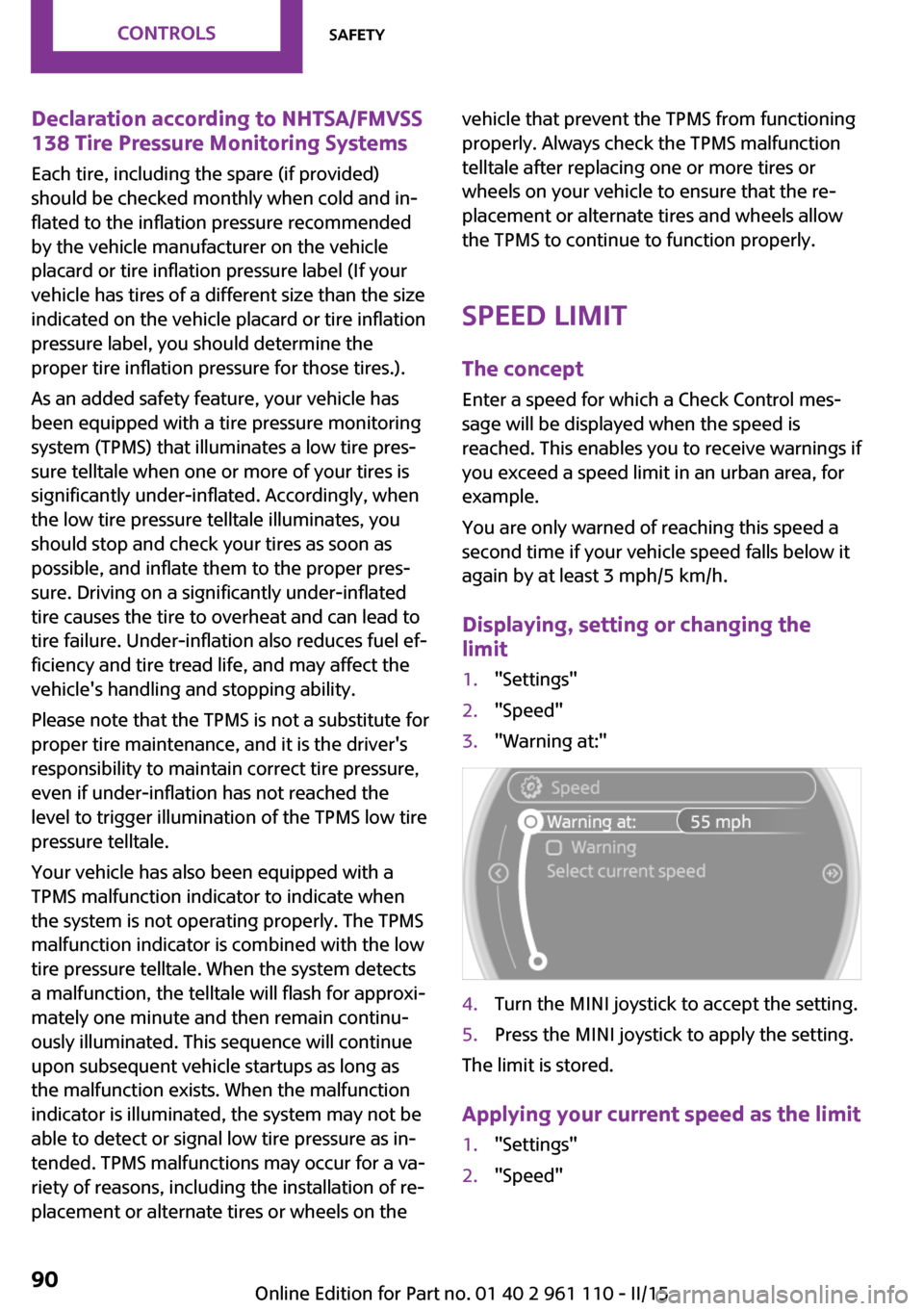
Displaying, setting or changing the
limit1."Settings"2."Speed"3."Warning at:"4.Turn the MINI joystick to accept the setting.5.Press the MINI joystick to apply the setting.
The limit is stored.
Applying your current speed as the limit
1."Settings"2."Speed"Seite 90CONTROLSSafety90
Online Edition for Part no. 01 40 2 961 110 - II/15
Page 95 of 283
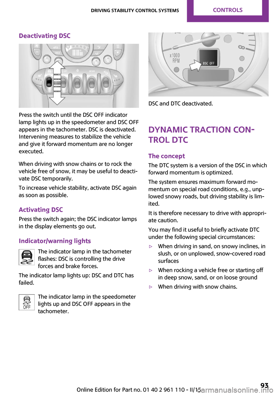
Deactivating DSC
Press the switch until the DSC OFF indicator
lamp lights up in the speedometer and DSC OFF
appears in the tachometer. DSC is deactivated.
Intervening measures to stabilize the vehicle
and give it forward momentum are no longer
executed.
When driving with snow chains or to rock the
vehicle free of snow, it may be useful to deacti‐
vate DSC temporarily.
To increase vehicle stability, activate DSC again
as soon as possible.
Activating DSC
Press the switch again; the DSC indicator lamps
in the display elements go out.
Indicator/warning lights The indicator lamp in the tachometer
flashes: DSC is controlling the drive
forces and brake forces.
The indicator lamp lights up: DSC and DTC has
failed.
The indicator lamp in the speedometer
lights up and DSC OFF appears in the
tachometer.
DSC and DTC deactivated.
Dynamic Traction Con‐
trol DTC
The concept
The DTC system is a version of the DSC in which
forward momentum is optimized.
The system ensures maximum forward mo‐
mentum on special road conditions, e.g., unp‐
lowed snowy roads, but driving stability is lim‐
ited.
It is therefore necessary to drive with appropri‐
ate caution.
You may find it useful to briefly activate DTC
under the following special circumstances:
▷When driving in sand, on snowy inclines, in
slush, or on unplowed, snow-covered road
surfaces▷When rocking a vehicle free or starting off
in deep snow, sand, or on loose ground▷When driving with snow chains.Seite 93Driving stability control systemsCONTROLS93
Online Edition for Part no. 01 40 2 961 110 - II/15