check engine MINI Countryman 2015 Owner's Manual (Mini Connected)
[x] Cancel search | Manufacturer: MINI, Model Year: 2015, Model line: Countryman, Model: MINI Countryman 2015Pages: 283, PDF Size: 6.76 MB
Page 17 of 283
Indicator/warning lights
The concept
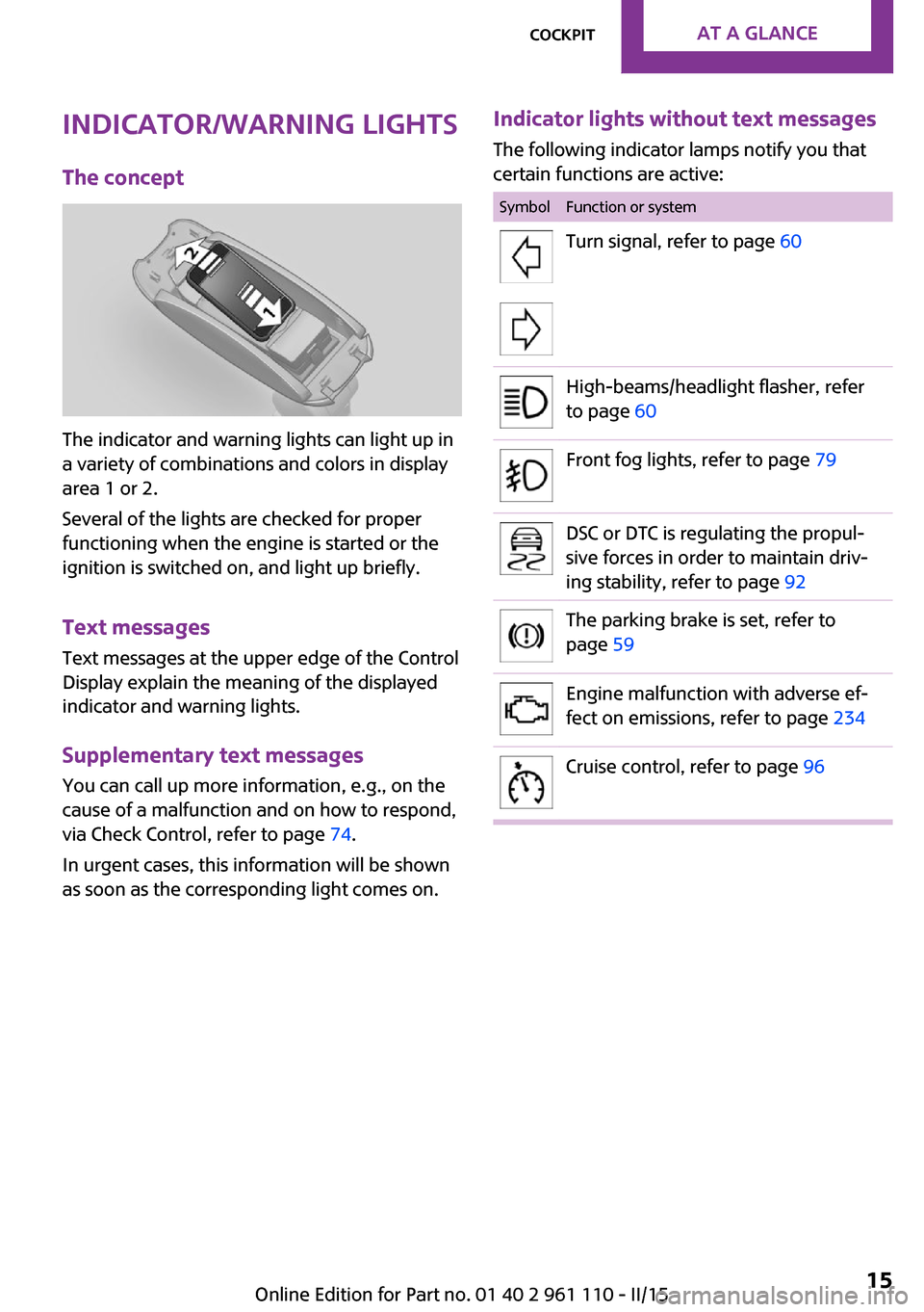
The indicator and warning lights can light up in
a variety of combinations and colors in display
area 1 or 2.
Several of the lights are checked for proper
functioning when the engine is started or the
ignition is switched on, and light up briefly.
Text messages
Text messages at the upper edge of the Control
Display explain the meaning of the displayed
indicator and warning lights.
Supplementary text messages
You can call up more information, e.g., on the
cause of a malfunction and on how to respond,
via Check Control, refer to page 74.
In urgent cases, this information will be shown
as soon as the corresponding light comes on.
Indicator lights without text messages
The following indicator lamps notify you that
certain functions are active:SymbolFunction or systemTurn signal, refer to page 60High-beams/headlight flasher, refer
to page 60Front fog lights, refer to page 79DSC or DTC is regulating the propul‐
sive forces in order to maintain driv‐
ing stability, refer to page 92The parking brake is set, refer to
page 59Engine malfunction with adverse ef‐
fect on emissions, refer to page 234Cruise control, refer to page 96Seite 15CockpitAT A GLANCE15
Online Edition for Part no. 01 40 2 961 110 - II/15
Page 39 of 283
MINI Paceman
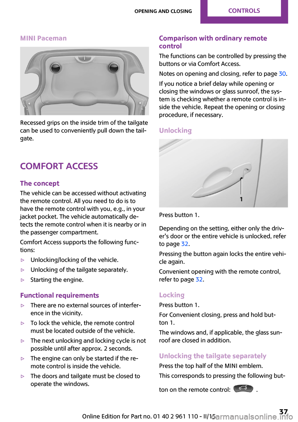
Recessed grips on the inside trim of the tailgate
can be used to conveniently pull down the tail‐
gate.
Comfort Access The concept
The vehicle can be accessed without activating
the remote control. All you need to do is to
have the remote control with you, e.g., in your
jacket pocket. The vehicle automatically de‐
tects the remote control when it is nearby or in
the passenger compartment.
Comfort Access supports the following func‐
tions:
▷Unlocking/locking of the vehicle.▷Unlocking of the tailgate separately.▷Starting the engine.
Functional requirements
▷There are no external sources of interfer‐
ence in the vicinity.▷To lock the vehicle, the remote control
must be located outside of the vehicle.▷The next unlocking and locking cycle is not
possible until after approx. 2 seconds.▷The engine can only be started if the re‐
mote control is inside the vehicle.▷The doors and tailgate must be closed to
operate the windows.Comparison with ordinary remote
control
The functions can be controlled by pressing the
buttons or via Comfort Access.
Notes on opening and closing, refer to page 30.
If you notice a brief delay while opening or
closing the windows or glass sunroof, the sys‐
tem is checking whether a remote control is in‐
side the vehicle. Repeat the opening or closing
procedure, if necessary.
Unlocking
Press button 1.
Depending on the setting, either only the driv‐
er's door or the entire vehicle is unlocked, refer
to page 32.
Pressing the button again locks the entire vehi‐
cle again.
Convenient opening with the remote control,
refer to page 32.
Locking
Press button 1.
For Convenient closing, press and hold but‐
ton 1.
The windows and, if applicable, the glass sun‐
roof are closed in addition.
Unlocking the tailgate separately
Press the top half of the MINI emblem.
This corresponds to pressing the following but‐
ton on the remote control:
.
Seite 37Opening and closingCONTROLS37
Online Edition for Part no. 01 40 2 961 110 - II/15
Page 40 of 283
If a remote control accidentally left in the cargo
area is detected in the locked vehicle after the
tailgate is closed, the tailgate opens again
slightly. The hazard warning system flashes and
an acoustic signal sounds.
Power windows and electrical glass
sunroof
When the engine is switched off, the windows
and the sunroof can be operated as long as
neither the doors nor the tailgate are opened.
When the door and tailgate are closed again
and the remote control is detected inside the
vehicle, the windows and the sunroof can be
operated again.
Insert the remote control into the ignition lock
to be able to operate the windows and the sun‐
roof while the engine is switched off and the
doors are open.
Switching on the radio ready state Press the Start/Stop button to switch on the
radio ready state, refer to page 57.
Do not depress the brake or the clutch; other‐
wise, the engine will start.
Starting the engine The engine can be started or the ignition can
be switched on, refer to page 57, when a re‐
mote control is inside the vehicle. It is not nec‐
essary to insert a remote control into the igni‐
tion lock.
Switching off the engine in cars with
Steptronic transmission
The engine can only be switched off with the
selector lever in position P, refer to page 64.
To switch off the engine with the selector lever
in position N, the remote control must be in‐
serted in the ignition lock.Before driving a vehicle with Steptronic
transmission into a car wash1.Insert the remote control into the ignition
switch.2.Depress the brake pedal.3.Move the selector lever to position N.4.Switch the engine off.
The vehicle can roll.
Malfunction The Comfort Access functions can be disturbed
by local radio waves, such as by a mobile
phone in the immediate vicinity of the remote
control or when a mobile phone is being
charged in the vehicle.
If this occurs, open or close the vehicle using
the buttons on the remote control or use the
integrated key in the door lock.
To start the engine afterward, insert the remote
control into the ignition switch.
Warning lights The warning light in the instrument
cluster lights up when you attempt to
start the engine: the engine cannot be
started.
The remote control is not in the vehicle or has a
malfunction. Take the remote control with you
inside the vehicle or have it checked. If neces‐
sary, insert another remote control into the ig‐
nition switch.
The warning lamp in the instrument
cluster lights up while the engine is run‐
ning: the remote control is no longer in‐
side the vehicle.
After switching off the engine, the engine can
only be started again within approx. 10 sec‐
onds if no door has been opened.
The indicator lamp lights up and a mes‐
sage appears on the Control Display: re‐
place the remote control battery.
Seite 38CONTROLSOpening and closing38
Online Edition for Part no. 01 40 2 961 110 - II/15
Page 70 of 283

Tachometer
It is imperative that you avoid engine speeds in
the red warning field. In this range, the fuel
supply is interrupted to protect the engine.
Coolant temperature A warning lamp will come on if the coolant, and
therefore the engine, becomes too hot. In addi‐
tion, a message will appear on the Control Dis‐
play.
Check the coolant level, refer to page 232.
Fuel gauge
The arrow next to the fuel pump symbol on the
fuel gauge indicates the side of the vehicle with
the fuel filler flap.
The vehicle inclination may cause the display to
vary.
Notes on refueling, refer to page 212.
Filling capacities, refer to page 261.
Range
After the reserve range is reached:▷The remaining LEDs change from orange to
red, arrow.▷A message is briefly displayed on the Con‐
trol Display.▷The remaining range is shown on the tach‐
ometer.▷When a dynamic driving style is used, such
as when corners are taken rapidly, engine
functions are not ensured.
The message appears continuously below a
range of approx. 30 miles/50 km.
Refuel promptly
At the latest, refuel at a range below
30 miles/50 km; otherwise, the engine function
is not ensured and damage may occur. ◀
Computer
Opening information in the tachometer
Press the button on the turn indicator lever.
Overview of the information
The following information is displayed consecu‐
tively by repeatedly pressing the button on the
turn indicator lever:
▷Range.▷Average fuel consumption.▷Current fuel consumption.▷Average speed.Seite 68CONTROLSDisplays68
Online Edition for Part no. 01 40 2 961 110 - II/15
Page 71 of 283
To set the corresponding units of measure, re‐
fer to page 71.
Information in detail
Range
Displays the estimated cruising range available
with the remaining fuel.
It is calculated based on your driving style over
the last 18 miles/30 km.
Average fuel consumption
This is calculated for the period during which
the engine is running.
With the trip computer, refer to page 69, the
average consumption can be displayed for an
additional distance.
To reset the average consumption: press the
button on the turn indicator lever for ap‐
prox. 2 seconds.
Current fuel consumption Displays the current fuel consumption. You can
check whether you are currently driving in an
efficient and environmentally-friendly manner.
Average speed Periods in which the vehicle was parked and
the engine was switched off manually are not
included in the average speed calculations.
With the trip computer, refer to page 69, the
average speed can be displayed for an addi‐
tional distance.
To reset the average speed: press the button
on the turn indicator lever for approx. 2 sec‐
onds.
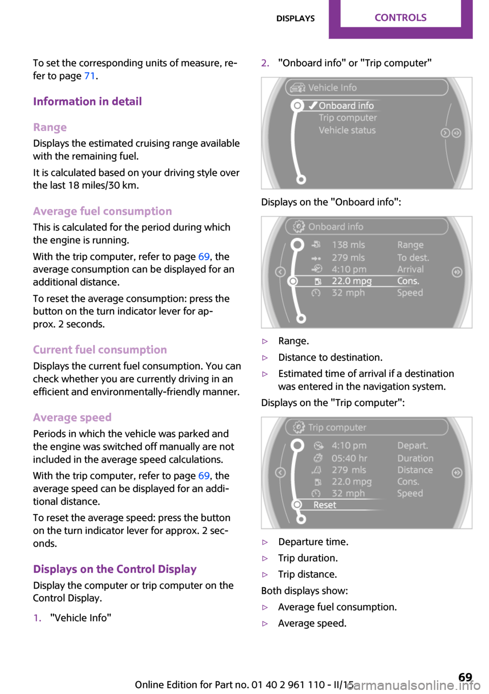
Displays on the Control Display Display the computer or trip computer on the
Control Display.1."Vehicle Info"2."Onboard info" or "Trip computer"
Displays on the "Onboard info":
▷Range.▷Distance to destination.▷Estimated time of arrival if a destination
was entered in the navigation system.
Displays on the "Trip computer":
▷Departure time.▷Trip duration.▷Trip distance.
Both displays show:
▷Average fuel consumption.▷Average speed.Seite 69DisplaysCONTROLS69
Online Edition for Part no. 01 40 2 961 110 - II/15
Page 76 of 283
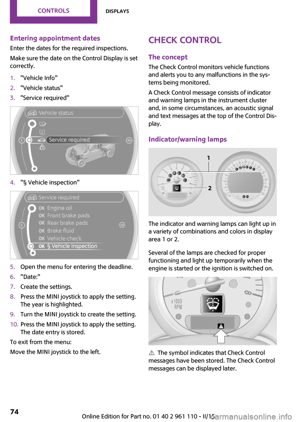
Entering appointment dates
Enter the dates for the required inspections.
Make sure the date on the Control Display is set
correctly.1."Vehicle Info"2."Vehicle status"3."Service required"4."§ Vehicle inspection"5.Open the menu for entering the deadline.6."Date:"7.Create the settings.8.Press the MINI joystick to apply the setting.
The year is highlighted.9.Turn the MINI joystick to create the setting.10.Press the MINI joystick to apply the setting.
The date entry is stored.
To exit from the menu:
Move the MINI joystick to the left.
Check Control
The concept
The Check Control monitors vehicle functions
and alerts you to any malfunctions in the sys‐
tems being monitored.
A Check Control message consists of indicator
and warning lamps in the instrument cluster
and, in some circumstances, an acoustic signal
and text messages at the top of the Control Dis‐
play.
Indicator/warning lamps
The indicator and warning lamps can light up in
a variety of combinations and colors in display
area 1 or 2.
Several of the lamps are checked for proper
functioning and light up temporarily when the
engine is started or the ignition is switched on.
The symbol indicates that Check Control
messages have been stored. The Check Control
messages can be displayed later.
Seite 74CONTROLSDisplays74
Online Edition for Part no. 01 40 2 961 110 - II/15
Page 87 of 283
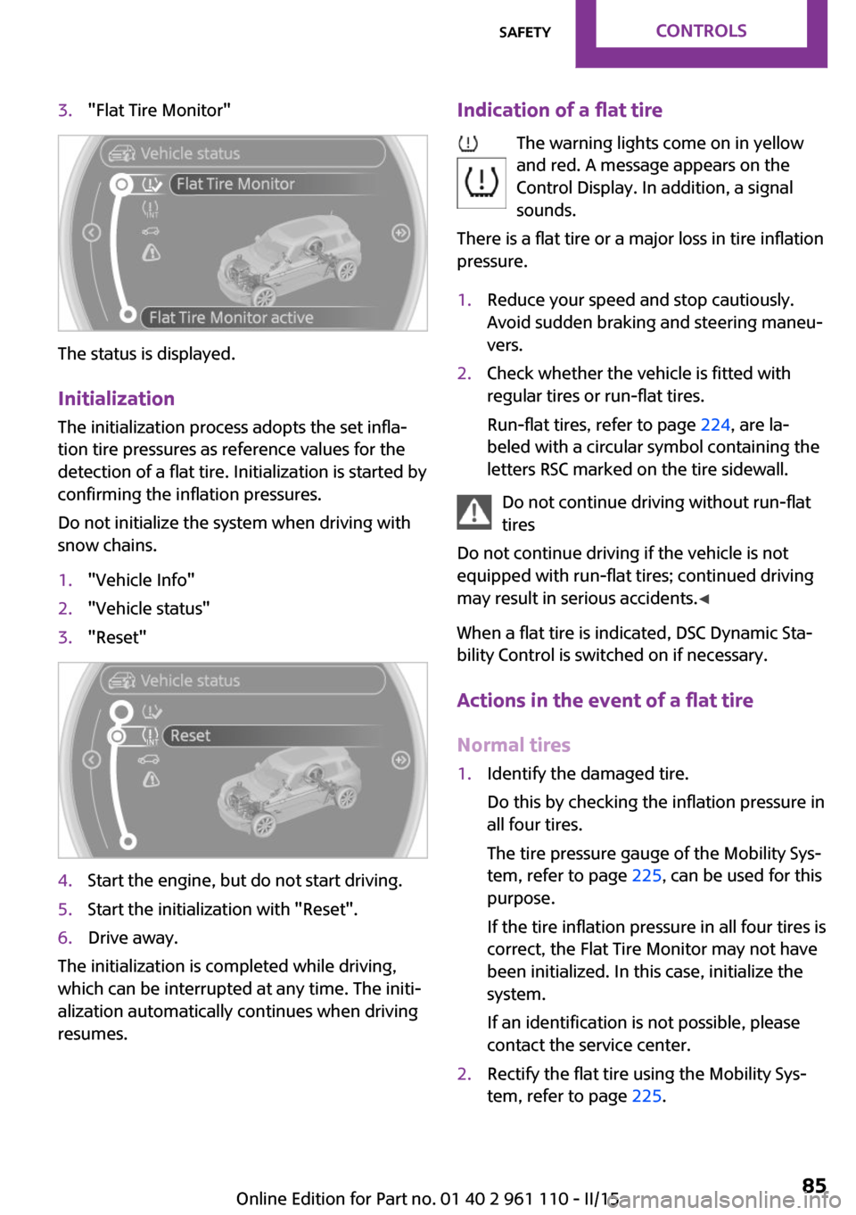
3."Flat Tire Monitor"
The status is displayed.
Initialization The initialization process adopts the set infla‐
tion tire pressures as reference values for the
detection of a flat tire. Initialization is started by
confirming the inflation pressures.
Do not initialize the system when driving with
snow chains.
1."Vehicle Info"2."Vehicle status"3."Reset"4.Start the engine, but do not start driving.5.Start the initialization with "Reset".6.Drive away.
The initialization is completed while driving,
which can be interrupted at any time. The initi‐
alization automatically continues when driving
resumes.
Indication of a flat tire
The warning lights come on in yellow
and red. A message appears on the
Control Display. In addition, a signal
sounds.
There is a flat tire or a major loss in tire inflation
pressure.1.Reduce your speed and stop cautiously.
Avoid sudden braking and steering maneu‐
vers.2.Check whether the vehicle is fitted with
regular tires or run-flat tires.
Run-flat tires, refer to page 224, are la‐
beled with a circular symbol containing the
letters RSC marked on the tire sidewall.
Do not continue driving without run-flat
tires
Do not continue driving if the vehicle is not
equipped with run-flat tires; continued driving
may result in serious accidents. ◀
When a flat tire is indicated, DSC Dynamic Sta‐
bility Control is switched on if necessary.
Actions in the event of a flat tire
Normal tires
1.Identify the damaged tire.
Do this by checking the inflation pressure in
all four tires.
The tire pressure gauge of the Mobility Sys‐
tem, refer to page 225, can be used for this
purpose.
If the tire inflation pressure in all four tires is
correct, the Flat Tire Monitor may not have
been initialized. In this case, initialize the
system.
If an identification is not possible, please
contact the service center.2.Rectify the flat tire using the Mobility Sys‐
tem, refer to page 225.Seite 85SafetyCONTROLS85
Online Edition for Part no. 01 40 2 961 110 - II/15
Page 89 of 283

Status displayThe current status of the Tire Pressure Monitor
TPM can be displayed on the Control Display,
e.g., whether or not the TPM is active.1."Vehicle Info"2."Vehicle status"3."Tire Pressure Monitor - TPM"
The status is displayed.
Status display The tire and system status is indicated on the
Control Display by the color of the tires and a
text.
All wheels are green The system is active and issues warnings based
on the tire inflation pressures stored during the
last reset.
One wheel is yellow A flat tire or major drop in inflation pressure in
the indicated tire.
All wheels are yellow A flat tire or major drop in inflation pressure in
several tires.
Wheels, gray
The system cannot detect a flat tire.
Reasons for this may be:
▷The system is being reset.▷Malfunction.Performing a reset
Perform a system reset after adjusting the tire
inflation pressure to a new value and after
changing a tire or wheel.1."Vehicle Info"2."Vehicle status"3."Reset"4.Start the engine - do not drive away.5.Start the initialization with "Reset".6.Drive away.
The wheels are shown in gray and the status is
displayed.
After a short trip at over 20 mph/30 km/h, the
set tire inflation pressures are adopted as tar‐
get values. The reset is completed automati‐
cally as you drive.
After a successful reset, the wheels appear in
green on the Control Display and "Status: TPM
active" is displayed.
The trip can be interrupted at any time. When
driving resumes, the reset is continued auto‐
matically.
Low tire pressure message The warning lights come on in yellow
and red. A Check Control message is
displayed. A message is displayed on
the onboard monitor. In addition, a sig‐
nal sounds.
▷There is a flat tire or substantial loss of infla‐
tion pressure on the indicated wheel.Seite 87SafetyCONTROLS87
Online Edition for Part no. 01 40 2 961 110 - II/15
Page 100 of 283
▷By the two corner sensors at ap‐
prox. 24 in/60 cm.▷By the rear middle sensors at approx.
5 ft/1.50 m.
Avoid driving quickly with PDC
PDC is a parking aid that can display ob‐
jects when the vehicle approaches them slowly,
as is the case during parking maneuvers. Avoid
driving toward an object quickly as the system
may then be too late in issuing a warning for
technical reasons. ◀
Automatic operation
The system is activated after approx. one sec‐ ond when reverse gear or selector lever posi‐
tion R is engaged while the engine is running or
the ignition is switched on. Await this short pe‐
riod before setting the vehicle into motion.
Signal tones
The closer the vehicle is to the object, the
shorter the intervals become. If the distance to
a detected object is less than approx.
12 in/30 cm, a continuous tone is sounded.
If the distance remains constant, for example
when driving parallel to a wall, the signal tone
is stopped after approx. 3 seconds.
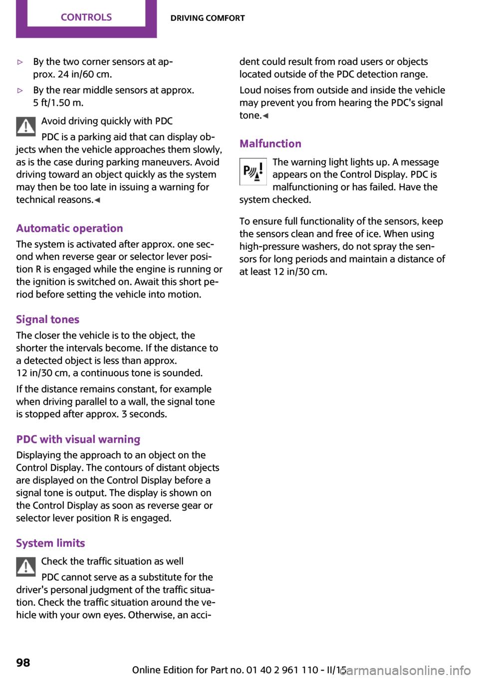
PDC with visual warning
Displaying the approach to an object on the
Control Display. The contours of distant objects
are displayed on the Control Display before a
signal tone is output. The display is shown on
the Control Display as soon as reverse gear or
selector lever position R is engaged.
System limits Check the traffic situation as well
PDC cannot serve as a substitute for the
driver's personal judgment of the traffic situa‐
tion. Check the traffic situation around the ve‐
hicle with your own eyes. Otherwise, an acci‐
dent could result from road users or objects
located outside of the PDC detection range.
Loud noises from outside and inside the vehicle
may prevent you from hearing the PDC's signal
tone. ◀
Malfunction The warning light lights up. A message
appears on the Control Display. PDC is
malfunctioning or has failed. Have the
system checked.
To ensure full functionality of the sensors, keep
the sensors clean and free of ice. When using
high-pressure washers, do not spray the sen‐
sors for long periods and maintain a distance of
at least 12 in/30 cm.Seite 98CONTROLSDriving comfort98
Online Edition for Part no. 01 40 2 961 110 - II/15
Page 125 of 283
Driving on poor roadsYour MINI with ALL4 all-wheel drive feels com‐
fortable on all streets and roads. It combines an
all-wheel drive system with the advantages of a
normal passenger car.
Do not drive on unpaved terrain
Do not drive on unpaved terrain, as oth‐
erwise the vehicle may be damaged. ◀
For your own safety and the safety of passen‐
gers and the vehicle, adhere to the following
points:▷Familiarize yourself with the vehicle before
driving; never take risks.▷Adjust speeds according to road conditions.
The steeper and rougher the road surface
is, the lower the speed should be.▷When driving on steep uphill and downhill
grades: the engine oil and coolant should
be filled nearly to the MAX mark.▷Watch for stones, holes, and other obsta‐
cles and drive around these where possible.▷On bumps and rough roads, avoid contact
between the vehicle body and the ground.
The maximum ground clearance is 6 in‐
ches/15 cm and may vary with the loaded
cargo.▷When driving through water, do not exceed
the maximum water height of 12 in‐
ches/30 cm and drive at walking speed.▷After driving through water, press on the
brake pedal several times at low speeds to
dry the brakes.▷Depending on the prevailing terrain, acti‐
vate Dynamic Traction Control DTC briefly,
refer to page 93.▷When the wheels spin, accelerate to enable
the driving stability control systems to dis‐
tribute the drive force to the individual
wheels.After driving on poor roads
Adhere to the following points to ensure vehi‐
cle safety:▷Remove excessive accumulations of dirt
and mud from the vehicle body.▷Clear mud, snow, ice, etc., from the wheels
and tires and check for damage.Seite 123Things to remember when drivingDRIVING TIPS123
Online Edition for Part no. 01 40 2 961 110 - II/15