fog light MINI Countryman 2015 Owner's Manual (Mini Connected)
[x] Cancel search | Manufacturer: MINI, Model Year: 2015, Model line: Countryman, Model: MINI Countryman 2015Pages: 283, PDF Size: 6.76 MB
Page 17 of 283
Indicator/warning lights
The concept
The indicator and warning lights can light up in
a variety of combinations and colors in display
area 1 or 2.
Several of the lights are checked for proper
functioning when the engine is started or the
ignition is switched on, and light up briefly.
Text messages
Text messages at the upper edge of the Control
Display explain the meaning of the displayed
indicator and warning lights.
Supplementary text messages
You can call up more information, e.g., on the
cause of a malfunction and on how to respond,
via Check Control, refer to page 74.
In urgent cases, this information will be shown
as soon as the corresponding light comes on.
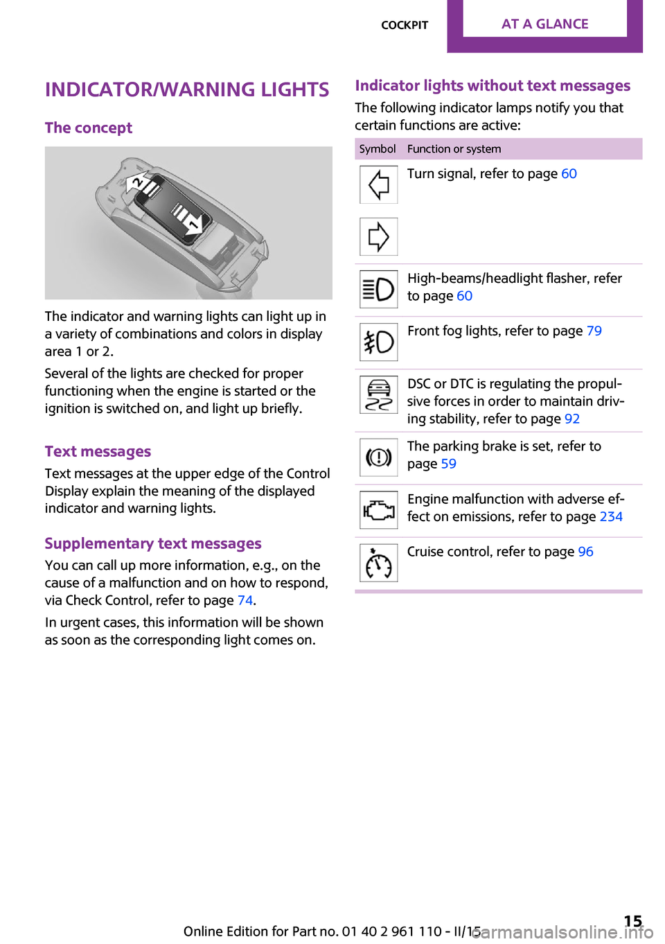
Indicator lights without text messages
The following indicator lamps notify you that
certain functions are active:SymbolFunction or systemTurn signal, refer to page 60High-beams/headlight flasher, refer
to page 60Front fog lights, refer to page 79DSC or DTC is regulating the propul‐
sive forces in order to maintain driv‐
ing stability, refer to page 92The parking brake is set, refer to
page 59Engine malfunction with adverse ef‐
fect on emissions, refer to page 234Cruise control, refer to page 96Seite 15CockpitAT A GLANCE15
Online Edition for Part no. 01 40 2 961 110 - II/15
Page 79 of 283
LampsVehicle equipmentThis chapter describes all series equipment as
well as country-specific and special equipment
offered for this model series. Therefore, it also
describes equipment that may not be found in
your vehicle, for instance due to the selected
special equipment or the country version. This
also applies to safety-related functions and sys‐
tems.
When using the features and systems described
here, adhere to local regulations.
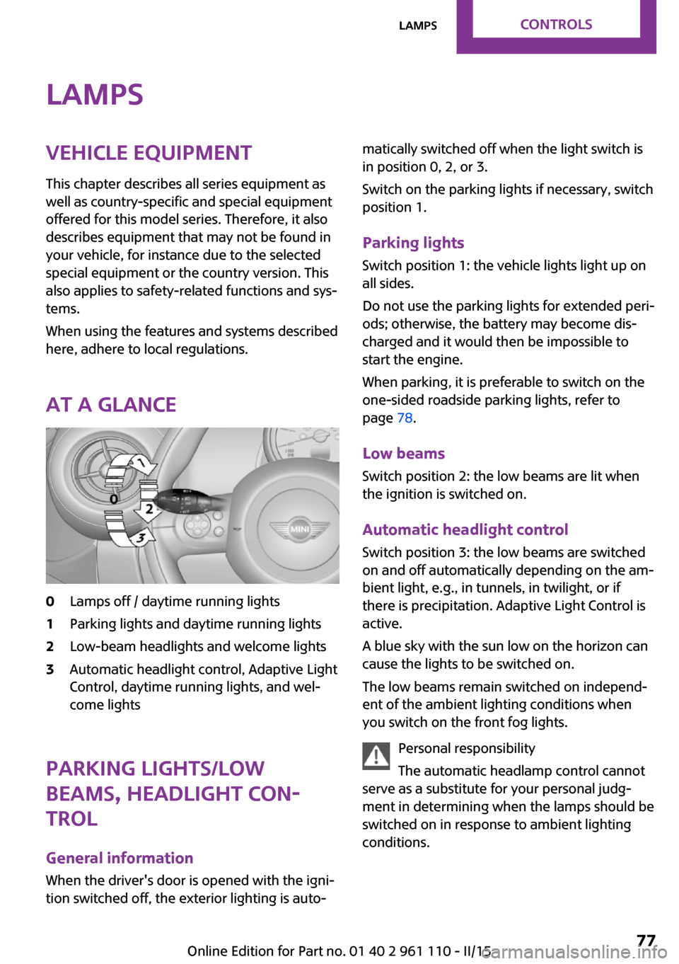
At a glance0Lamps off / daytime running lights1Parking lights and daytime running lights2Low-beam headlights and welcome lights3Automatic headlight control, Adaptive Light
Control, daytime running lights, and wel‐
come lights
Parking lights/low
beams, headlight con‐
trol
General information
When the driver's door is opened with the igni‐
tion switched off, the exterior lighting is auto‐
matically switched off when the light switch is
in position 0, 2, or 3.
Switch on the parking lights if necessary, switch
position 1.
Parking lights
Switch position 1: the vehicle lights light up on
all sides.
Do not use the parking lights for extended peri‐
ods; otherwise, the battery may become dis‐
charged and it would then be impossible to
start the engine.
When parking, it is preferable to switch on the
one-sided roadside parking lights, refer to
page 78.
Low beams Switch position 2: the low beams are lit when
the ignition is switched on.
Automatic headlight control
Switch position 3: the low beams are switched
on and off automatically depending on the am‐
bient light, e.g., in tunnels, in twilight, or if
there is precipitation. Adaptive Light Control is
active.
A blue sky with the sun low on the horizon can
cause the lights to be switched on.
The low beams remain switched on independ‐
ent of the ambient lighting conditions when
you switch on the front fog lights.
Personal responsibility
The automatic headlamp control cannot
serve as a substitute for your personal judg‐
ment in determining when the lamps should be
switched on in response to ambient lighting
conditions.Seite 77LampsCONTROLS77
Online Edition for Part no. 01 40 2 961 110 - II/15
Page 80 of 283
For example, the sensors are unable to detect
fog or hazy weather. To avoid safety risks, you
should always switch on the lamps manually
under these conditions. ◀
The exterior lighting goes out automatically af‐
ter the vehicle is switched off.
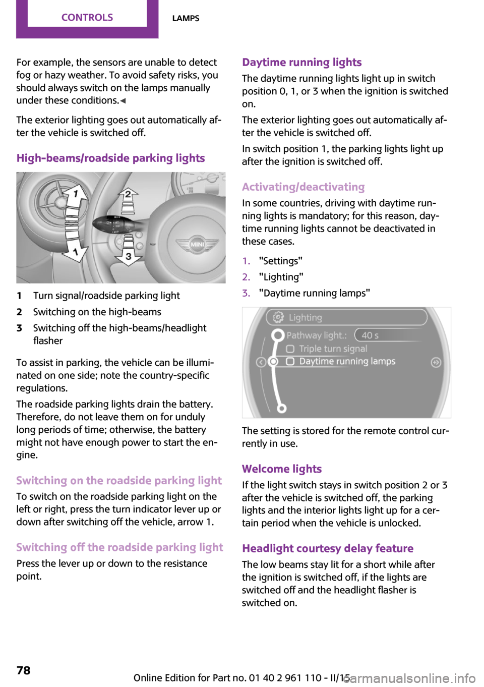
High-beams/roadside parking lights1Turn signal/roadside parking light2Switching on the high-beams3Switching off the high-beams/headlight
flasher
To assist in parking, the vehicle can be illumi‐
nated on one side; note the country-specific
regulations.
The roadside parking lights drain the battery.
Therefore, do not leave them on for unduly
long periods of time; otherwise, the battery
might not have enough power to start the en‐
gine.
Switching on the roadside parking light
To switch on the roadside parking light on the
left or right, press the turn indicator lever up or
down after switching off the vehicle, arrow 1.
Switching off the roadside parking light
Press the lever up or down to the resistance
point.
Daytime running lights
The daytime running lights light up in switch
position 0, 1, or 3 when the ignition is switched
on.
The exterior lighting goes out automatically af‐
ter the vehicle is switched off.
In switch position 1, the parking lights light up
after the ignition is switched off.
Activating/deactivating
In some countries, driving with daytime run‐
ning lights is mandatory; for this reason, day‐
time running lights cannot be deactivated in
these cases.1."Settings"2."Lighting"3."Daytime running lamps"
The setting is stored for the remote control cur‐
rently in use.
Welcome lights If the light switch stays in switch position 2 or 3
after the vehicle is switched off, the parking
lights and the interior lights light up for a cer‐
tain period when the vehicle is unlocked.
Headlight courtesy delay feature The low beams stay lit for a short while after
the ignition is switched off, if the lights are
switched off and the headlight flasher is
switched on.
Seite 78CONTROLSLamps78
Online Edition for Part no. 01 40 2 961 110 - II/15
Page 81 of 283
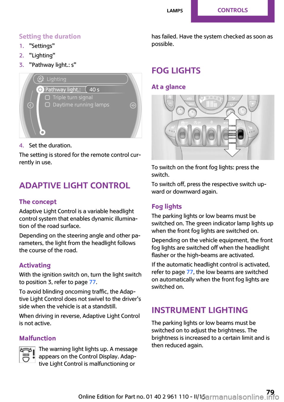
Setting the duration1."Settings"2."Lighting"3."Pathway light.: s"4.Set the duration.
The setting is stored for the remote control cur‐
rently in use.
Adaptive Light Control
The concept
Adaptive Light Control is a variable headlight
control system that enables dynamic illumina‐
tion of the road surface.
Depending on the steering angle and other pa‐
rameters, the light from the headlight follows
the course of the road.
Activating
With the ignition switch on, turn the light switch
to position 3, refer to page 77.
To avoid blinding oncoming traffic, the Adap‐
tive Light Control does not swivel to the driver's
side when the vehicle is at a standstill.
When driving in reverse, Adaptive Light Control
is not active.
Malfunction The warning light lights up. A message
appears on the Control Display. Adap‐
tive Light Control is malfunctioning or
has failed. Have the system checked as soon as
possible.
Fog lights At a glance
To switch on the front fog lights: press the
switch.
To switch off, press the respective switch up‐
ward or downward again.
Fog lights The parking lights or low beams must be
switched on. The green indicator lamp lights up
when the front fog lights are switched on.
Depending on the vehicle equipment, the front
fog lights are switched off when the headlight
flasher or the high-beams are activated.
If the automatic headlight control is activated,
refer to page 77, the low beams are switched
on automatically when the front fog lights are
switched on.
Instrument lighting The parking lights or low beams must be
switched on to adjust the brightness. The
brightness is increased to a certain limit and is then reduced again.
Seite 79LampsCONTROLS79
Online Edition for Part no. 01 40 2 961 110 - II/15
Page 98 of 283
Driving comfortVehicle equipment
This chapter describes all series equipment as
well as country-specific and special equipment
offered for this model series. Therefore, it also
describes equipment that may not be found in
your vehicle, for instance due to the selected
special equipment or the country version. This
also applies to safety-related functions and sys‐
tems.
When using the features and systems described
here, adhere to local regulations.
Cruise control
The concept
The system is functional at speeds beginning at
approx. 20 mph/30 km/h.
The vehicle stores and maintains the speed
specified using the controls on the steering
wheel.
Do not use cruise control
Do not use the system if unfavorable con‐
ditions make it impossible to drive at a constant
speed, for instance:▷On curvy roads.▷In heavy traffic.▷On slippery roads, in fog, snow or rain, or
on a loose road surface.
Otherwise, you could lose control of the vehicle
and cause an accident. ◀
Controls
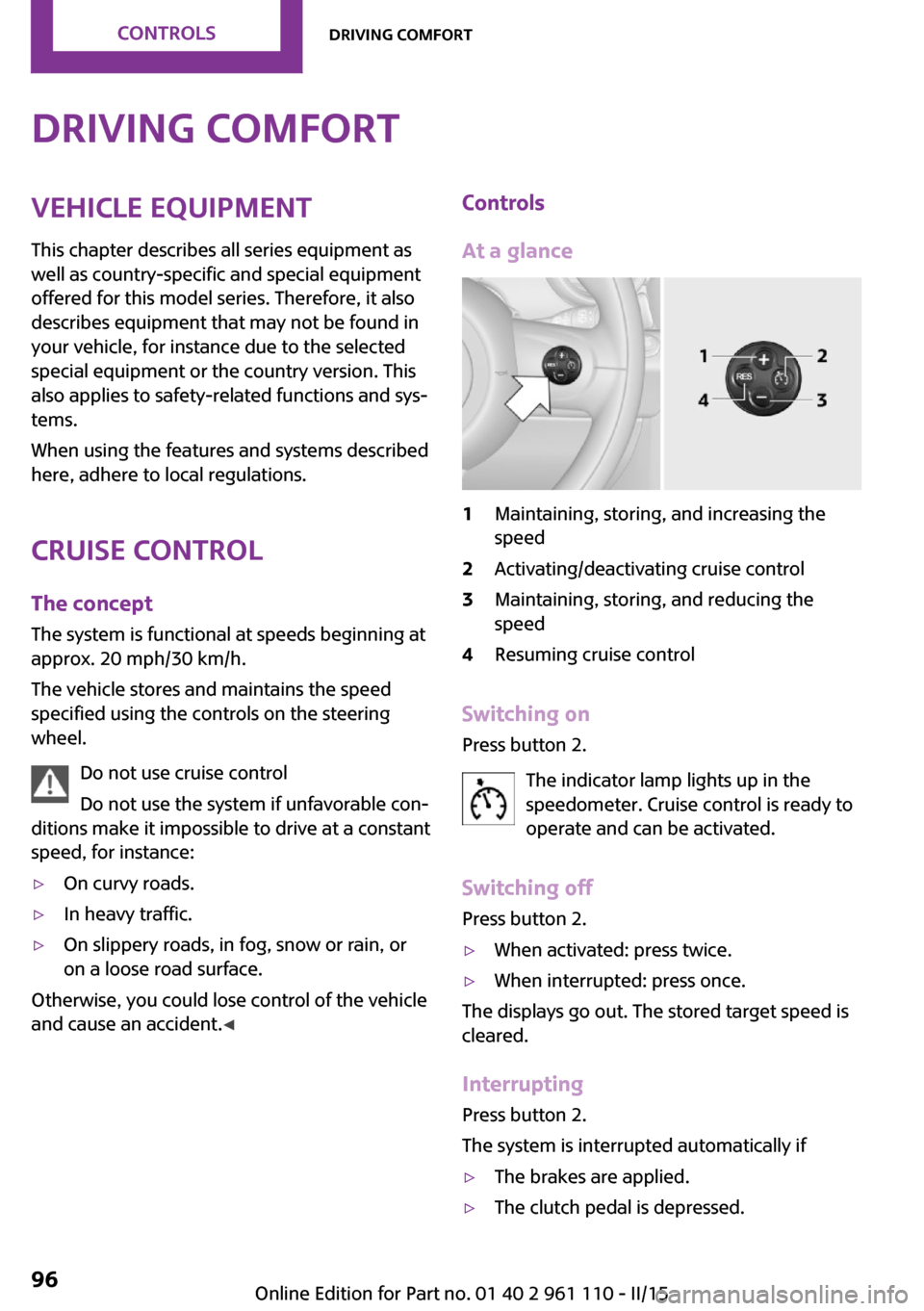
At a glance1Maintaining, storing, and increasing the
speed2Activating/deactivating cruise control3Maintaining, storing, and reducing the
speed4Resuming cruise control
Switching on
Press button 2.
The indicator lamp lights up in thespeedometer. Cruise control is ready to
operate and can be activated.
Switching off Press button 2.
▷When activated: press twice.▷When interrupted: press once.
The displays go out. The stored target speed is
cleared.
Interrupting Press button 2.
The system is interrupted automatically if
▷The brakes are applied.▷The clutch pedal is depressed.Seite 96CONTROLSDriving comfort96
Online Edition for Part no. 01 40 2 961 110 - II/15
Page 238 of 283

Lamp and bulb replace‐
ment
Notes
Lamps and bulbs Lamps and bulbs make an essential contribu‐
tion to vehicle safety. Therefore, exercise cau‐
tion when handling lights and bulbs.
The manufacturer of the vehicle recommends
that you entrust corresponding procedures to
the service center if you are unfamiliar with
them or they are not described here.
You can obtain a selection of replacement
bulbs at the service center.
Danger of burns
Only change bulbs when they are cool;
otherwise, there is the danger of getting
burned. ◀
Working on the lighting system
When working on the lighting system,
you should always switch off the lights affected
to prevent short circuits.
To avoid possible injury or equipment damage
when replacing bulbs, observe any instructions
provided by the bulb manufacturer. ◀
Do not touch the bulbs
Do not touch the glass of new bulbs with
your bare hands, as even minute amounts of
contamination will burn into the bulb's surface
and reduce its service life.
Use a clean tissue, cloth or something similar,
or hold the bulb by its base. ◀
Caring for the headlights, refer to page 251.
For bulb replacement that is not described
here, please contact the service center or a
workshop that works according to the repair
procedures of the manufacturer with corre‐
spondingly trained personnel.For checking and adjusting headlight aim,
please contact your MINI dealer.
Light-emitting diodes LEDs In some equipment, the light source is provided
by light-emitting diodes behind a cover.
These light-emitting diodes, which operate us‐
ing a concept similar to that applied in conven‐
tional lasers, are designated as Class 1 light-
emitting diodes.
Do not remove the covers
Do not remove the covers, and never
stare into the unfiltered light for several hours;
otherwise, irritation of the retina could result. ◀
Headlight glass Condensation can form on the inside of the
headlights in cool or humid weather. When the
light is switched on, the condensation evapo‐
rates after a short time. The headlights do not
need to be changed.
If the condensation in the headlights does not
evaporate after trips with the lights switched
on, and the amount of moisture in the head‐
lights increases, for example if water droplets
form, have them checked by your service cen‐
ter.
Bi-xenon headlights
These bulbs have a very long life and the likeli‐
hood of failure is very low, provided that they
are not switched on and off excessively. If a
bulb should nevertheless fail, you can continue
driving cautiously with the front fog lights, pro‐
vided this is permitted by local laws.
Do not perform work/bulb replacement
on xenon headlamps
Have any work on the xenon lighting system,
including bulb replacement, performed only by
a service center.
Due to the high voltage present in the system,
there is the danger of fatal injuries if work is
carried out improperly. ◀Seite 236MOBILITYReplacing components236
Online Edition for Part no. 01 40 2 961 110 - II/15
Page 239 of 283
Front lights, bulb replacement
At a glance
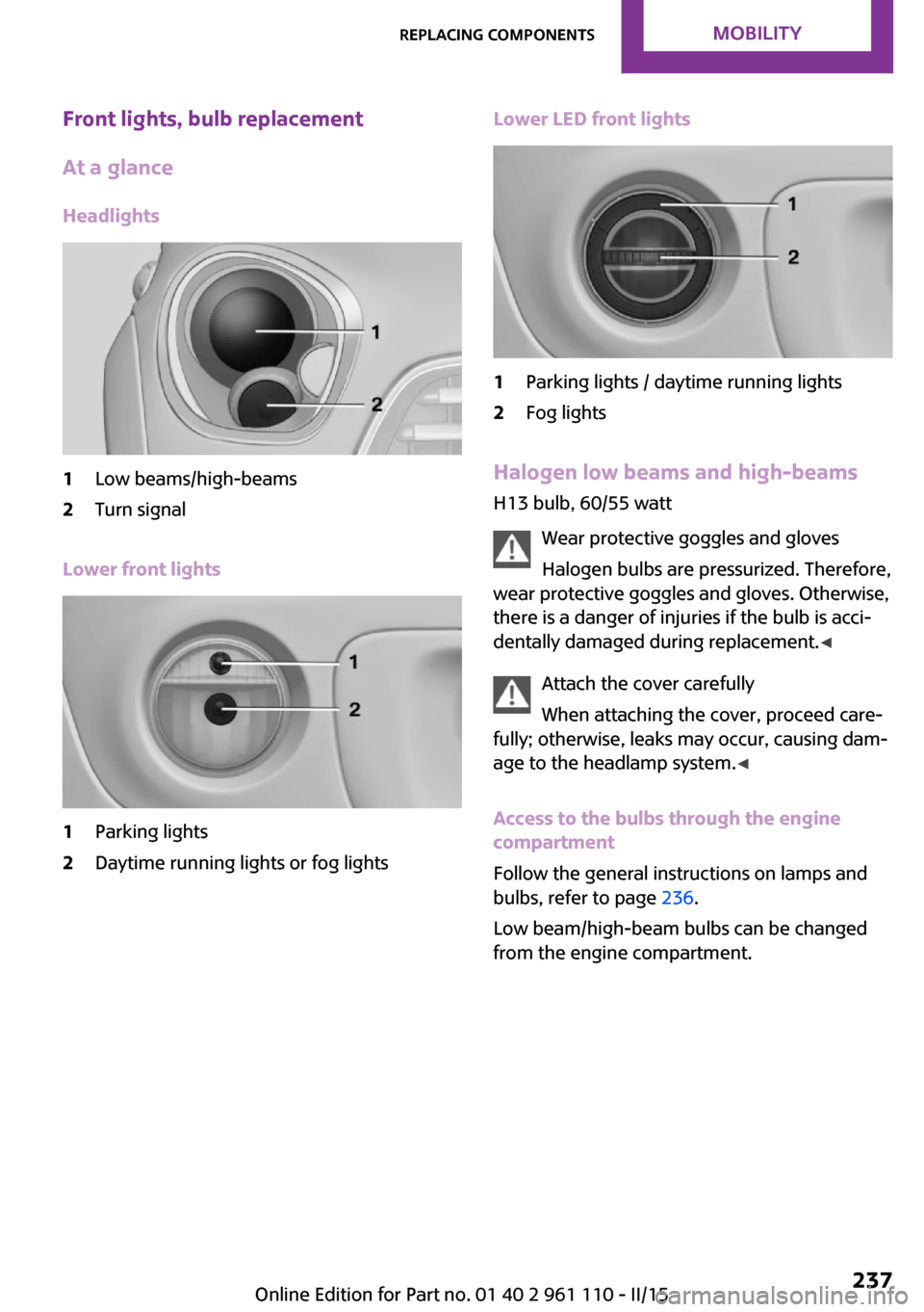
Headlights1Low beams/high-beams2Turn signal
Lower front lights
1Parking lights2Daytime running lights or fog lightsLower LED front lights1Parking lights / daytime running lights2Fog lights
Halogen low beams and high-beams
H13 bulb, 60/55 watt
Wear protective goggles and glovesHalogen bulbs are pressurized. Therefore,
wear protective goggles and gloves. Otherwise,
there is a danger of injuries if the bulb is acci‐
dentally damaged during replacement. ◀
Attach the cover carefully
When attaching the cover, proceed care‐
fully; otherwise, leaks may occur, causing dam‐
age to the headlamp system. ◀
Access to the bulbs through the engine
compartment
Follow the general instructions on lamps and
bulbs, refer to page 236.
Low beam/high-beam bulbs can be changed
from the engine compartment.
Seite 237Replacing componentsMOBILITY237
Online Edition for Part no. 01 40 2 961 110 - II/15
Page 240 of 283

To remove the cover:
1.Press the tab.2.Fold away the cover and take it out of the
holder.
Proceed in reverse order to attach the cover.
Attach the cover carefully
When attaching the cover, proceed care‐
fully; otherwise, leaks may occur, causing dam‐
age to the headlamp system. ◀
Replacing the bulb
1.Turn the bulb counterclockwise, arrow 1,
and remove it, arrow 2.2.Press the release, arrow 1, and pull off the
connector, arrow 2.3.Insert the new bulb and attach the cover in
reverse order.
LED parking lights/LED fog lights/LED
daytime running lights
Follow the general instructions on lamps and
bulbs, refer to page 236.
Lights are implemented using LED technology.
Contact your service center in the event of a
malfunction.
Turn signals/parking lights/roadside
parking lights/fog lights/and daytime
running lights
Access to the bulbs via the wheel housing
Follow the general instructions on lamps and
bulbs, refer to page 236.
1Turn signal2Parking lights/roadside parking lights/fog
lights/and daytime running lights
Replacing the turn signal bulb
21-watt bulb, P 21 W, or PY 21 W
1.Turn the wheel.2.Remove cover 1.
To do this, turn the cover counterclockwise.Seite 238MOBILITYReplacing components238
Online Edition for Part no. 01 40 2 961 110 - II/15
Page 241 of 283

3.Remove the inside cover. To do this, turn
the cover counterclockwise.4.Turn the bulb counterclockwise and re‐
move it.5.Insert the new bulb and attach the covers
in reverse order.
Replacing the parking light bulb and
roadside parking light bulb
5-watt bulb, W 5 W
1.Turn the wheel.2.Remove cover 2.
To do this, turn the cover counterclockwise.3.Turn the upper bulb counterclockwise and
remove it.4.Insert the new bulb and attach the cover in
reverse order.
Replacing the front fog light bulb
H8 bulb, 35 watt
1.Turn the wheel.2.Remove cover 2.
To do this, turn the cover counterclockwise.3.Pull off the plug-in cable connector.4.Turn the lower bulb counterclockwise and
remove it.5.Insert the new bulb and attach the cover in
reverse order.
Replacing the daytime running light bulb
Bulb PSX24W
1.Turn the wheel.2.Remove cover 2.
To do this, turn the cover counterclockwise.3.Pull off the plug-in cable connector.Seite 239Replacing componentsMOBILITY239
Online Edition for Part no. 01 40 2 961 110 - II/15
Page 272 of 283
Combination switch, refer toTurn signal/high-beams/
headlight flasher 60
Combination switch, refer to Washer/wiper system 60
Comfort Access 37
Comfort Access, in the car wash 38
Comfort Access, replacing the battery 39
Comfort area, refer to Around the center console 16
Compartment for remote con‐ trol, refer to Ignition lock 57
Compass, digital 107
Computer 68
Computer, displaying informa‐ tion 68
Condition Based Service CBS 233
Confirmation signals for vehi‐ cle locking/unlocking 33
Connecting, mobile phone, re‐ fer to Mobile phone, pairing,
hands-free system 179
Connecting, mobile phone, re‐ fer to Pairing the mobile
phone 189
Consumption, refer to Aver‐ age fuel consumption 69
Contacts for hands-free sys‐ tem 185
Contacts, office 200
Control Display 18
Control Display, care 253
Control Display, settings 72
Controls and displays 12
Control systems, driving stabil‐ ity 92
Convenient operation, win‐ dow 32
Coolant temperature 68
Cooling function, switching on and off 103
Cooling, maximum 102 Cornering Brake Control,
CBC 92
Corrosion on brake discs 122
Cradle for telephone or mobile phone, refer to Snap-in
adapter 198
Cruise control 96
Cupholders 109
Current fuel consumption 69
Current location, storing 136
Curve lights, refer to Adaptive Light Control 79
D Dashboard lighting, refer to Instrument lighting 79
Dashboard, refer to Cock‐ pit 12
Dashboard, refer to Dis‐ plays 14
Date, date format 72
Date, setting 72
Daytime running lights 78
Decorative trim, care 253
Defogging windows 100
Defroster, rear window, auto‐ matic climate control 103
Defroster, rear window, with air conditioner 100
Defrosting windows 100
Defrost setting, refer to De‐ frosting windows 100
Destination entry via the ad‐ dress book 136
Destination guidance with in‐ termediate destinations 141
Destination input, naviga‐ tion 134
Digital compass 107
Digital radio 158
Dip stick, engine oil 230
Directional indicators, refer to Turn signals 60
Display lighting, refer to In‐ strument lighting 79 Displays 14
Displays and controls 12
Displays, care 253
Displays, cleaning 253
Displays, refer to Instrument cluster 14
Disposal, remote control bat‐ tery 39
Distance warning, refer to Park Distance Control
PDC 97
Door key, refer to Remote control with integrated
key 30
Door lock 34
Door lock, confirmation sig‐ nals 33
Doors, manual operation 34
Doors, unlocking and locking, confirmation signals 33
Doors, unlocking and locking from the inside 34
Doors, unlocking and locking, from the outside 32
DOT Quality Grades 220
Drive-off assistant, refer to Hill drive-off assistant 94
Driving notes, breaking in 120
Driving off on hills, refer to Hill drive-off assistant 94
Driving on poor roads 123
Driving stability control sys‐ tems 92
Driving tips, refer to Driving notes 120
Dry air, refer to Cooling func‐ tion 103
DSC Dynamic Stability Con‐ trol 92
DTC Dynamic Traction Con‐ trol 93
DTMF suffix dialing, hands- free system 181 Seite 270REFERENCEEverything from A to Z270
Online Edition for Part no. 01 40 2 961 110 - II/15