stop start MINI Countryman 2015 Owner's Manual (Mini Connected)
[x] Cancel search | Manufacturer: MINI, Model Year: 2015, Model line: Countryman, Model: MINI Countryman 2015Pages: 283, PDF Size: 6.76 MB
Page 15 of 283
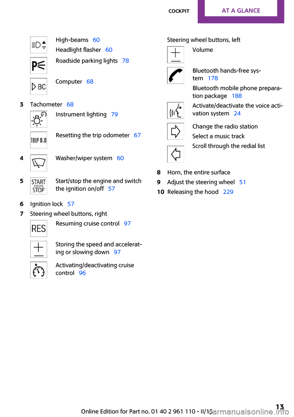
High-beams 60
Headlight flasher 60Roadside parking lights 78Computer 683Tachometer 68Instrument lighting 79Resetting the trip odometer 674Washer/wiper system 605Start/stop the engine and switch
the ignition on/off 576Ignition lock 577Steering wheel buttons, rightResuming cruise control 97Storing the speed and accelerat‐
ing or slowing down 97Activating/deactivating cruise
control 96Steering wheel buttons, leftVolumeBluetooth hands-free sys‐
tem 178
Bluetooth mobile phone prepara‐
tion package 188Activate/deactivate the voice acti‐
vation system 24Change the radio station
Select a music track
Scroll through the redial list8Horn, the entire surface9Adjust the steering wheel 5110Releasing the hood 229Seite 13CockpitAT A GLANCE13
Online Edition for Part no. 01 40 2 961 110 - II/15
Page 40 of 283
If a remote control accidentally left in the cargo
area is detected in the locked vehicle after the
tailgate is closed, the tailgate opens again
slightly. The hazard warning system flashes and
an acoustic signal sounds.
Power windows and electrical glass
sunroof
When the engine is switched off, the windows
and the sunroof can be operated as long as
neither the doors nor the tailgate are opened.
When the door and tailgate are closed again
and the remote control is detected inside the
vehicle, the windows and the sunroof can be
operated again.
Insert the remote control into the ignition lock
to be able to operate the windows and the sun‐
roof while the engine is switched off and the
doors are open.
Switching on the radio ready state Press the Start/Stop button to switch on the
radio ready state, refer to page 57.
Do not depress the brake or the clutch; other‐
wise, the engine will start.
Starting the engine The engine can be started or the ignition can
be switched on, refer to page 57, when a re‐
mote control is inside the vehicle. It is not nec‐
essary to insert a remote control into the igni‐
tion lock.
Switching off the engine in cars with
Steptronic transmission
The engine can only be switched off with the
selector lever in position P, refer to page 64.
To switch off the engine with the selector lever
in position N, the remote control must be in‐
serted in the ignition lock.Before driving a vehicle with Steptronic
transmission into a car wash1.Insert the remote control into the ignition
switch.2.Depress the brake pedal.3.Move the selector lever to position N.4.Switch the engine off.
The vehicle can roll.
Malfunction The Comfort Access functions can be disturbed
by local radio waves, such as by a mobile
phone in the immediate vicinity of the remote
control or when a mobile phone is being
charged in the vehicle.
If this occurs, open or close the vehicle using
the buttons on the remote control or use the
integrated key in the door lock.
To start the engine afterward, insert the remote
control into the ignition switch.
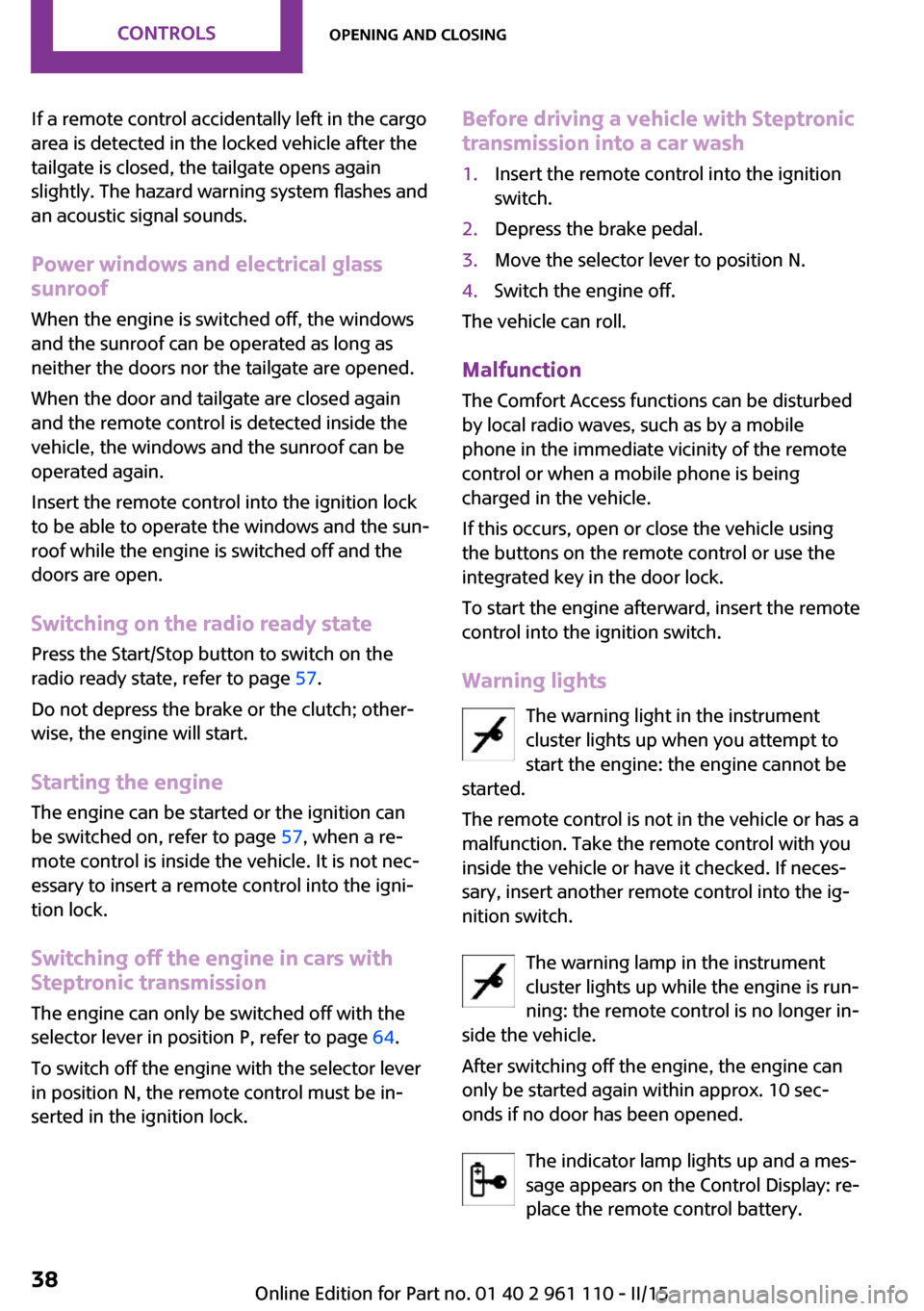
Warning lights The warning light in the instrument
cluster lights up when you attempt to
start the engine: the engine cannot be
started.
The remote control is not in the vehicle or has a
malfunction. Take the remote control with you
inside the vehicle or have it checked. If neces‐
sary, insert another remote control into the ig‐
nition switch.
The warning lamp in the instrument
cluster lights up while the engine is run‐
ning: the remote control is no longer in‐
side the vehicle.
After switching off the engine, the engine can
only be started again within approx. 10 sec‐
onds if no door has been opened.
The indicator lamp lights up and a mes‐
sage appears on the Control Display: re‐
place the remote control battery.
Seite 38CONTROLSOpening and closing38
Online Edition for Part no. 01 40 2 961 110 - II/15
Page 59 of 283
DrivingVehicle equipmentThis chapter describes all series equipment as
well as country-specific and special equipment
offered for this model series. Therefore, it also
describes equipment that may not be found in
your vehicle, for instance due to the selected
special equipment or the country version. This
also applies to safety-related functions and sys‐
tems.
When using the features and systems described
here, adhere to local regulations.
Ignition lock
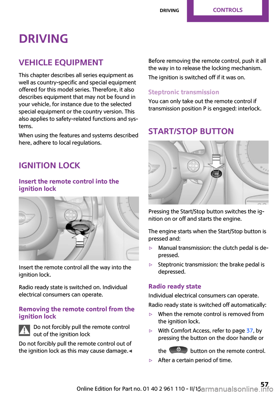
Insert the remote control into the
ignition lock
Insert the remote control all the way into the
ignition lock.
Radio ready state is switched on. Individual
electrical consumers can operate.
Removing the remote control from the
ignition lock
Do not forcibly pull the remote control
out of the ignition lock
Do not forcibly pull the remote control out of
the ignition lock as this may cause damage. ◀
Before removing the remote control, push it all
the way in to release the locking mechanism.
The ignition is switched off if it was on.
Steptronic transmission You can only take out the remote control if
transmission position P is engaged: interlock.
Start/Stop button
Pressing the Start/Stop button switches the ig‐
nition on or off and starts the engine.
The engine starts when the Start/Stop button is
pressed and:
▷Manual transmission: the clutch pedal is de‐
pressed.▷Steptronic transmission: the brake pedal is
depressed.
Radio ready state
Individual electrical consumers can operate.
Radio ready state is switched off automatically:
▷When the remote control is removed from
the ignition lock.▷With Comfort Access, refer to page 37, by
pressing the button on the door handle or
the
button on the remote control.
▷After a certain period of time.Seite 57DrivingCONTROLS57
Online Edition for Part no. 01 40 2 961 110 - II/15
Page 60 of 283
Ignition onAll electrical consumers can operate. Most indi‐
cator and warning lights light up for different
lengths of time.
To save battery power when the engine is off,
switch off the ignition and any unnecessary electronic systems/power consumers.
Radio ready state and ignition off All indicator and warning lights in the displays
go out.
The ignition switches off automatically when
the driver's door is opened. Pressing the Start/
Stop button again switches the ignition back
on.
For example, the ignition is not switched off in
the following situations:▷Depress the clutch or brake pedal.▷The low beams are switched on.
Starting the engine
General information Enclosed areas
Do not let the engine run in enclosed
areas; otherwise, breathing of exhaust fumes
may lead to loss of consciousness and death.
The exhaust gases contain carbon monoxide,
an odorless and colorless but highly toxic gas. ◀
Unattended vehicle
Do not leave the car unattended with the
engine running; otherwise, it presents a poten‐
tial source of danger.
Before leaving the car with the engine running,
shift to neutral or engage transmission posi‐
tion P and set the parking brake firmly; other‐ wise, the vehicle may begin to roll. ◀
Frequent starting in quick succession
Avoid repeated futile attempts at starting
the car and avoid starting the car frequently in
quick succession. Otherwise, the fuel is not
burned or is inadequately burned, and there is
the danger of overheating and damaging the
catalytic converter. ◀
Do not wait for the engine to warm-up while
the vehicle remains stationary; start driving
right away, but at moderate engine speeds.
Do not depress the accelerator when starting
the engine.
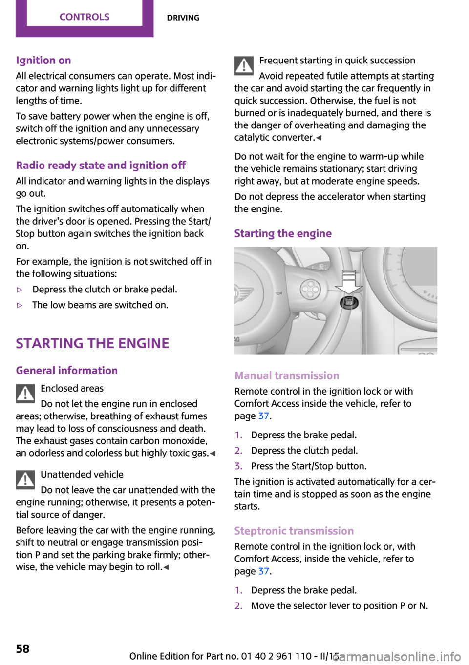
Starting the engine
Manual transmission
Remote control in the ignition lock or with
Comfort Access inside the vehicle, refer to
page 37.
1.Depress the brake pedal.2.Depress the clutch pedal.3.Press the Start/Stop button.
The ignition is activated automatically for a cer‐
tain time and is stopped as soon as the engine
starts.
Steptronic transmission
Remote control in the ignition lock or, with
Comfort Access, inside the vehicle, refer to
page 37.
1.Depress the brake pedal.2.Move the selector lever to position P or N.Seite 58CONTROLSDriving58
Online Edition for Part no. 01 40 2 961 110 - II/15
Page 61 of 283
3.Press the Start/Stop button.
The ignition is activated automatically for a cer‐
tain time and is stopped as soon as the engine
starts.
Engine stop
General information Take the remote control with you
Take the remote control with you when
leaving the vehicle so that children, for exam‐
ple, cannot operate the windows and injure
themselves. ◀
Set the parking brake and further secure
the vehicle as required
Set the parking brake firmly when parking; oth‐
erwise, the vehicle may roll. On steep upward
and downward inclines, further secure the ve‐
hicle, for example, by turning the steering
wheel in the direction of the curb. ◀
Before driving into a car wash To make it possible for the vehicle to roll in an
automatic car wash, follow the information on
Washing in automatic car washes, refer to
page 250.
Switching off the engine
Manual transmission
1.With the vehicle at a standstill, press the
Start/Stop button.2.Shift into first gear or reverse.3.Set the parking brake firmly.4.Remove the remote control from the igni‐
tion lock.Steptronic transmission1.Engage transmission position P with the ve‐
hicle stopped.2.Press the Start/Stop button.3.Set the parking brake firmly.4.Remove the remote control from the igni‐
tion lock.
Parking brake
The concept
The parking brake is primarily intended to pre‐
vent the vehicle from rolling while parked; it
brakes the rear wheels.
Also follow the instructions under Switching off
the engine, refer to page 59.
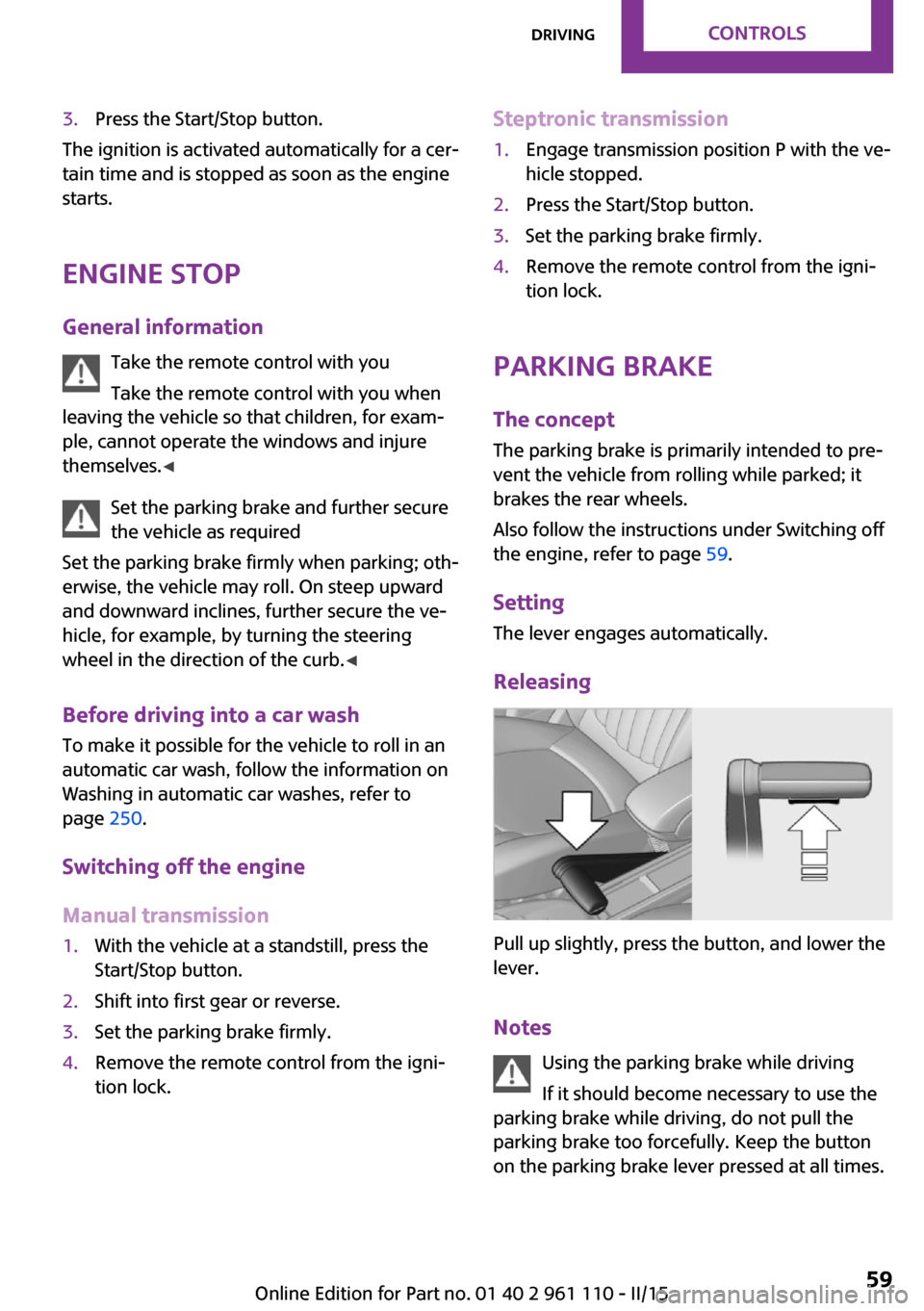
Setting The lever engages automatically.
Releasing
Pull up slightly, press the button, and lower the
lever.
Notes Using the parking brake while driving
If it should become necessary to use the
parking brake while driving, do not pull the
parking brake too forcefully. Keep the button
on the parking brake lever pressed at all times.
Seite 59DrivingCONTROLS59
Online Edition for Part no. 01 40 2 961 110 - II/15
Page 87 of 283
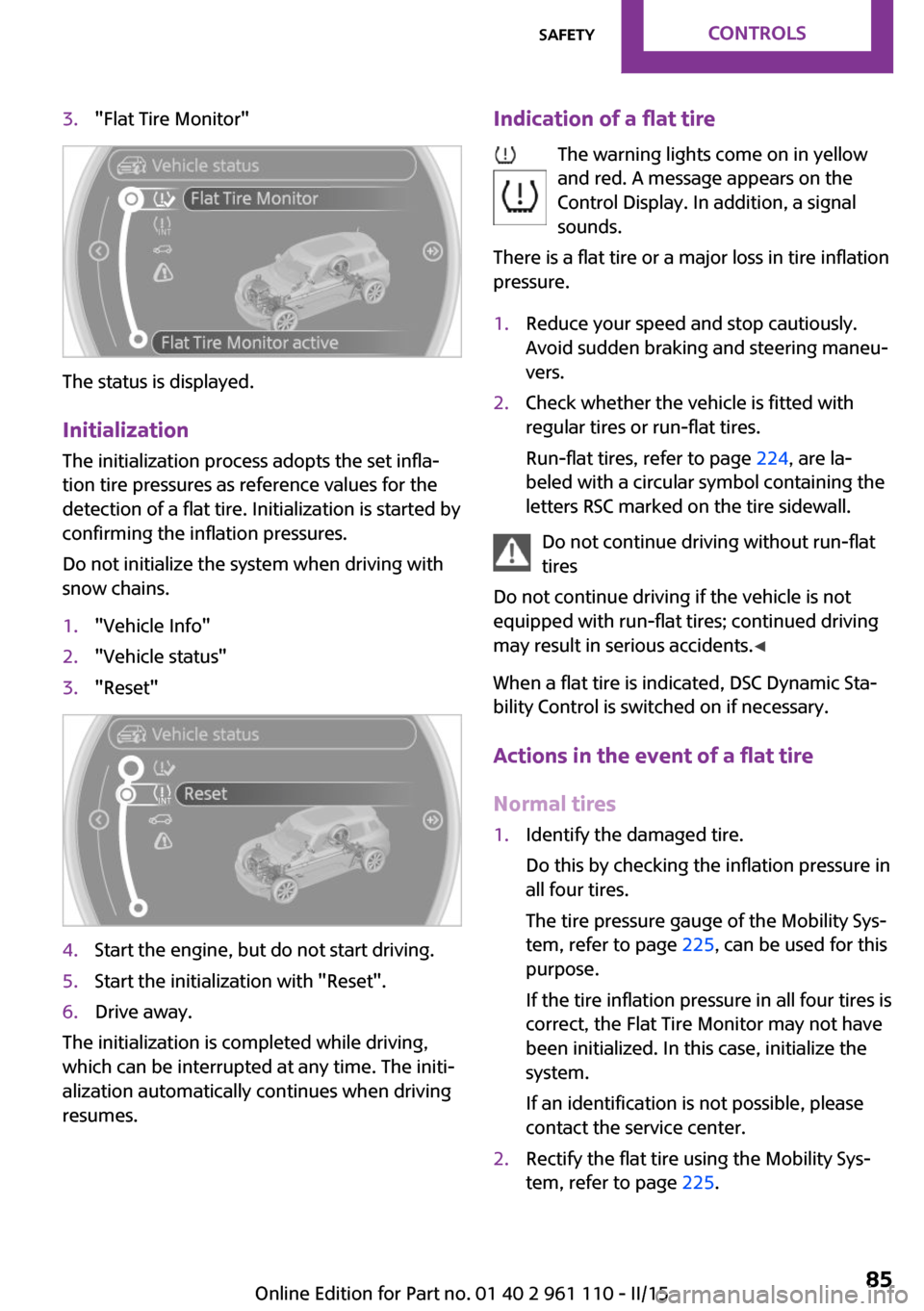
3."Flat Tire Monitor"
The status is displayed.
Initialization The initialization process adopts the set infla‐
tion tire pressures as reference values for the
detection of a flat tire. Initialization is started by
confirming the inflation pressures.
Do not initialize the system when driving with
snow chains.
1."Vehicle Info"2."Vehicle status"3."Reset"4.Start the engine, but do not start driving.5.Start the initialization with "Reset".6.Drive away.
The initialization is completed while driving,
which can be interrupted at any time. The initi‐
alization automatically continues when driving
resumes.
Indication of a flat tire
The warning lights come on in yellow
and red. A message appears on the
Control Display. In addition, a signal
sounds.
There is a flat tire or a major loss in tire inflation
pressure.1.Reduce your speed and stop cautiously.
Avoid sudden braking and steering maneu‐
vers.2.Check whether the vehicle is fitted with
regular tires or run-flat tires.
Run-flat tires, refer to page 224, are la‐
beled with a circular symbol containing the
letters RSC marked on the tire sidewall.
Do not continue driving without run-flat
tires
Do not continue driving if the vehicle is not
equipped with run-flat tires; continued driving
may result in serious accidents. ◀
When a flat tire is indicated, DSC Dynamic Sta‐
bility Control is switched on if necessary.
Actions in the event of a flat tire
Normal tires
1.Identify the damaged tire.
Do this by checking the inflation pressure in
all four tires.
The tire pressure gauge of the Mobility Sys‐
tem, refer to page 225, can be used for this
purpose.
If the tire inflation pressure in all four tires is
correct, the Flat Tire Monitor may not have
been initialized. In this case, initialize the
system.
If an identification is not possible, please
contact the service center.2.Rectify the flat tire using the Mobility Sys‐
tem, refer to page 225.Seite 85SafetyCONTROLS85
Online Edition for Part no. 01 40 2 961 110 - II/15
Page 92 of 283
Declaration according to NHTSA/FMVSS
138 Tire Pressure Monitoring Systems
Each tire, including the spare (if provided)
should be checked monthly when cold and in‐
flated to the inflation pressure recommended
by the vehicle manufacturer on the vehicle
placard or tire inflation pressure label (If your
vehicle has tires of a different size than the size indicated on the vehicle placard or tire inflation
pressure label, you should determine the
proper tire inflation pressure for those tires.).
As an added safety feature, your vehicle has
been equipped with a tire pressure monitoring
system (TPMS) that illuminates a low tire pres‐
sure telltale when one or more of your tires is
significantly under-inflated. Accordingly, when
the low tire pressure telltale illuminates, you
should stop and check your tires as soon as
possible, and inflate them to the proper pres‐
sure. Driving on a significantly under-inflated
tire causes the tire to overheat and can lead to
tire failure. Under-inflation also reduces fuel ef‐
ficiency and tire tread life, and may affect the
vehicle's handling and stopping ability.
Please note that the TPMS is not a substitute for proper tire maintenance, and it is the driver's
responsibility to maintain correct tire pressure,
even if under-inflation has not reached the
level to trigger illumination of the TPMS low tire
pressure telltale.
Your vehicle has also been equipped with a
TPMS malfunction indicator to indicate when
the system is not operating properly. The TPMS
malfunction indicator is combined with the low
tire pressure telltale. When the system detects
a malfunction, the telltale will flash for approxi‐
mately one minute and then remain continu‐
ously illuminated. This sequence will continue
upon subsequent vehicle startups as long as
the malfunction exists. When the malfunction
indicator is illuminated, the system may not be
able to detect or signal low tire pressure as in‐
tended. TPMS malfunctions may occur for a va‐
riety of reasons, including the installation of re‐
placement or alternate tires or wheels on thevehicle that prevent the TPMS from functioning
properly. Always check the TPMS malfunction
telltale after replacing one or more tires or
wheels on your vehicle to ensure that the re‐
placement or alternate tires and wheels allow
the TPMS to continue to function properly.
Speed limit The concept
Enter a speed for which a Check Control mes‐
sage will be displayed when the speed is
reached. This enables you to receive warnings if
you exceed a speed limit in an urban area, for
example.
You are only warned of reaching this speed a
second time if your vehicle speed falls below it
again by at least 3 mph/5 km/h.
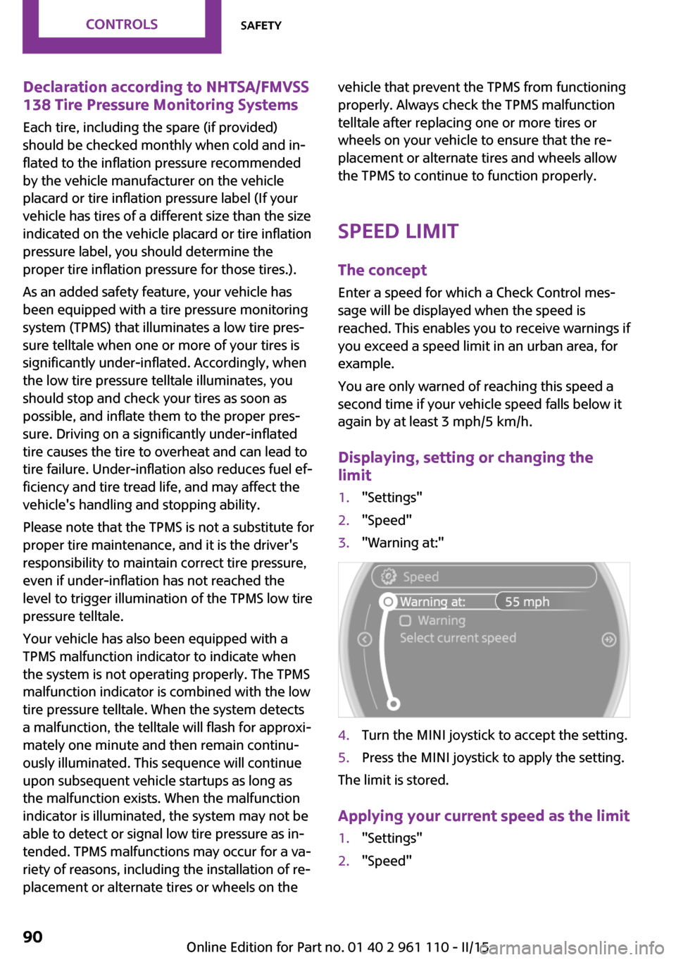
Displaying, setting or changing the
limit1."Settings"2."Speed"3."Warning at:"4.Turn the MINI joystick to accept the setting.5.Press the MINI joystick to apply the setting.
The limit is stored.
Applying your current speed as the limit
1."Settings"2."Speed"Seite 90CONTROLSSafety90
Online Edition for Part no. 01 40 2 961 110 - II/15
Page 145 of 283
Destination guidanceVehicle equipmentThis chapter describes all series equipment as
well as country-specific and special equipment
offered for this model series. Therefore, it also
describes equipment that may not be found in
your vehicle, for instance due to the selected
special equipment or the country version. This
also applies to safety-related functions and sys‐
tems.
When using the features and systems described
here, adhere to local regulations.
Starting destination
guidance1."Navigation"2.Make a destination entry, refer to
page 134.3."Accept destination"4."Start guidance"
The route is shown on the Control Display.
The distance to the destination/intermediate
destination and the estimated time of arrival
are displayed in the map view.
The arrow view may appear on the Control Dis‐
play.
Terminating destination
guidance
1."Navigation"2."Map"3. Select the symbol.4."Stop guidance"Continuing destination
guidance
If the destination was not reached during the
last trip, destination guidance can be resumed.
"Resume guidance"
Route criteria
General information▷The route calculated can be influenced by
selecting certain criteria.▷The route criteria can be changed when the
destination is entered and during destina‐
tion guidance.▷Road types are part of the navigation data
and are taken into consideration when
planning a route, e.g., avoid highways.▷The recommended route may differ from
the route you would take based on per‐
sonal experience.▷The settings are stored for the remote con‐
trol currently in use.▷Destination guidance with traffic bulletins,
refer to page 149.
Changing the route criteria
1."Navigation"2."Map"3. "Route preference"4.Select the criterion:▷ "Fast route": time-optimized route,
being a combination of the shortest
possible route and the fastest roads.▷ "Efficient route": optimized combi‐
nation of the fastest and shortest route.Seite 143Destination guidanceNAVIGATION143
Online Edition for Part no. 01 40 2 961 110 - II/15
Page 250 of 283
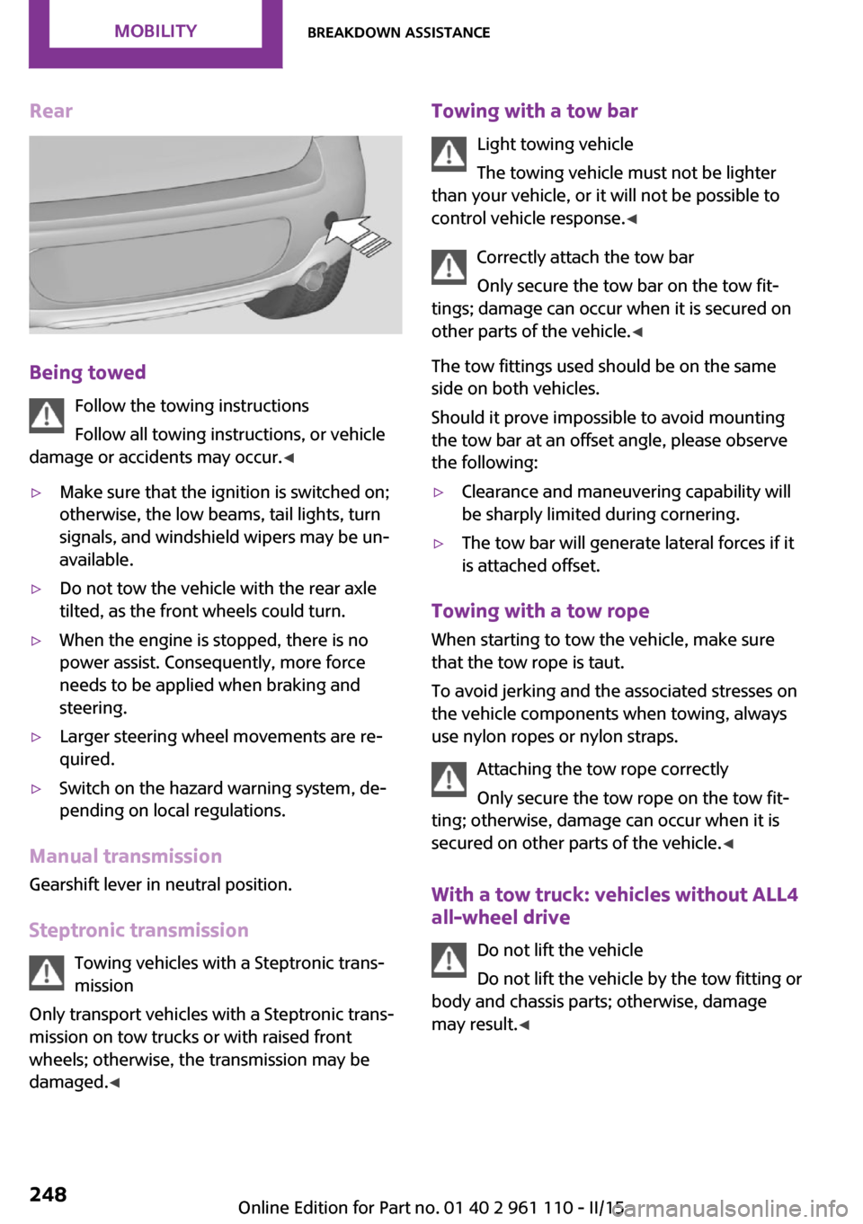
Rear
Being towedFollow the towing instructions
Follow all towing instructions, or vehicle
damage or accidents may occur. ◀
▷Make sure that the ignition is switched on;
otherwise, the low beams, tail lights, turn
signals, and windshield wipers may be un‐
available.▷Do not tow the vehicle with the rear axle
tilted, as the front wheels could turn.▷When the engine is stopped, there is no
power assist. Consequently, more force
needs to be applied when braking and
steering.▷Larger steering wheel movements are re‐
quired.▷Switch on the hazard warning system, de‐
pending on local regulations.
Manual transmission
Gearshift lever in neutral position.
Steptronic transmission Towing vehicles with a Steptronic trans‐
mission
Only transport vehicles with a Steptronic trans‐
mission on tow trucks or with raised front
wheels; otherwise, the transmission may be
damaged. ◀
Towing with a tow bar
Light towing vehicle
The towing vehicle must not be lighter
than your vehicle, or it will not be possible to
control vehicle response. ◀
Correctly attach the tow bar
Only secure the tow bar on the tow fit‐
tings; damage can occur when it is secured on
other parts of the vehicle. ◀
The tow fittings used should be on the same
side on both vehicles.
Should it prove impossible to avoid mounting
the tow bar at an offset angle, please observe
the following:▷Clearance and maneuvering capability will
be sharply limited during cornering.▷The tow bar will generate lateral forces if it
is attached offset.
Towing with a tow rope
When starting to tow the vehicle, make sure
that the tow rope is taut.
To avoid jerking and the associated stresses on
the vehicle components when towing, always
use nylon ropes or nylon straps.
Attaching the tow rope correctly
Only secure the tow rope on the tow fit‐
ting; otherwise, damage can occur when it is
secured on other parts of the vehicle. ◀
With a tow truck: vehicles without ALL4
all-wheel drive
Do not lift the vehicle
Do not lift the vehicle by the tow fitting or
body and chassis parts; otherwise, damage
may result. ◀
Seite 248MOBILITYBreakdown assistance248
Online Edition for Part no. 01 40 2 961 110 - II/15
Page 251 of 283
MINI Countryman:
MINI Paceman:
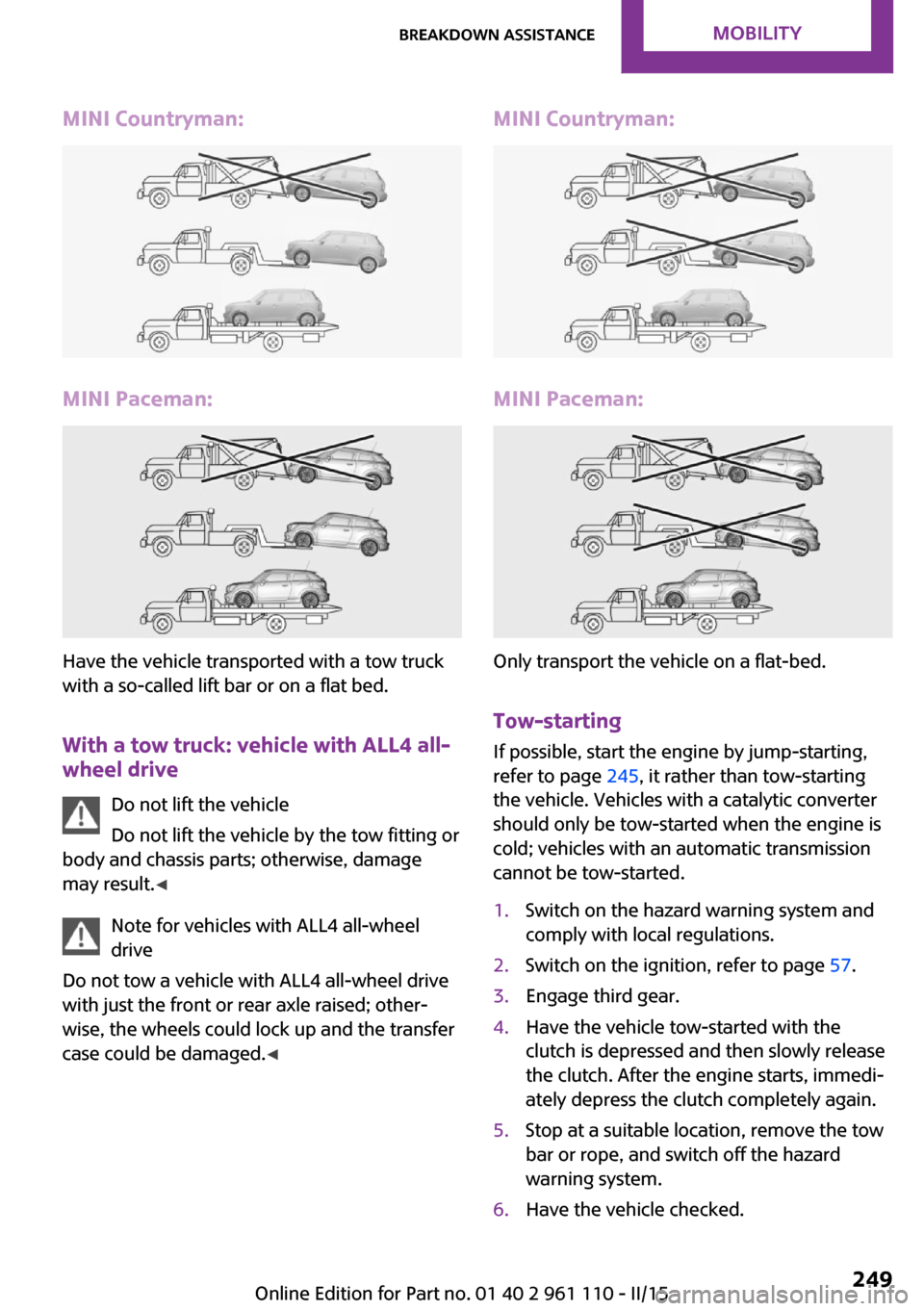
Have the vehicle transported with a tow truck
with a so-called lift bar or on a flat bed.
With a tow truck: vehicle with ALL4 all-wheel drive
Do not lift the vehicle
Do not lift the vehicle by the tow fitting or
body and chassis parts; otherwise, damage
may result. ◀
Note for vehicles with ALL4 all-wheel
drive
Do not tow a vehicle with ALL4 all-wheel drive
with just the front or rear axle raised; other‐
wise, the wheels could lock up and the transfer
case could be damaged. ◀
MINI Countryman:
MINI Paceman:
Only transport the vehicle on a flat-bed.
Tow-starting
If possible, start the engine by jump-starting,
refer to page 245, it rather than tow-starting
the vehicle. Vehicles with a catalytic converter
should only be tow-started when the engine is
cold; vehicles with an automatic transmission
cannot be tow-started.
1.Switch on the hazard warning system and
comply with local regulations.2.Switch on the ignition, refer to page 57.3.Engage third gear.4.Have the vehicle tow-started with the
clutch is depressed and then slowly release
the clutch. After the engine starts, immedi‐
ately depress the clutch completely again.5.Stop at a suitable location, remove the tow
bar or rope, and switch off the hazard
warning system.6.Have the vehicle checked.Seite 249Breakdown assistanceMOBILITY249
Online Edition for Part no. 01 40 2 961 110 - II/15