steering wheel MINI Countryman 2015 Owner's Manual
[x] Cancel search | Manufacturer: MINI, Model Year: 2015, Model line: Countryman, Model: MINI Countryman 2015Pages: 223, PDF Size: 5.46 MB
Page 14 of 223
CockpitVehicle equipment
This chapter describes all series equipment as
well as country-specific and special equipment
offered for this model series. Therefore, it also
describes equipment that may not be found in
your vehicle, for instance due to the selectedspecial equipment or the country version. This
also applies to safety-related functions and sys‐
tems.
When using the features and systems described
here, adhere to local regulations.
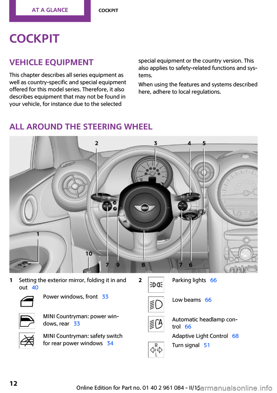
All around the steering wheel
1Setting the exterior mirror, folding it in and
out 40Power windows, front 33MINI Countryman: power win‐
dows, rear 33MINI Countryman: safety switch
for rear power windows 342Parking lights 66Low beams 66Automatic headlamp con‐
trol 66
Adaptive Light Control 68Turn signal 51Seite 12AT A GLANCECockpit12
Online Edition for Part no. 01 40 2 961 084 - II/15
Page 15 of 223
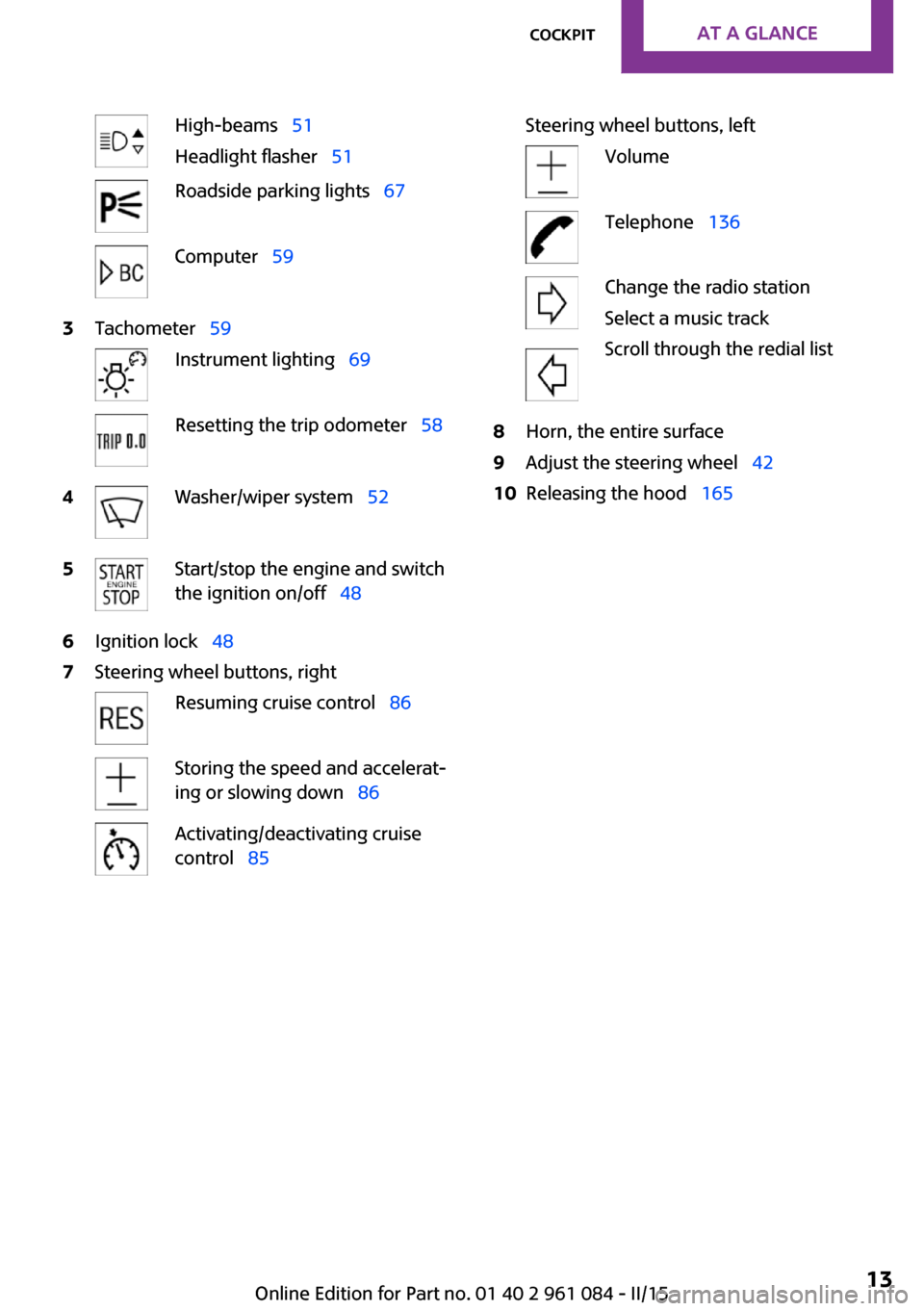
High-beams 51
Headlight flasher 51Roadside parking lights 67Computer 593Tachometer 59Instrument lighting 69Resetting the trip odometer 584Washer/wiper system 525Start/stop the engine and switch
the ignition on/off 486Ignition lock 487Steering wheel buttons, rightResuming cruise control 86Storing the speed and accelerat‐
ing or slowing down 86Activating/deactivating cruise
control 85Steering wheel buttons, leftVolumeTelephone 136Change the radio station
Select a music track
Scroll through the redial list8Horn, the entire surface9Adjust the steering wheel 4210Releasing the hood 165Seite 13CockpitAT A GLANCE13
Online Edition for Part no. 01 40 2 961 084 - II/15
Page 44 of 223

▷Do not cover the area between the inside
rearview mirror and the windshield.▷Do not apply stickers to the windshield in
front of the mirror.
Steering wheel
Adjusting Do not adjust while driving
Do not adjust the steering wheel while
driving; otherwise, an unexpected movement
could result in an accident. ◀
1.Fold the lever down.2.Move the steering wheel to the preferred
height and angle to suit your seating posi‐
tion.3.Fold the lever back.
Do not use force to swing the lever back.
Do not use force to swing the lever back
up; otherwise, the mechanism will be dam‐
aged. ◀
Seite 42CONTROLSAdjusting42
Online Edition for Part no. 01 40 2 961 084 - II/15
Page 52 of 223
3.Press the Start/Stop button.
The ignition is activated automatically for a cer‐
tain time and is stopped as soon as the engine
starts.
Engine stop
General information Take the remote control with you
Take the remote control with you when
leaving the vehicle so that children, for exam‐
ple, cannot operate the windows and injure
themselves. ◀
Set the parking brake and further secure
the vehicle as required
Set the parking brake firmly when parking; oth‐
erwise, the vehicle may roll. On steep upward
and downward inclines, further secure the ve‐
hicle, for example, by turning the steering
wheel in the direction of the curb. ◀
Before driving into a car wash To make it possible for the vehicle to roll in an
automatic car wash, follow the information on
Washing in automatic car washes, refer to
page 186.
Switching off the engine
Manual transmission
1.With the vehicle at a standstill, press the
Start/Stop button.2.Shift into first gear or reverse.3.Set the parking brake firmly.4.Remove the remote control from the igni‐
tion lock.Steptronic transmission1.Engage transmission position P with the ve‐
hicle stopped.2.Press the Start/Stop button.3.Set the parking brake firmly.4.Remove the remote control from the igni‐
tion lock.
Parking brake
The concept
The parking brake is primarily intended to pre‐
vent the vehicle from rolling while parked; it
brakes the rear wheels.
Also follow the instructions under Switching off
the engine, refer to page 50.
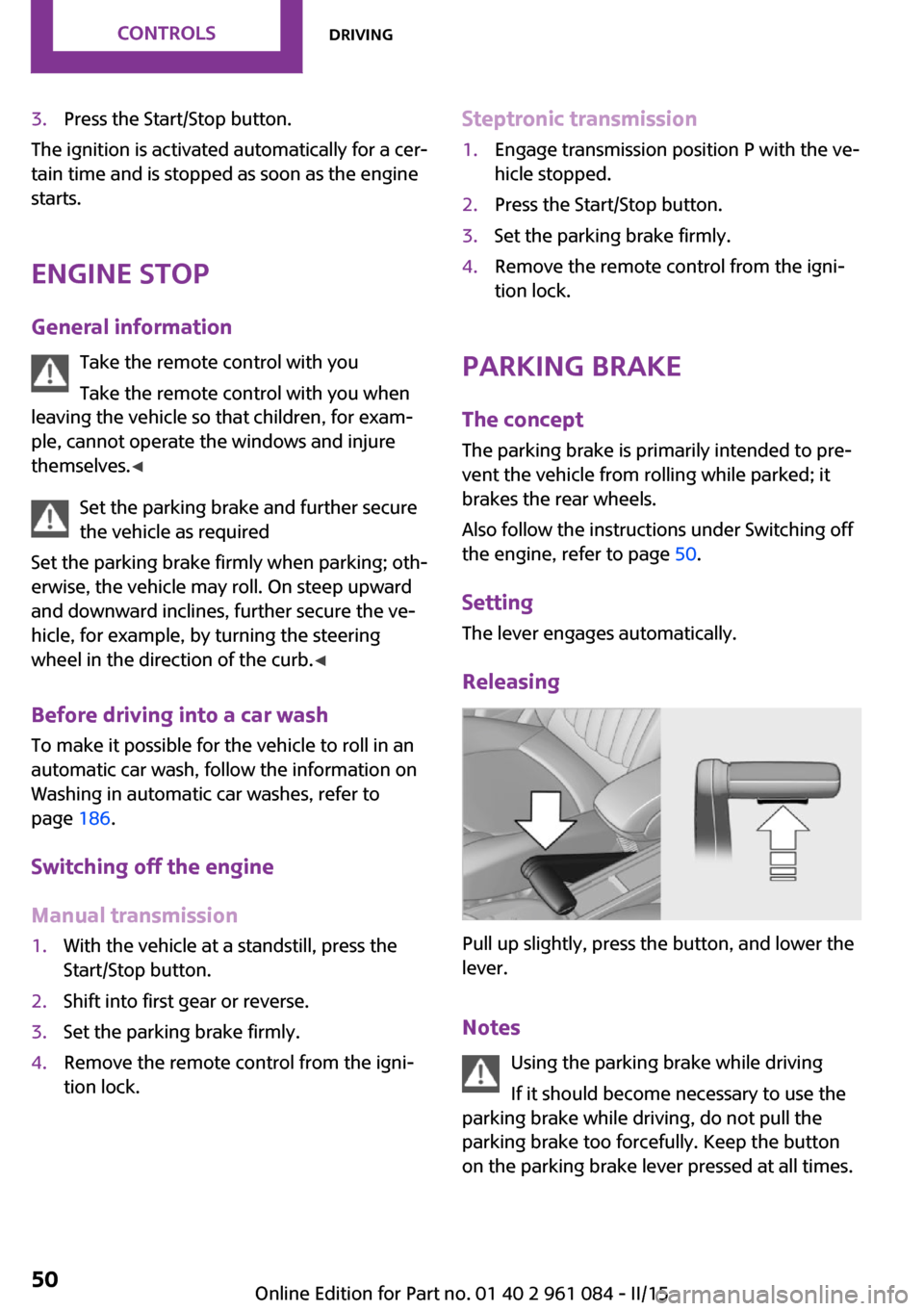
Setting The lever engages automatically.
Releasing
Pull up slightly, press the button, and lower the
lever.
Notes Using the parking brake while driving
If it should become necessary to use the
parking brake while driving, do not pull the
parking brake too forcefully. Keep the button
on the parking brake lever pressed at all times.
Seite 50CONTROLSDriving50
Online Edition for Part no. 01 40 2 961 084 - II/15
Page 59 of 223

The vehicle only shifts up or down at appropri‐
ate engine and road speeds, e.g., it does not
shift down if the engine speed is too high. The
selected gear is briefly displayed in the instru‐
ment panel, followed by the current gear.
Shifting gears using the shift paddleson the steering wheel
The shift paddles on the steering wheel allow
you to shift gears quickly while keeping both hands on the steering wheel.▷When the shift paddles on the steering
wheel are used to shift gears while in auto‐
matic mode, the transmission switches to
manual mode.▷If the shift paddles are not used to acceler‐
ate or shift gears for a certain amount of
time, the transmission switches back to au‐
tomatic mode.
If the selector lever is in the M/S gear plane,
manual mode remains active.
▷Pull one of the two shift paddles:
The transmission shifts up.▷Press one of the two shift paddles:
The transmission shifts down.
The vehicle only shifts up or down at appropri‐
ate engine and road speeds, e.g., it does not
shift down if the engine speed is too high. The
selected gear is briefly displayed in the instru‐
ment panel, followed by the current gear.
Manually unlocking the selector lever
lock
If the selector lever is locked in position P al‐
though the ignition is switched on, the brake is
depressed, and the button on the selector lever
is pressed, the selector lever lock can be over‐
ridden:1.Switch off the ignition.2.Unclip the sleeve of the selector lever.3.Pull the sleeve up over the selector lever
until the sleeve is inside out.
Pull off the plug-in cable connector if nec‐
essary.4.Insert the pulling hook 1 into the loop on
the passenger side.
The pulling hook is found in the vehicle
document portfolio or in the pouch of the
wheel change set, refer to page 178.5.Pull the loop upward.6.Move the selector lever into the desired po‐
sition, pressing the button on the front of
the selector lever.
Set the parking brake
Manually unlock the selector lever lock
for towing only. Before manually unlocking the
selector lever lock, pull the parking brake
firmly; otherwise, the vehicle may roll away and
cause personal injury or property damage. ◀
Seite 57DrivingCONTROLS57
Online Edition for Part no. 01 40 2 961 084 - II/15
Page 74 of 223
Protective action
Airbags are not triggered in every impact situa‐
tion, e.g., in less severe accidents or rear-end
collisions.
Information on how to ensure the opti‐
mal protective effect of the airbags▷Keep at a distance from the airbags.▷Always grasp the steering wheel on the
steering wheel rim, holding your hands at
the 3 o'clock and 9 o'clock positions, to
keep the danger of injury to your hands or
arms as low as possible if the airbag is trig‐
gered.▷There should be no people, animals, or ob‐
jects between an airbag and a person.▷Do not use the cover of the front airbag on
the front passenger side as a storage area.▷Keep the dashboard and window on the
front passenger side clear, i.e., do not cover
with adhesive labels or coverings, and do
not attach holders or cables such as for
navigation instruments and mobile phones.▷Make sure that the front passenger is sitting
correctly, i.e., keeps his or her feet and legs
in the footwell; otherwise, leg injuries can
occur if the front airbag is triggered.▷Do not place slip covers, seat cushions or
other objects on the front passenger seat
that are not approved specifically for seats
with integrated side airbags.▷Do not hang pieces of clothing, such as
jackets, over the backrests.▷Make sure that occupants keep their heads
away from the side airbag and do not rest
against the head airbag; otherwise, injuries
can occur if the airbags are triggered.▷Do not remove the airbag restraint system.▷Do not remove the steering wheel.▷Do not apply adhesive materials to the air‐
bag cover panels, cover them or modify
them in any way.▷Never modify either the individual compo‐
nents or the wiring in the airbag system.
This also applies to steering wheel covers,
the dashboard, the seats, the roof pillars
and the sides of the headliner. ◀
Even when all instructions are followed closely,
injury from contact with the airbags cannot be
ruled out in certain situations.
The ignition and inflation noise may lead to
short-term and, in most cases, temporary hear‐
ing impairment in sensitive individuals.
In the case of a malfunction, deactivation
and after triggering of the airbags
Do not touch the individual components imme‐
diately after the system has been triggered;
otherwise, there is the danger of burns.
Only have the airbags checked, repaired or dis‐
mantled and the airbag generator scrapped by
your service center or a workshop that has the
necessary authorization for handling explo‐
sives.
Non-professional attempts to service the sys‐
tem could lead to failure in an emergency or
undesired triggering of the airbag, either of
which could result in injury. ◀
Warning notices and information about the air‐
bags can also be found on the sun visors.
Automatic deactivation of the front
passenger airbags
The system determines whether the front pas‐
senger seat is occupied by measuring the elec‐
trical resistance of the human body.
The front, side, and knee airbags on the front
passenger side are activated or deactivated ac‐
cordingly by the system.
The indicator lamp above the interior rearview
mirror, refer to page 73, shows the current
status of the front passenger airbags, deacti‐
vated or activated.
Seite 72CONTROLSSafety72
Online Edition for Part no. 01 40 2 961 084 - II/15
Page 78 of 223
Continued driving with a flat tire
If continuing to drive with a damaged tire:1.Avoid sudden braking and steering maneu‐
vers.2.Do not exceed a speed of 50 mph/80 km/h.3.At the next opportunity, check the inflation
pressure in all four tires.
If the tire inflation pressure in all four tires is
correct, the Flat Tire Monitor may not have
been initialized. In this case, initialize the
system.
Possible driving distance with complete loss of
tire inflation pressure:
The possible driving distance after a loss of tire
inflation pressure depends on the cargo load
and the driving style and conditions.
For a vehicle containing an average load, the
possible driving distance is ap‐
prox. 50 miles/80 km.
When the vehicle is driven with a damaged tire,
its handling characteristics change, e.g., re‐
duced lane stability during braking, a longer
braking distance, and altered self-steering
properties. Adjust your driving style accord‐
ingly. Avoid abrupt steering maneuvers or driv‐
ing over obstacles, e. g., curbs, potholes, etc.
Because the possible driving distance depends
on how the vehicle is used during the trip, the
actual distance may be smaller or greater de‐
pending on the driving speed, road conditions,
external temperature, cargo load, etc.
Continued driving with a flat tire
Drive moderately and do not exceed a
speed of 50 mph/80 km/h.
A loss of tire inflation pressure results in a
change in the handling characteristics, e.g., re‐
duced lane stability during braking, a longer
braking distance and altered self-steering prop‐
erties. ◀
Final tire failure
Vibrations or loud noises while driving
can indicate the final failure of the tire. Reduce
speed and stop; otherwise, pieces of the tire
could come loose and cause an accident. Do
not continue driving, and contact your service
center. ◀
Tire Pressure Monitor
TPM
The concept
The system monitors the tire pressure in the
four mounted tires. The system notifies you if
there is a significant loss of pressure in one or
more tires. Sensors in the tire valves measure
the tire pressure.
Notes Tire damage caused by external influen‐
ces
Sudden tire damage caused by external influ‐
ences cannot be indicated in advance. ◀
To operate the system, also note the additional
information and instructions contained under
Tire inflation pressure, refer to page 152.
Functional requirements
The system must have been reset while the in‐
flation pressure was correct; otherwise, it may
not reliably signal a loss in pressure.
Perform a system reset after adjusting the tire
inflation pressure to a new value and after
changing a tire or wheel
Always use wheels with TPM electronics to en‐
sure that the system will operate properly.Seite 76CONTROLSSafety76
Online Edition for Part no. 01 40 2 961 084 - II/15
Page 79 of 223
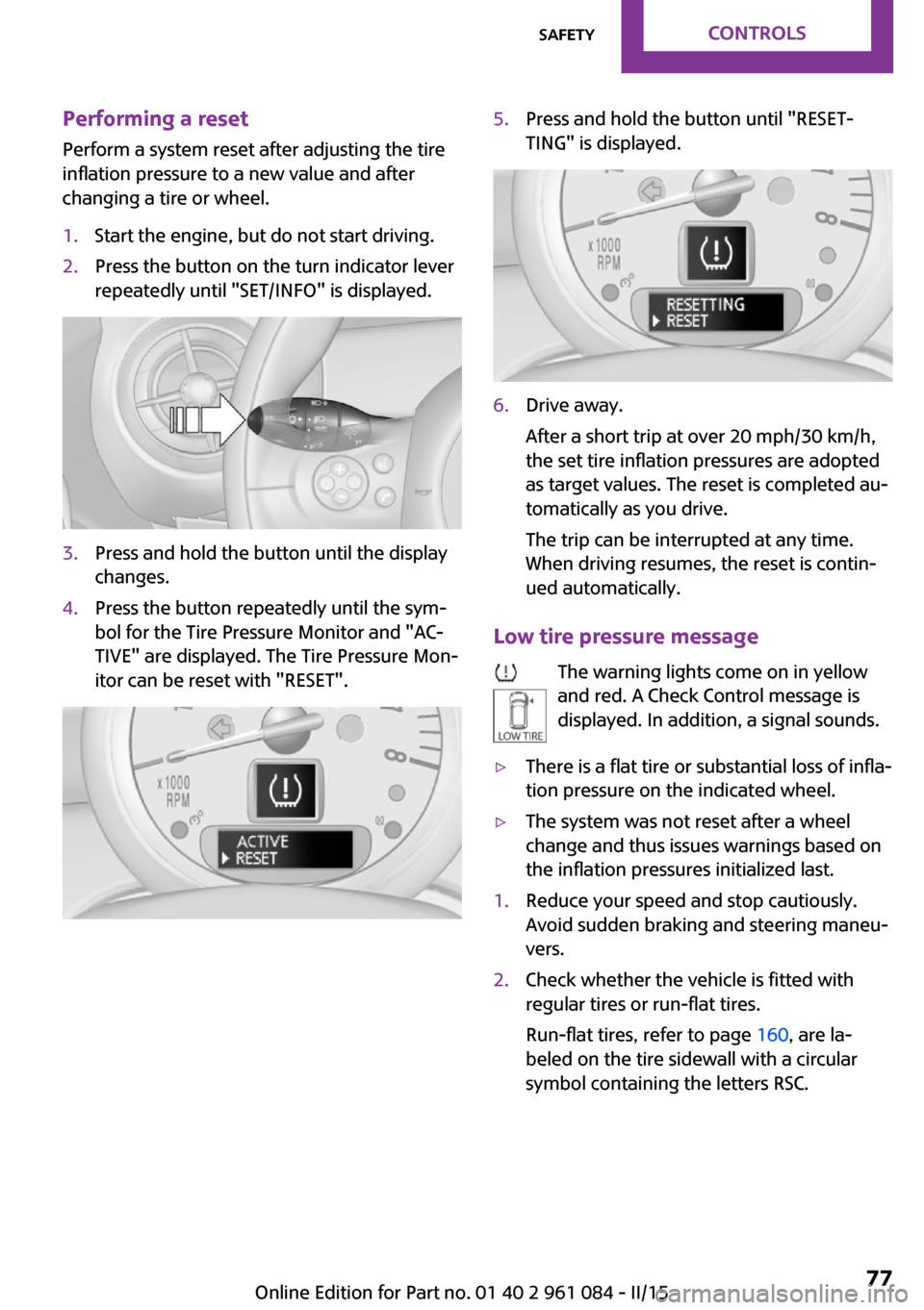
Performing a reset
Perform a system reset after adjusting the tire
inflation pressure to a new value and after
changing a tire or wheel.1.Start the engine, but do not start driving.2.Press the button on the turn indicator lever
repeatedly until "SET/INFO" is displayed.3.Press and hold the button until the display
changes.4.Press the button repeatedly until the sym‐
bol for the Tire Pressure Monitor and "AC‐
TIVE" are displayed. The Tire Pressure Mon‐
itor can be reset with "RESET".5.Press and hold the button until "RESET‐
TING" is displayed.6.Drive away.
After a short trip at over 20 mph/30 km/h,
the set tire inflation pressures are adopted
as target values. The reset is completed au‐
tomatically as you drive.
The trip can be interrupted at any time.
When driving resumes, the reset is contin‐
ued automatically.
Low tire pressure message
The warning lights come on in yellow
and red. A Check Control message is
displayed. In addition, a signal sounds.
▷There is a flat tire or substantial loss of infla‐
tion pressure on the indicated wheel.▷The system was not reset after a wheel
change and thus issues warnings based on
the inflation pressures initialized last.1.Reduce your speed and stop cautiously.
Avoid sudden braking and steering maneu‐
vers.2.Check whether the vehicle is fitted with
regular tires or run-flat tires.
Run-flat tires, refer to page 160, are la‐
beled on the tire sidewall with a circular
symbol containing the letters RSC.Seite 77SafetyCONTROLS77
Online Edition for Part no. 01 40 2 961 084 - II/15
Page 80 of 223

Do not continue driving without run-flat
tires
Do not continue driving if the vehicle is not
equipped with run-flat tires; continued driving
may result in serious accidents. ◀
When a low inflation pressure is indicated, DSC
Dynamic Stability Control is switched on if nec‐
essary.
Actions in the event of a flat tire Normal tires1.Identify the damaged tire.
Do this by checking the air pressure in all
four tires. The tire pressure gauge of the
Mobility System, refer to page 161, can be
used for this purpose.
If the tire inflation pressure in all four tires is
correct, the Tire Pressure Monitor may not
have been reset. Reset the system.
If an identification is not possible, please
contact the service center.2.Rectify the flat tire using the Mobility Sys‐
tem, refer to page 161.
Use of tire sealant, e.g., the Mobility Sys‐
tem, may damage the TPM wheel electron‐
ics. In this case, have the electronics
checked at the next opportunity and have
them replaced if necessary.
Run-flat tires
You can continue driving with a damaged tire
at speeds up to 50 mph/80 km/h.
Do not continue driving without run-flat
tires
Do not continue driving if the vehicle is not
equipped with run-flat tires; continued driving
may result in serious accidents. ◀
Continued driving with a flat tire
If continuing to drive with a damaged tire:1.Avoid sudden braking and steering maneu‐
vers.2.Do not exceed a speed of 50 mph/80 km/h.3.Check the air pressure in all four tires at the
next opportunity.
If the tire inflation pressure in all four tires is
correct, the Tire Pressure Monitor may not
have been reset. Reset the system.
Possible driving distance with complete loss of
tire inflation pressure:
The possible driving distance after a loss of tire
inflation pressure depends on the cargo load
and the driving style and conditions.
For a vehicle containing an average load, the
possible driving distance is ap‐
prox. 50 miles/80 km.
When the vehicle is driven with a damaged tire,
its handling characteristics change, e.g., re‐
duced lane stability during braking, a longer
braking distance, and altered self-steering
properties. Adjust your driving style accord‐
ingly. Avoid abrupt steering maneuvers or driv‐
ing over obstacles, e. g., curbs, potholes, etc.
Because the possible driving distance depends
on how the vehicle is used during the trip, the
actual distance may be smaller or greater de‐
pending on the driving speed, road conditions,
external temperature, cargo load, etc.
Continued driving with a flat tire
Drive moderately and do not exceed a
speed of 50 mph/80 km/h.
A loss of tire inflation pressure results in a
change in the handling characteristics, e.g., re‐
duced lane stability during braking, a longer
braking distance and altered self-steering prop‐
erties. ◀
Seite 78CONTROLSSafety78
Online Edition for Part no. 01 40 2 961 084 - II/15
Page 83 of 223

Driving stability control systemsVehicle equipment
This chapter describes all series equipment as
well as country-specific and special equipment
offered for this model series. Therefore, it also
describes equipment that may not be found in
your vehicle, for instance due to the selected
special equipment or the country version. This
also applies to safety-related functions and sys‐
tems.
When using the features and systems described
here, adhere to local regulations.
Antilock Brake System
ABS
ABS prevents locking of the wheels during braking.
Steerability is maintained even during full brak‐
ing. This increases active driving safety.
ABS is operational every time you start the en‐
gine.
Electronic brake-force distribution EBVThe system controls the brake pressure in the
rear wheels to ensure stable braking behavior.
CBC Cornering Brake Control
When braking in curves or during a lane
change, driving stability and steering response
are improved further.
Brake assistant When the brakes are applied rapidly, this sys‐
tem automatically produces the maximum
braking force boost. In this way, the system
helps keep the braking distance as short aspossible. This system utilizes all of the benefits
provided by ABS.
Do not reduce the pressure on the brake pedal
for the duration of full braking.
Dynamic Stability Con‐ trol DSC
The concept
DSC prevents traction loss in the driving wheels
when driving away and accelerating.
DSC also recognizes unstable vehicle condi‐
tions, such as fishtailing or nose-diving. Subject
to physical limits, DSC helps to keep the vehicle
on a steady course by reducing engine speed
and by applying brakes to the individual
wheels.
DSC is operational every time you start the en‐
gine.
Adjust your driving style to the situation
An appropriate driving style is always the
responsibility of the driver.
The laws of physics cannot be repealed, even
with DSC.
Do not reduce the additional safety margin
with a risky driving style, as otherwise there is a
risk of an accident. ◀Seite 81Driving stability control systemsCONTROLS81
Online Edition for Part no. 01 40 2 961 084 - II/15