wheel MINI COUNTRYMAN PACEMAN 2014 Service Manual
[x] Cancel search | Manufacturer: MINI, Model Year: 2014, Model line: COUNTRYMAN PACEMAN, Model: MINI COUNTRYMAN PACEMAN 2014Pages: 218, PDF Size: 5.45 MB
Page 177 of 218
Replacing
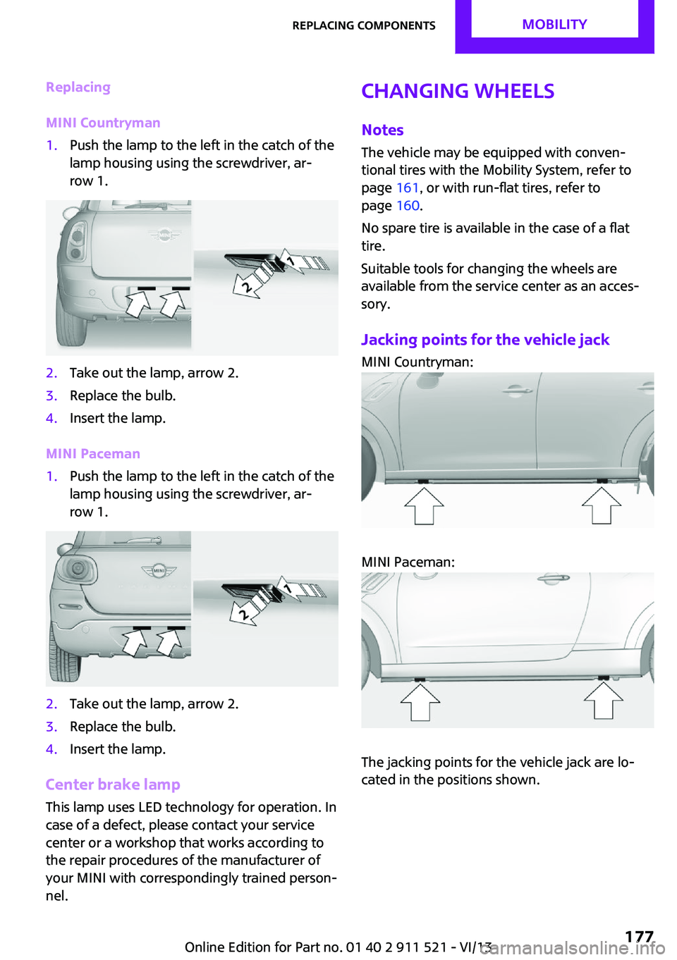
MINI Countryman1.Push the lamp to the left in the catch of the
lamp housing using the screwdriver, ar‐
row 1.2.Take out the lamp, arrow 2.3.Replace the bulb.4.Insert the lamp.
MINI Paceman
1.Push the lamp to the left in the catch of the
lamp housing using the screwdriver, ar‐
row 1.2.Take out the lamp, arrow 2.3.Replace the bulb.4.Insert the lamp.
Center brake lamp
This lamp uses LED technology for operation. In
case of a defect, please contact your service
center or a workshop that works according to
the repair procedures of the manufacturer of
your MINI with correspondingly trained person‐
nel.
Changing wheels
Notes
The vehicle may be equipped with conven‐
tional tires with the Mobility System, refer to
page 161, or with run-flat tires, refer to
page 160.
No spare tire is available in the case of a flat
tire.
Suitable tools for changing the wheels are
available from the service center as an acces‐
sory.
Jacking points for the vehicle jack MINI Countryman:
MINI Paceman:
The jacking points for the vehicle jack are lo‐
cated in the positions shown.
Seite 177Replacing componentsMobility177
Online Edition for Part no. 01 40 2 911 521 - VI/13
Page 182 of 218
the battery, or to the engine or body
ground of the vehicle to be started.
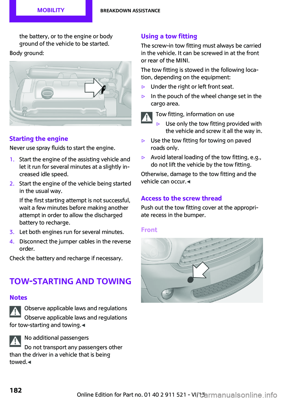
Body ground:
Starting the engine
Never use spray fluids to start the engine.
1.Start the engine of the assisting vehicle and
let it run for several minutes at a slightly in‐
creased idle speed.2.Start the engine of the vehicle being started
in the usual way.
If the first starting attempt is not successful,
wait a few minutes before making another
attempt in order to allow the discharged
battery to recharge.3.Let both engines run for several minutes.4.Disconnect the jumper cables in the reverse
order.
Check the battery and recharge if necessary.
Tow-starting and towing
Notes Observe applicable laws and regulations
Observe applicable laws and regulations
for tow-starting and towing. ◀
No additional passengers
Do not transport any passengers other
than the driver in a vehicle that is being
towed. ◀
Using a tow fitting
The screw-in tow fitting must always be carried
in the vehicle. It can be screwed in at the front
or rear of the MINI.
The tow fitting is stowed in the following loca‐
tion, depending on the equipment:▷Under the right or left front seat.▷In the pouch of the wheel change set in the
cargo area.
Tow fitting, information on use
▷Use only the tow fitting provided with
the vehicle and screw it all the way in.▷Use the tow fitting for towing on paved
roads only.▷Avoid lateral loading of the tow fitting, e.g.,
do not lift the vehicle by the tow fitting.
Otherwise, damage to the tow fitting and the
vehicle can occur. ◀
Access to the screw thread Push out the tow fitting cover at the appropri‐
ate recess in the bumper.
Front
Seite 182MobilityBreakdown assistance182
Online Edition for Part no. 01 40 2 911 521 - VI/13
Page 183 of 218
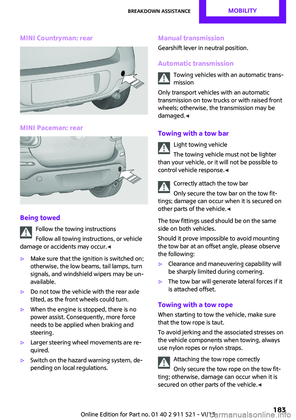
MINI Countryman: rear
MINI Paceman: rear
Being towedFollow the towing instructions
Follow all towing instructions, or vehicle
damage or accidents may occur. ◀
▷Make sure that the ignition is switched on;
otherwise, the low beams, tail lamps, turn
signals, and windshield wipers may be un‐
available.▷Do not tow the vehicle with the rear axle
tilted, as the front wheels could turn.▷When the engine is stopped, there is no
power assist. Consequently, more force
needs to be applied when braking and
steering.▷Larger steering wheel movements are re‐
quired.▷Switch on the hazard warning system, de‐
pending on local regulations.Manual transmission
Gearshift lever in neutral position.
Automatic transmission Towing vehicles with an automatic trans‐
mission
Only transport vehicles with an automatic
transmission on tow trucks or with raised front
wheels; otherwise, the transmission may be
damaged. ◀
Towing with a tow bar Light towing vehicle
The towing vehicle must not be lighter
than your vehicle, or it will not be possible to
control vehicle response. ◀
Correctly attach the tow bar
Only secure the tow bar on the tow fit‐
tings; damage can occur when it is secured on
other parts of the vehicle. ◀
The tow fittings used should be on the same
side on both vehicles.
Should it prove impossible to avoid mounting
the tow bar at an offset angle, please observe
the following:▷Clearance and maneuvering capability will
be sharply limited during cornering.▷The tow bar will generate lateral forces if it
is attached offset.
Towing with a tow rope
When starting to tow the vehicle, make sure
that the tow rope is taut.
To avoid jerking and the associated stresses on
the vehicle components when towing, always
use nylon ropes or nylon straps.
Attaching the tow rope correctly
Only secure the tow rope on the tow fit‐
ting; otherwise, damage can occur when it is
secured on other parts of the vehicle. ◀
Seite 183Breakdown assistanceMobility183
Online Edition for Part no. 01 40 2 911 521 - VI/13
Page 184 of 218
With a tow truck: vehicles without ALL4all-wheel drive
Do not lift the vehicle
Do not lift the vehicle by the tow fitting or
body and chassis parts; otherwise, damage
may result. ◀
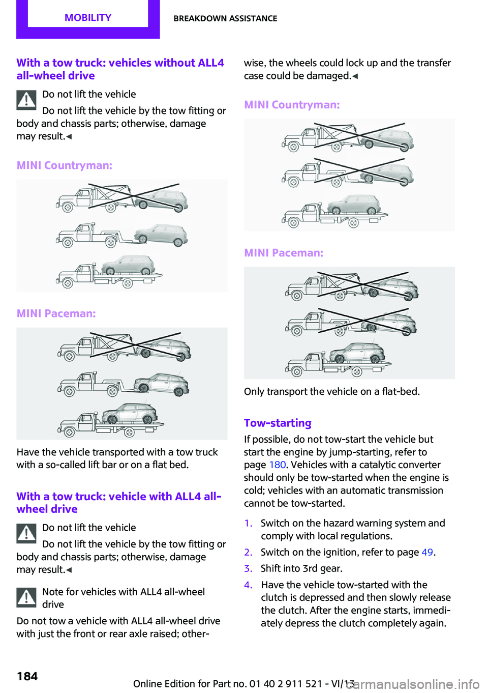
MINI Countryman:
MINI Paceman:
Have the vehicle transported with a tow truck
with a so-called lift bar or on a flat bed.
With a tow truck: vehicle with ALL4 all-wheel drive
Do not lift the vehicle
Do not lift the vehicle by the tow fitting or
body and chassis parts; otherwise, damage
may result. ◀
Note for vehicles with ALL4 all-wheel
drive
Do not tow a vehicle with ALL4 all-wheel drive
with just the front or rear axle raised; other‐
wise, the wheels could lock up and the transfer
case could be damaged. ◀
MINI Countryman:
MINI Paceman:
Only transport the vehicle on a flat-bed.
Tow-starting
If possible, do not tow-start the vehicle but
start the engine by jump-starting, refer to page 180. Vehicles with a catalytic converter
should only be tow-started when the engine is
cold; vehicles with an automatic transmission
cannot be tow-started.
1.Switch on the hazard warning system and
comply with local regulations.2.Switch on the ignition, refer to page 49.3.Shift into 3rd gear.4.Have the vehicle tow-started with the
clutch is depressed and then slowly release
the clutch. After the engine starts, immedi‐
ately depress the clutch completely again.Seite 184MobilityBreakdown assistance184
Online Edition for Part no. 01 40 2 911 521 - VI/13
Page 189 of 218

Chrome surfacesCarefully clean components such as the radia‐
tor grille or door handles with an ample supply
of water, possibly with shampoo added, partic‐
ularly when they have been exposed to road
salt. For additional treatment, use a chrome
polish.
Light-alloy wheels
When cleaning the wheels on the vehicle, only
use a neutral wheel rim cleaner with a pH value
of 5 to 9.
Do not use abrasive cleaners or a steam jet hot‐
ter than 140 ℉/60 ℃; otherwise, damage may
result. Adhere to the manufacturer instructions.
Aggressive, acidic, or alkaline cleaners may de‐
stroy the protective coating of neighboring
components such as the brake disc.
Exterior sensors The sensors on the outside of the vehicle, such
as for Park Distance Control, must be kept clean
and free of ice to ensure that they remain fully
functional.
Decorative trim Clean decorative trims and fine wood compo‐
nents with a moist cloth only. Then dry with a
soft cloth.
Safety belts Dirty belt straps impede the reeling action and
thus have a negative impact on safety.
No chemical cleaning
Do not clean chemically; this can destroy
the webbing. ◀
Carpets/floor mats No objects in the area around the pedals
Keep floor mats, carpets, and any other
objects out of the area of motion of the pedals;
otherwise, the function of the pedals could be
impeded while drivingDo not place additional floor mats over existing
mats or other objects.
Only use floor mats that have been approved
for the vehicle and can be properly fixed in
place.
Ensure that the floor mats are securely fastened
again when they are returned after being re‐
moved, such as for cleaning. ◀
Floor mats can be removed for cleaning.
If they are very dirty, clean with a microfiber
cloth and water or an interior cleaner. To pre‐
vent matting of the carpet, rub back and forth
in the direction of travel only.
Displays
To clean the displays, such as the radio or dis‐
play elements, use an antistatic microfiber
cloth.
Cleaning displays
Do not use chemical or household cleans‐
ers.
Keep all fluids and moisture away from the
unit.
Otherwise, they could affect or damage surfa‐
ces or electrical components.
Avoid pressing too hard when cleaning and do
not use abrasive materials; otherwise, damage
can result. ◀
CD/DVD drives No cleaning CD
Do not use cleaning CDs; otherwise, parts
of the drive may become damaged. ◀
Long-term vehicle storage
Your service center can advise you on what to
consider when storing the vehicle for longer
than three months.Seite 189CareMobility189
Online Edition for Part no. 01 40 2 911 521 - VI/13
Page 196 of 218
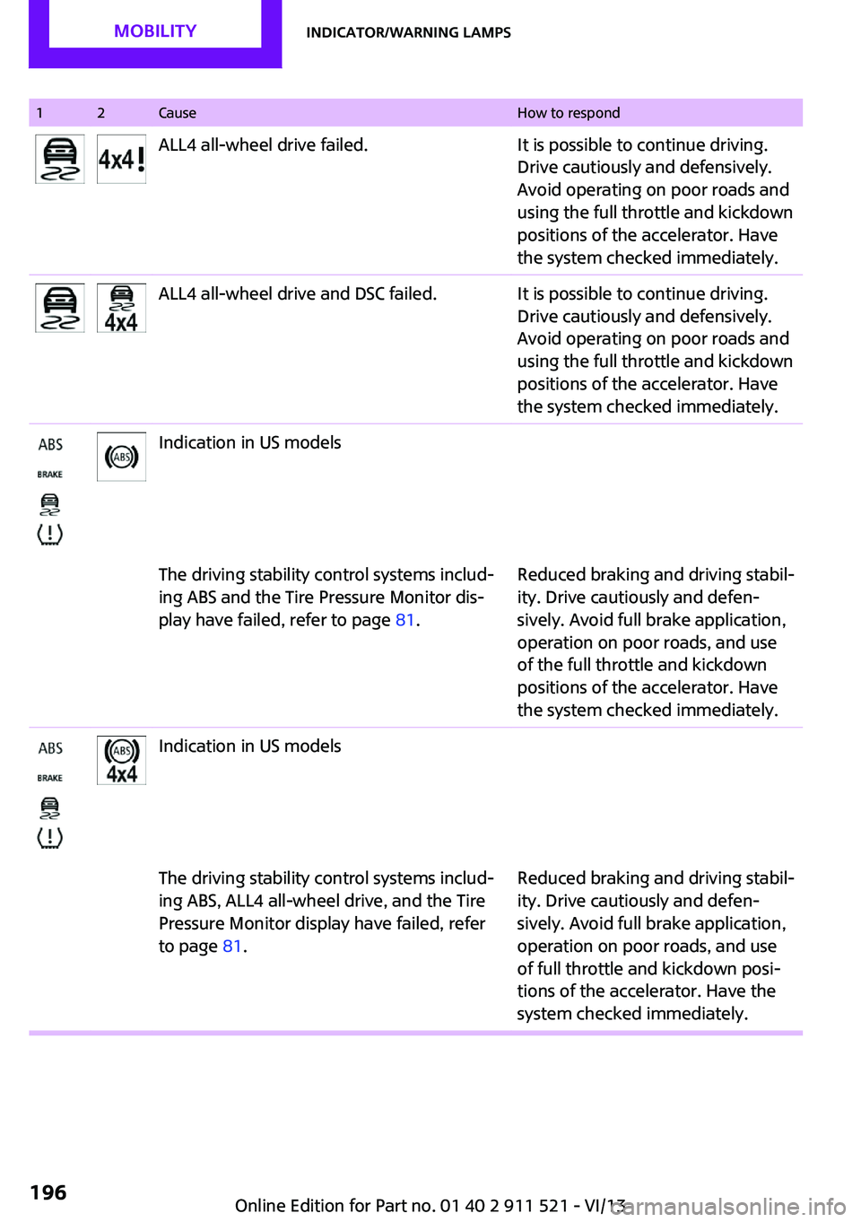
12CauseHow to respondALL4 all-wheel drive failed.It is possible to continue driving.
Drive cautiously and defensively.
Avoid operating on poor roads and
using the full throttle and kickdown
positions of the accelerator. Have
the system checked immediately.ALL4 all-wheel drive and DSC failed.It is possible to continue driving.
Drive cautiously and defensively.
Avoid operating on poor roads and
using the full throttle and kickdown
positions of the accelerator. Have
the system checked immediately.Indication in US modelsThe driving stability control systems includ‐
ing ABS and the Tire Pressure Monitor dis‐
play have failed, refer to page 81.Reduced braking and driving stabil‐
ity. Drive cautiously and defen‐
sively. Avoid full brake application,
operation on poor roads, and use
of the full throttle and kickdown
positions of the accelerator. Have
the system checked immediately.Indication in US modelsThe driving stability control systems includ‐
ing ABS, ALL4 all-wheel drive, and the Tire
Pressure Monitor display have failed, refer
to page 81.Reduced braking and driving stabil‐
ity. Drive cautiously and defen‐
sively. Avoid full brake application,
operation on poor roads, and use
of full throttle and kickdown posi‐
tions of the accelerator. Have the
system checked immediately.Seite 196MobilityIndicator/warning lamps196
Online Edition for Part no. 01 40 2 911 521 - VI/13
Page 197 of 218

12CauseHow to respondIndication in Canadian modelsThe driving stability control systems includ‐
ing ABS and the Flat Tire Monitor or the Tire
Pressure Monitor have failed, refer to
page 81.Reduced braking and driving stabil‐
ity. Drive cautiously and defen‐
sively. Avoid full brake application,
operation on poor roads, and use
of full throttle and kickdown posi‐
tions of the accelerator. Have the
system checked immediately.Indication in Canadian modelsThe driving stability control systems includ‐
ing ABS, ALL4 all-wheel drive, and the Flat
Tire Monitor or the Tire Pressure Monitor
have failed, refer to page 81.Reduced braking and driving stabil‐
ity. Drive cautiously and defen‐
sively. Avoid full brake application,
operation on poor roads, and use
of full throttle and kickdown posi‐
tions of the accelerator. Have the
system checked immediately.In vehicles with the Flat Tire MonitorLight up in yellow and red:A tire is deflated.Carefully bring the car to a stop.
Additional information, refer to
page 75.The Flat Tire Monitor was not initialized.Initialize the Flat Tire Monitor, refer
to page 75.Light up in yellow:Flat Tire Monitor failed. Punctures are not
indicated.Have the system checked.Seite 197Indicator/warning lampsMobility197
Online Edition for Part no. 01 40 2 911 521 - VI/13
Page 198 of 218
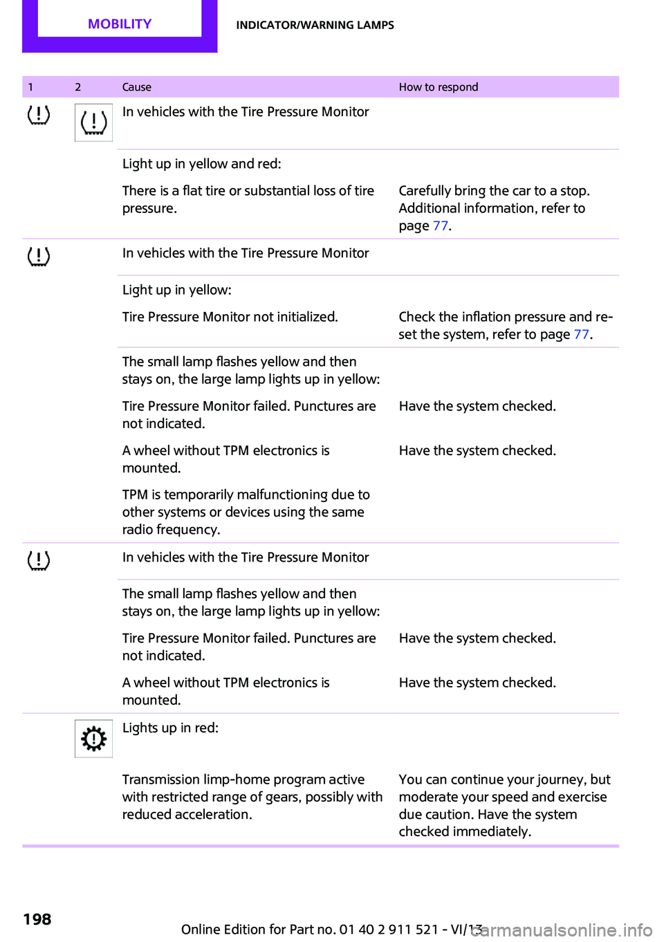
12CauseHow to respondIn vehicles with the Tire Pressure MonitorLight up in yellow and red:There is a flat tire or substantial loss of tire
pressure.Carefully bring the car to a stop.
Additional information, refer to
page 77.In vehicles with the Tire Pressure MonitorLight up in yellow:Tire Pressure Monitor not initialized.Check the inflation pressure and re‐
set the system, refer to page 77.The small lamp flashes yellow and then
stays on, the large lamp lights up in yellow:Tire Pressure Monitor failed. Punctures are
not indicated.Have the system checked.A wheel without TPM electronics is
mounted.Have the system checked.TPM is temporarily malfunctioning due to
other systems or devices using the same
radio frequency.In vehicles with the Tire Pressure MonitorThe small lamp flashes yellow and then
stays on, the large lamp lights up in yellow:Tire Pressure Monitor failed. Punctures are
not indicated.Have the system checked.A wheel without TPM electronics is
mounted.Have the system checked.Lights up in red:Transmission limp-home program active
with restricted range of gears, possibly with
reduced acceleration.You can continue your journey, but
moderate your speed and exercise
due caution. Have the system
checked immediately.Seite 198MobilityIndicator/warning lamps198
Online Edition for Part no. 01 40 2 911 521 - VI/13
Page 205 of 218
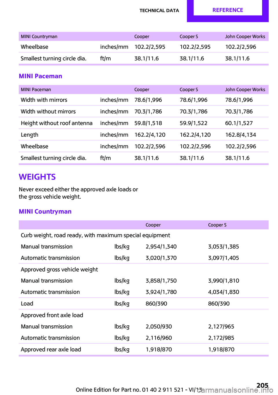
MINI CountrymanCooperCooper SJohn Cooper WorksWheelbaseinches/mm102.2/2,595102.2/2,595102.2/2,596Smallest turning circle dia.ft/m38.1/11.638.1/11.638.1/11.6
MINI Paceman
MINI PacemanCooperCooper SJohn Cooper WorksWidth with mirrorsinches/mm78.6/1,99678.6/1,99678.6/1,996Width without mirrorsinches/mm70.3/1,78670.3/1,78670.3/1,786Height without roof antennainches/mm59.8/1,51859.9/1,52260.1/1,527Lengthinches/mm162.2/4,120162.2/4,120162.8/4,134Wheelbaseinches/mm102.2/2,596102.2/2,596102.2/2,596Smallest turning circle dia.ft/m38.1/11.638.1/11.638.1/11.6Weights
Never exceed either the approved axle loads or
the gross vehicle weight.MINI Countryman
CooperCooper SCurb weight, road ready, with maximum special equipmentManual transmissionlbs/kg2,954/1,3403,053/1,385Automatic transmissionlbs/kg3,020/1,3703,097/1,405Approved gross vehicle weightManual transmissionlbs/kg3,858/1,7503,990/1,810Automatic transmissionlbs/kg3,924/1,7804,034/1,830Loadlbs/kg860/390860/390Approved front axle loadManual transmissionlbs/kg2,050/9302,127/965Automatic transmissionlbs/kg2,116/9602,172/985Approved rear axle loadlbs/kg1,918/8701,918/870Seite 205Technical dataReference205
Online Edition for Part no. 01 40 2 911 521 - VI/13
Page 208 of 218
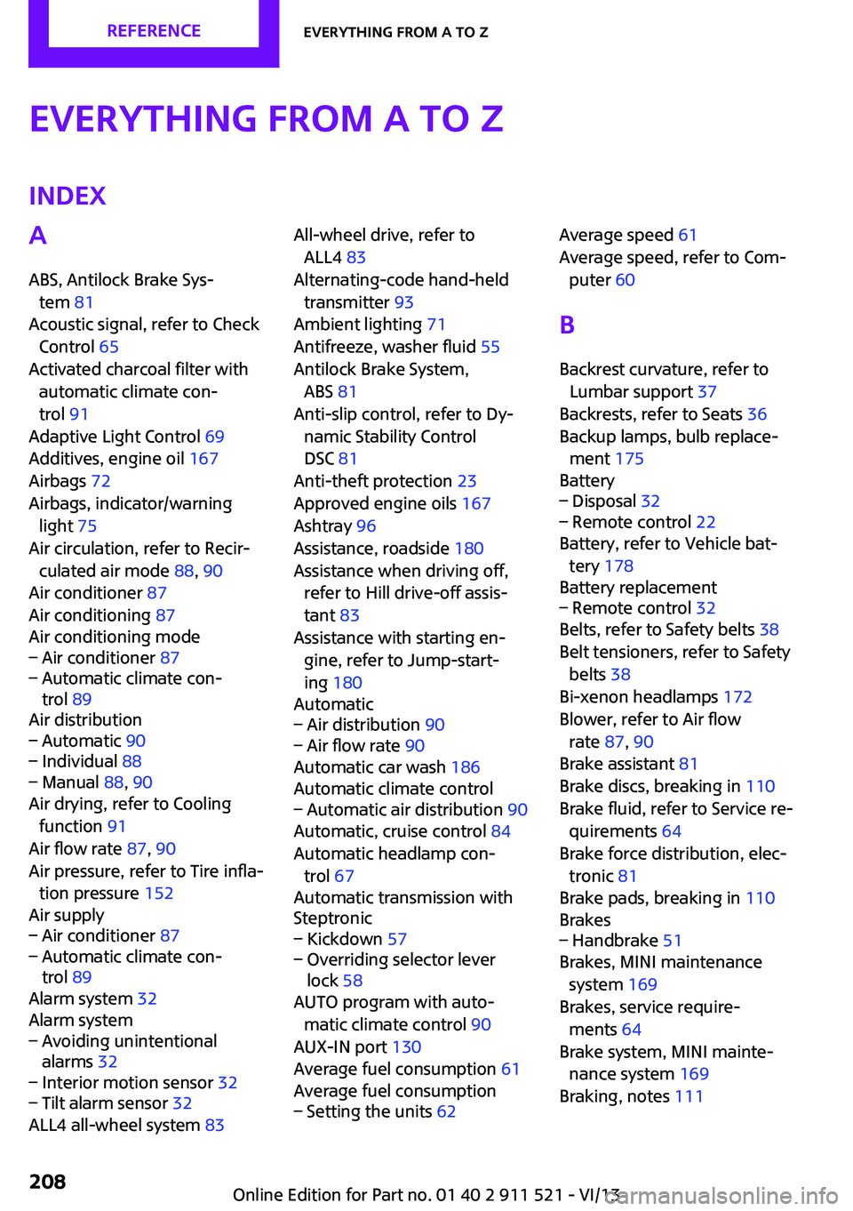
Everything from A to ZIndexA
ABS, Antilock Brake Sys‐ tem 81
Acoustic signal, refer to Check Control 65
Activated charcoal filter with automatic climate con‐
trol 91
Adaptive Light Control 69
Additives, engine oil 167
Airbags 72
Airbags, indicator/warning light 75
Air circulation, refer to Recir‐ culated air mode 88, 90
Air conditioner 87
Air conditioning 87
Air conditioning mode– Air conditioner 87– Automatic climate con‐
trol 89
Air distribution
– Automatic 90– Individual 88– Manual 88, 90
Air drying, refer to Cooling
function 91
Air flow rate 87, 90
Air pressure, refer to Tire infla‐ tion pressure 152
Air supply
– Air conditioner 87– Automatic climate con‐
trol 89
Alarm system 32
Alarm system
– Avoiding unintentional
alarms 32– Interior motion sensor 32– Tilt alarm sensor 32
ALL4 all-wheel system 83
All-wheel drive, refer to
ALL4 83
Alternating-code hand-held transmitter 93
Ambient lighting 71
Antifreeze, washer fluid 55
Antilock Brake System, ABS 81
Anti-slip control, refer to Dy‐ namic Stability Control
DSC 81
Anti-theft protection 23
Approved engine oils 167
Ashtray 96
Assistance, roadside 180
Assistance when driving off, refer to Hill drive-off assis‐
tant 83
Assistance with starting en‐ gine, refer to Jump-start‐
ing 180
Automatic– Air distribution 90– Air flow rate 90
Automatic car wash 186
Automatic climate control
– Automatic air distribution 90
Automatic, cruise control 84
Automatic headlamp con‐ trol 67
Automatic transmission with
Steptronic
– Kickdown 57– Overriding selector lever
lock 58
AUTO program with auto‐
matic climate control 90
AUX-IN port 130
Average fuel consumption 61
Average fuel consumption
– Setting the units 62Average speed 61
Average speed, refer to Com‐ puter 60
B Backrest curvature, refer to Lumbar support 37
Backrests, refer to Seats 36
Backup lamps, bulb replace‐ ment 175
Battery– Disposal 32– Remote control 22
Battery, refer to Vehicle bat‐
tery 178
Battery replacement
– Remote control 32
Belts, refer to Safety belts 38
Belt tensioners, refer to Safety belts 38
Bi-xenon headlamps 172
Blower, refer to Air flow rate 87, 90
Brake assistant 81
Brake discs, breaking in 110
Brake fluid, refer to Service re‐ quirements 64
Brake force distribution, elec‐ tronic 81
Brake pads, breaking in 110
Brakes
– Handbrake 51
Brakes, MINI maintenance
system 169
Brakes, service require‐ ments 64
Brake system, MINI mainte‐ nance system 169
Braking, notes 111
Seite 208ReferenceEverything from A to Z208
Online Edition for Part no. 01 40 2 911 521 - VI/13