ECO mode MINI Coupe 2014 Owner's Manual (Mini Connected)
[x] Cancel search | Manufacturer: MINI, Model Year: 2014, Model line: Coupe, Model: MINI Coupe 2014Pages: 288, PDF Size: 6.72 MB
Page 8 of 288

your skin by washing thoroughly with soap and
water.
Service and warranty
We recommend that you read this publication
thoroughly. Your vehicle is covered by the fol‐
lowing warranties:▷New Vehicle Limited Warranty.▷Rust Perforation Limited Warranty.▷Federal Emissions System Defect Warranty.▷Federal Emissions Performance Warranty.▷California Emission Control System Limited
Warranty.
Detailed information about these warranties is
listed in the Service and Warranty Information
Booklet for US models or in the Warranty and
Service Guide Booklet for Canadian models.
Your vehicle has been specifically adapted and
designed to meet the particular operating con‐
ditions and homologation requirements in your
country and continental region in order to de‐
liver the full driving pleasure while the vehicle is
operated under those conditions. If you wish to
operate your vehicle in another country or re‐
gion, you may be required to adapt your vehi‐
cle to meet different prevailing operating con‐
ditions and homologation requirements. You
should also be aware of any applicable war‐
ranty limitations or exclusions for such country
or region. In such case, please contact Cus‐
tomer Relations for further information.
Maintenance
Maintain the vehicle regularly to sustain the
road safety, operational reliability and the New
Vehicle Limited Warranty.
Specifications for required maintenance meas‐
ures:
▷MINI Maintenance system▷Service and Warranty Information Booklet
for US models▷Warranty and Service Guide Booklet for
Canadian modelsIf the vehicle is not maintained according to
these specifications, this could result in serious
damage to the vehicle. Such damage is not
covered by the MINI New Vehicle Limited War‐
ranty.
Data memory
Numerous electronic components in your vehi‐
cle contain data memories that store technical
information on the vehicle condition, events and faults, either temporarily or permanently.This technical information generally documents
the state of a component, a module, a system
or the environment.▷Operating conditions of system compo‐
nents, such as filling levels.▷Status messages from the vehicle and its in‐
dividual components, such as wheel rpm/
speed, motion delay, transverse accelera‐
tion.▷Malfunctions and defects in important sys‐
tem components, such as lights and brakes.▷Vehicle responses to special driving situa‐
tions, such as airbag deployment, use of
the stability control systems.▷Ambient conditions, such as the tempera‐
ture.
These data are of a technical nature only and
are used to detect and eliminate faults and to
optimize vehicle functions. Travel profiles of
routes driven with the vehicle cannot be cre‐
ated from these data. If services are used, for
instance in the event of repairs, service proc‐
esses, warranty cases, quality assurance, etc.,
this technical information can be read out from
the event and fault data memories by service
personnel, including the manufacturer, using
special diagnosis tools. This service personnel
can provide you with more information if
needed. After troubleshooting, the information
in the fault memory is cleared or overwritten
continuously.
Seite 8Notes8
Online Edition for Part no. 01 40 2 911 498 - VI/13
Page 14 of 288

CockpitVehicle equipment
This chapter describes all series equipment as
well as country-specific and special equipment
offered for this model series.Therefore, it alsodescribes equipment that may not be found in
your vehicle, for instance due to the selected
special equipment or the country version. This
also applies to safety-related functions and sys‐
tems.
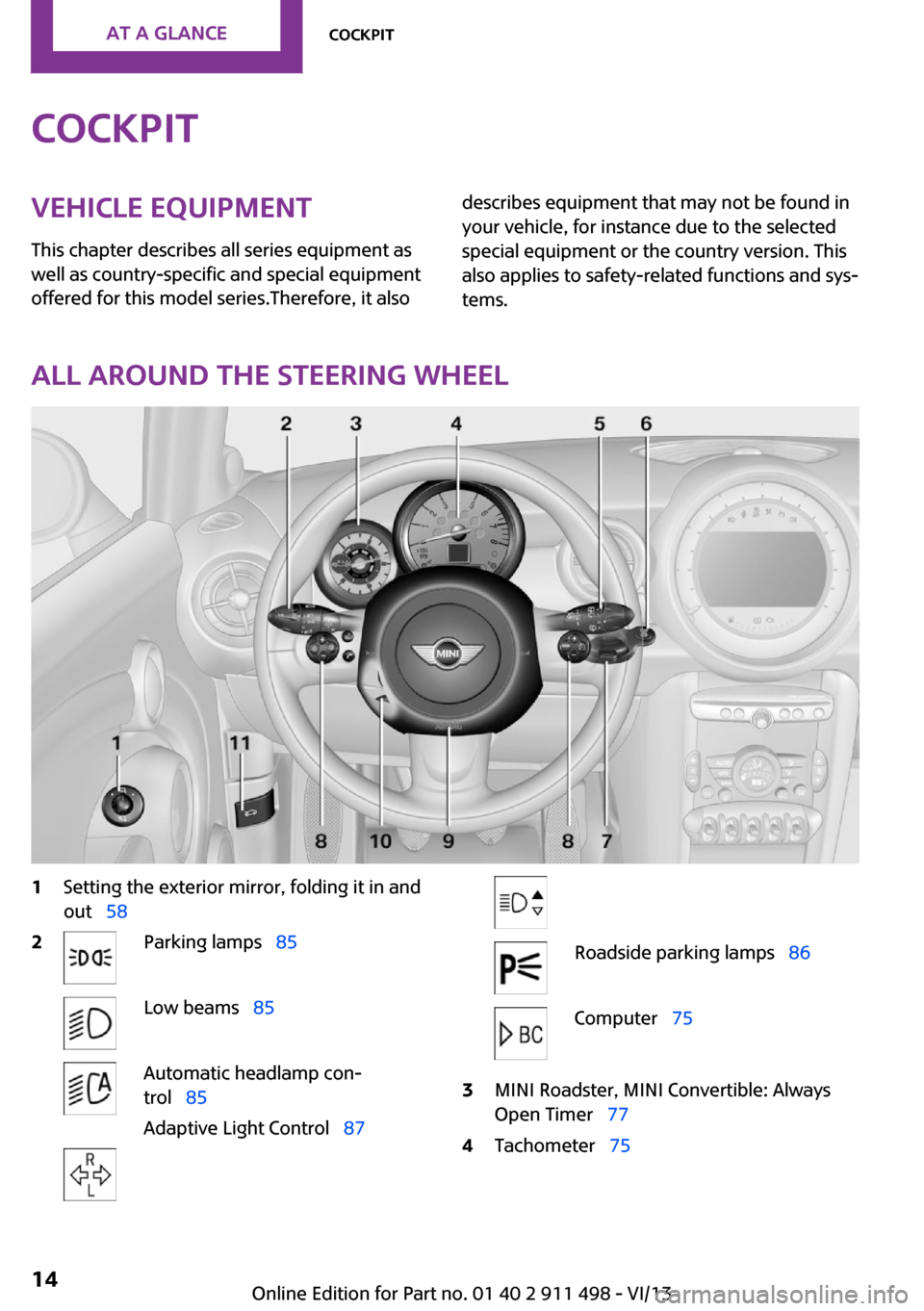
All around the steering wheel
1Setting the exterior mirror, folding it in and
out 582Parking lamps 85Low beams 85Automatic headlamp con‐
trol 85
Adaptive Light Control 87Roadside parking lamps 86Computer 753MINI Roadster, MINI Convertible: Always
Open Timer 774Tachometer 75Seite 14At a glanceCockpit14
Online Edition for Part no. 01 40 2 911 498 - VI/13
Page 20 of 288

Onboard monitorVehicle equipmentThis chapter describes all series equipment as
well as country-specific and special equipment
offered for this model series.Therefore, it also
describes equipment that may not be found in
your vehicle, for instance due to the selected
special equipment or the country version. This
also applies to safety-related functions and sys‐
tems.
The concept The onboard monitor combines the functions
of a large number of different switches. Thus,
these functions can be operated from a central
location.
Using the onboard monitor during a trip
To avoid becoming distracted and posing
an unnecessary hazard to your vehicle's occu‐
pants and to other road users, never attempt to
use the controls or enter information unless
traffic and road conditions allow this. ◀
Controls at a glance Controls1Control Display2MINI joystick with buttonsThe buttons can be used to open the me‐
nus directly. The MINI joystick can be used
to select menu items and create settings.
Control Display
Notes
▷To clean the Control Display, follow the care
instructions, refer to page 263.▷Do not place objects close to the Control
Display; otherwise, the Control Display can
be damaged.
Switching off
1.Move the MINI joystick repeatedly to the
right until the "Options" menu appears.2."Switch off control display"
Switching on
Press the MINI joystick to switch on.
Seite 20At a glanceOnboard monitor20
Online Edition for Part no. 01 40 2 911 498 - VI/13
Page 71 of 288

All washer nozzles are supplied from one reser‐
voir.
The recommended minimum filling quantity is
0.2 US gal/1 liter.
Fill with a mixture of window washing concen‐
trate and water; if needed, add antifreeze ac‐
cording to the manufacturer instructions.
Mix the washer fluid before adding to maintain
the correct mixing ratio.
Do not fill in undiluted window washing con‐
centrate and do not fill in pure water; this could
damage the washer system.
Do not mix window washing concentrate from
different manufacturers; this could cause the
washer nozzles to clog.
Manual transmission
Pay attention to the shift plane
When shifting into 5th or 6th gear, push
the gearshift lever to the right; otherwise inad‐
vertent shifting into the 3rd or 4th gear could
lead to engine damage. ◀
Reverse gear
Select only when the vehicle is stationary. When
the gearshift lever is pressed to the left, a slight
resistance needs to be overcome.
Automatic transmission
with Steptronic
In addition to the fully automatic mode, gears
can also be shifted manually using Steptronic,
refer to page 72.
Parking the vehicle Secure the vehicle
Before leaving the vehicle with the en‐
gine running, move the selector lever to posi‐
tion P and set the handbrake; otherwise, the
vehicle will begin moving. ◀
Disengaging the remote control
To remove the remote control from the ignition
lock, first move the selector lever to position P
and switch off the engine: interlock. Remove
the remote control from the ignition lock, refer
to page 65.
Selector lever positions
P R N D M/S + –
Displays in the tachometer
The selector lever position is displayed and the
engaged gear, such as M4, is displayed in
manual mode.
Seite 71DrivingControls71
Online Edition for Part no. 01 40 2 911 498 - VI/13
Page 72 of 288

Changing selector lever positions▷With the ignition switched on or the engine
running, the selector lever can be moved
out of position P.▷When the vehicle is stationary, step on the
brake before shifting out of P or N; other‐
wise, the selector lever is locked: shiftlock.
Press on the brake pedal until you
start driving
To prevent the vehicle from creeping after
you select a driving position, maintain pres‐
sure on the brake pedal until you are ready
to start. ◀
A lock prevents accidental shifting into selector
lever positions R and P.
To override the lock, press the button on the
front of the selector lever, see arrow.
P Park
Select only when the vehicle is stationary. The
front wheels are blocked.
R is Reverse
Select only when the vehicle is stationary.
N is NeutralFor example, engage this position in a car
wash. The vehicle can roll.
D Drive, automatic position Position for normal vehicle operation. All for‐
ward gears are selected automatically.
Under normal operating conditions, fuel con‐
sumption is lowest when you are driving in po‐
sition D.
Kickdown
Kickdown is used to achieve maximum driving
performance. Press on the accelerator beyond
the resistance point at the full throttle position.
Sport program and manual mode M/S
Activating the Sport program
Move the selector lever from position D toward
the left into the M/S shifting slot.
The Sport program is activated and DS is dis‐
played. This position is recommended for a per‐
formance-oriented driving style.
To deactivate the Sport program or manual
mode M/S, move the selector lever to the right
into position D.
Activating the M/S manual mode Move the selector lever from position D towardthe left into the M/S shifting slot.
Push the selector lever forward or backward.
Manual mode becomes active and the gear is
changed.
The tachometer displays the engaged gear,
e. g. M1.
▷To shift up: press the selector lever back‐
ward.▷To shift down: press the selector lever for‐
ward.Seite 72ControlsDriving72
Online Edition for Part no. 01 40 2 911 498 - VI/13
Page 85 of 288

LampsVehicle equipmentThis chapter describes all series equipment as
well as country-specific and special equipment
offered for this model series.Therefore, it also
describes equipment that may not be found in
your vehicle, for instance due to the selected
special equipment or the country version. This
also applies to safety-related functions and sys‐
tems.
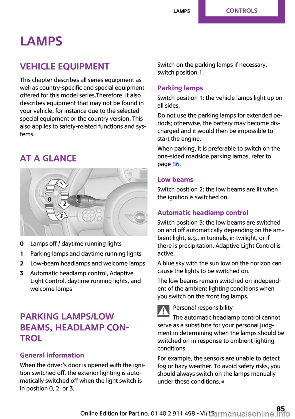
At a glance0Lamps off / daytime running lights1Parking lamps and daytime running lights2Low-beam headlamps and welcome lamps3Automatic headlamp control, Adaptive
Light Control, daytime running lights, and
welcome lamps
Parking lamps/low
beams, headlamp con‐
trol
General information
When the driver's door is opened with the igni‐
tion switched off, the exterior lighting is auto‐
matically switched off when the light switch is
in position 0, 2, or 3.
Switch on the parking lamps if necessary,
switch position 1.
Parking lamps Switch position 1: the vehicle lamps light up on
all sides.
Do not use the parking lamps for extended pe‐
riods; otherwise, the battery may become dis‐
charged and it would then be impossible to
start the engine.
When parking, it is preferable to switch on the
one-sided roadside parking lamps, refer to
page 86.
Low beams Switch position 2: the low beams are lit when
the ignition is switched on.
Automatic headlamp control Switch position 3: the low beams are switched
on and off automatically depending on the am‐
bient light, e.g., in tunnels, in twilight, or if
there is precipitation. Adaptive Light Control is
active.
A blue sky with the sun low on the horizon can
cause the lights to be switched on.
The low beams remain switched on independ‐
ent of the ambient lighting conditions when
you switch on the front fog lamps.
Personal responsibility
The automatic headlamp control cannot
serve as a substitute for your personal judg‐
ment in determining when the lamps should be
switched on in response to ambient lighting
conditions.
For example, the sensors are unable to detect
fog or hazy weather. To avoid safety risks, you
should always switch on the lamps manually
under these conditions. ◀Seite 85LampsControls85
Online Edition for Part no. 01 40 2 911 498 - VI/13
Page 98 of 288

For a vehicle containing an average load, the
possible driving distance is ap‐
prox. 50 miles/80 km.
When the vehicle is driven with a damaged tire,
its handling characteristics change, e.g., re‐
duced lane stability during braking, a longer
braking distance, and altered self-steering
properties. Adjust your driving style accord‐
ingly. Avoid abrupt steering maneuvers or driv‐
ing over obstacles, e. g., curbs, potholes, etc.
Because the possible driving distance depends
on how the vehicle is used during the trip, the
actual distance may be smaller or greater de‐
pending on the driving speed, road conditions,
external temperature, cargo load, etc.
Continued driving with a flat tire
Drive moderately and do not exceed a
speed of 50 mph/80 km/h.
A loss of tire inflation pressure results in a
change in the handling characteristics, e.g., re‐
duced lane stability during braking, a longer
braking distance and altered self-steering prop‐
erties. ◀
Final tire failure
Vibrations or loud noises while driving
can indicate the final failure of the tire. Reduce
speed and stop; otherwise, pieces of the tire
could come loose and cause an accident. Do
not continue driving, and contact your service
center. ◀
Message when not reset The yellow warning lamp lights up. A
message is displayed on the onboard
monitor.
The system detected a wheel change but was
not yet reset. Warnings regarding the current
tire inflation pressure are not reliable.
Check the tire inflation pressure and reset the
system, refer to page 96.Malfunction
The small warning lamp flashes in yel‐
low and then lights up continuously; the
larger warning lamp comes on in yel‐
low.
On the onboard monitor, the tires are shown in
gray and a message appears.
No flat tire can be detected.
Display in the following situations:▷A wheel without TPM electronics is
mounted:
Have the system checked by the service
center if necessary.▷Malfunction:
Have the system checked.▷TPM could not be fully reset; reset the sys‐
tem again.
The small warning lamp flashes in yel‐
low and then lights up continuously; the
larger warning lamp comes on in yel‐
low.
On the onboard monitor, the tires are shown in
gray and a message appears.
No flat tire can be detected.
Display in the following situation:
▷Disturbance by other systems or devices
with the same radio frequency
After leaving the area of the disturbance,
the system automatically becomes active
again.
Declaration according to NHTSA/FMVSS
138 Tire Pressure Monitoring Systems
Each tire, including the spare (if provided)
should be checked monthly when cold and in‐
flated to the inflation pressure recommended
by the vehicle manufacturer on the vehicle
placard or tire inflation pressure label (If your
vehicle has tires of a different size than the size indicated on the vehicle placard or tire inflation
Seite 98ControlsSafety98
Online Edition for Part no. 01 40 2 911 498 - VI/13
Page 101 of 288

Driving stability control systemsVehicle equipment
This chapter describes all series equipment as
well as country-specific and special equipment
offered for this model series.Therefore, it also
describes equipment that may not be found in
your vehicle, for instance due to the selected
special equipment or the country version. This
also applies to safety-related functions and sys‐
tems.
Antilock Brake System
ABS
ABS prevents locking of the wheels duringbraking.
Steerability is maintained even during full brak‐
ing. This increases active driving safety.
ABS is operational every time you start the en‐
gine.
Electronic brake-force distribution EBVThe system controls the brake pressure in the
rear wheels to ensure stable braking behavior.
CBC Cornering Brake Control
When braking in curves or during a lane
change, driving stability and steering response
are improved further.
Brake assistant When the brakes are applied rapidly, this sys‐
tem automatically produces the maximum
braking force boost. In this way, the system
helps keep the braking distance as short as
possible. This system utilizes all of the benefits
provided by ABS.Do not reduce the pressure on the brake pedal
for the duration of full braking.
Dynamic Stability Con‐
trol DSC
The concept
DSC prevents traction loss in the driving wheels
when driving away and accelerating.
DSC also recognizes unstable vehicle condi‐
tions, such as fishtailing or nose-diving. Subject
to physical limits, DSC helps to keep the vehicle
on a steady course by reducing engine speed
and by applying brakes to the individual
wheels.
DSC is operational every time you start the en‐
gine.
Adjust your driving style to the situation
An appropriate driving style is always the
responsibility of the driver.
The laws of physics cannot be repealed, even
with DSC.
Do not reduce the additional safety margin
with a risky driving style, as otherwise there is a
risk of an accident. ◀
Deactivating DSCSeite 101Driving stability control systemsControls101
Online Edition for Part no. 01 40 2 911 498 - VI/13
Page 109 of 288

Cooling functionThe passenger compartment can
only be cooled with the engine
running.
The cooling function cools and
dehumidifies the incoming air
before reheating it as required, according to
the temperature setting.
The cooling function helps to prevent conden‐
sation on the windows or to remove it quickly.
Depending on the weather, the windshield may
fog up briefly when the engine is started.
To cool the air faster and more intensively
when external temperatures are high, switch
on the recirculated air mode.
Recirculated air mode If the air outside the car has an
unpleasant odor or contains pol‐
lutants, shut off the supply to the
interior of the car temporarily.
The system then recirculates the
air currently within the vehicle.
Should the windows fog up in the recirculated-
air mode, press the AUTO button or switch off
the recirculated-air mode and increase the air
volume if necessary. Make sure that air can
flow onto the windshield.
Recirculated air mode is automatically deacti‐
vated at low external temperatures.
Only use recirculated air mode for a lim‐
ited period
The recirculated air mode should not be used
continuously for lengthy periods; otherwise, the
quality of the air inside the car will gradually
deteriorate. ◀Temperature
Turn upward, red, to raise thetemperature.
Turn downward, blue, to lower
the temperature.
Rear window defroster The rear window defroster
switches off automatically after a
certain period of time.
The rear window defroster
power may be lowered or even
switched off entirely to save on battery power.
Vent settings Direct the flow of air to the win‐
dows
, to the upper body
area
, or to the footwell .
Intermediate positions are possi‐
ble.
Windshield heating The windshield heating switches
off automatically after some
time.
The windshield heating may be
reduced or even switched off en‐
tirely to save on battery power.
Defrosting and defogging windows
1.Set the maximum air volume.2.Air distribution in position .
By switching on the cooling function, the
windows are defogged more rapidly.3.Set the highest temperature, red.4.Deactivate recirculated air mode.5.Switch on the windshield heating if neces‐
sary.6.Switch on the rear window defroster if nec‐
essary.Seite 109ClimateControls109
Online Edition for Part no. 01 40 2 911 498 - VI/13
Page 111 of 288

Air volume, manualPress the – button to reduce the
air volume. Press the + button to
increase the air volume.
The automatic mode for the air volume can be switched on
again using the AUTO button.
The air flow rate may be reduced or the blower
may be switched off entirely to save on battery
power. The display remains the same.
Switching the system on/off
Reduce the air volume by pressing the – button
until the system is switched off. All displays go
out.
Press the AUTO button to switch the automatic
climate control back on.
AUTO program The AUTO program automati‐
cally adjusts the air distribution
to the windshield and side win‐
dows, toward the upper body
area, and into the footwell. The
air volume and your specifications for the tem‐
perature are adjusted to outside influences due
to the seasons, e. g., solar radiation.
The cooling function is switched on automati‐
cally with the AUTO program.
The program is switched off if the air distribu‐
tion is manually adjusted or the button is
pressed again.
Convertible program When the convertible top is open, the
convertible program is activated. In the
convertible program, the automatic climate
control is optimized for driving with the
convertible top open. In addition, the air flow
rate is increased as vehicle speed increases.The effectiveness of the convertible program
can be enhanced considerably by installing the
wind deflector.
Recirculated air mode If the air outside the car has an
unpleasant odor or contains pol‐
lutants, shut off the supply to the
interior of the car temporarily.
The system then recirculates the
air currently within the vehicle.
Should the windows fog up in the recirculated-
air mode, press the AUTO button or switch off
the recirculated-air mode and increase the air
volume if necessary. Make sure that air can
flow onto the windshield.
Recirculated air mode is automatically deacti‐
vated at low external temperatures.
Only use recirculated air mode for a lim‐
ited period
The recirculated air mode should not be used continuously for lengthy periods; otherwise, the
quality of the air inside the car will gradually deteriorate. ◀
Maximum cooling Automatic climate control
switches to the lowest tempera‐
ture, a high air volume, and re‐
circulated air mode.
For maximum cooling, open the
vents for the upper body area.
The air is cooled as quickly as possible:▷At an external temperature above
32 ℉/0 ℃.▷When the engine is running.Seite 111ClimateControls111
Online Edition for Part no. 01 40 2 911 498 - VI/13