service MINI COUPE ROADSTER CONVERTIBLE 2012 Owners Manual
[x] Cancel search | Manufacturer: MINI, Model Year: 2012, Model line: COUPE ROADSTER CONVERTIBLE, Model: MINI COUPE ROADSTER CONVERTIBLE 2012Pages: 283, PDF Size: 9.38 MB
Page 7 of 283
Notes
6
Service and warranty
We recommend that you read this publication
thoroughly.
Your MINI is covered by the following
warranties:
> New Vehicle Limited Warranty
> Rust Perforation Limited Warranty
> Federal Emissions Syst em Defect Warranty
> Federal Emissions Performance Warranty
> California Emission Control System Limited
Warranty
Detailed information about these warranties is
listed in the Service and Warranty Information
Booklet for US models or in the Warranty and
Service Guide Booklet for Canadian models.
Your vehicle has been specifically adapted and
designed to meet the pa rticular operating con-
ditions and registration requirements in your
country and continental region in order to
deliver the full driving pleasure while the vehicle
is operated under those conditions. If you wish
to operate your vehicle in another country or
region, you may be requ ired to adapt your
vehicle to meet different prevailing operating
conditions and registration requirements. You
should also be aware of any applicable warranty
limitations or exclusions for such country or
region. In such a case, please contact Customer
Relations for further information.
Maintenance
Maintain the vehicle regularly to sustain road
safety, operational reliability and the New
Vehicle Limited Warranty.
Specifications for required maintenance
measures:
> MINI Maintenance System
> Service and Warranty Information Booklet
for US models
> Warranty and Service Guide Booklet for
Canadian models If the vehicle is not ma
intained according to
these specifications, this could result in serious
damage to the vehicle. Such damage is not cov-
ered by the MINI New Vehicle Limited Warranty.
Reporting safety defects
For US customers
The following applies only to vehicles owned
and operated in the US.
If you believe that your vehicle has a defect that
could cause a crash or could cause injury or
death, you should immediately inform the
National Highway Traffic Safety Administration,
NHTSA, in addition to notifying MINI of North
America, LLC, P.O. Box 1227, Westwood, New
Jersey 07675-1227, Telephone 1-800-831-
1117.
If NHTSA receives similar complaints, it may
open an investigation, and if it finds that a safety
defect exists in a group of vehicles, it may order
a recall and remedy ca mpaign. However, NHTSA
cannot become involved in individual problems
between you, your dealer, or MINI of North
America, LLC.
To contact NHTSA, you may call the Vehicle
Safety Hotline toll-free at 1-888-327-4236 (TTY:
1-800-424-9153); go to http://www.safer-
car.gov; or write to: Ad ministrator, NHTSA, 400
Seventh Street, SW., Washington, DC 20590. You
can also obtain other information about motor
vehicle safety from http://www.safercar.gov
For Canadian customers
Canadian customers who wish to report a
safety-related defect to Transport Canada,
Defect Investigations and Recalls, may tele-
phone the toll-free hotline 1-800-333-0510.
You can also obtain ot her information about
motor vehicle safety from http://www.tc.gc.ca/
roadsafety
00320051004F004C00510048000300280047004C0057004C005200510003
Page 13 of 283
AT A GLANCECockpit
12
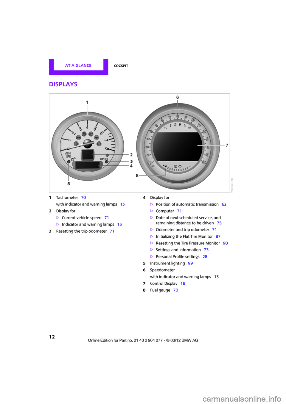
Displays
1Tachometer 70
with indicator and warning lamps 13
2 Display for
>Current vehicle speed 71
> Indicator and warning lamps 13
3 Resetting the trip odometer 714
Display for
>Position of automatic transmission 62
> Computer 71
> Date of next scheduled service, and
remaining distance to be driven 75
> Odometer and trip odometer 71
> Initializing the Flat Tire Monitor 87
> Resetting the Tire Pressure Monitor 90
> Settings and information 73
> Personal Prof ile settings28
5 Instrument lighting 99
6 Speedometer
with indicator and warning lamps 13
7 Control Display 18
8 Fuel gauge 70
00320051004F004C00510048000300280047004C0057004C005200510003
Page 29 of 283
CONTROLSOpening and closing
28
Opening and closing
Vehicle equipment
In this chapter, all production, country, and
optional equipment that is offered in the model
range is described. Equipment is also described
that is not available because of, for example,
selected options or coun try version. This also
applies to safety relate d functions and systems.
Keys/remote controls
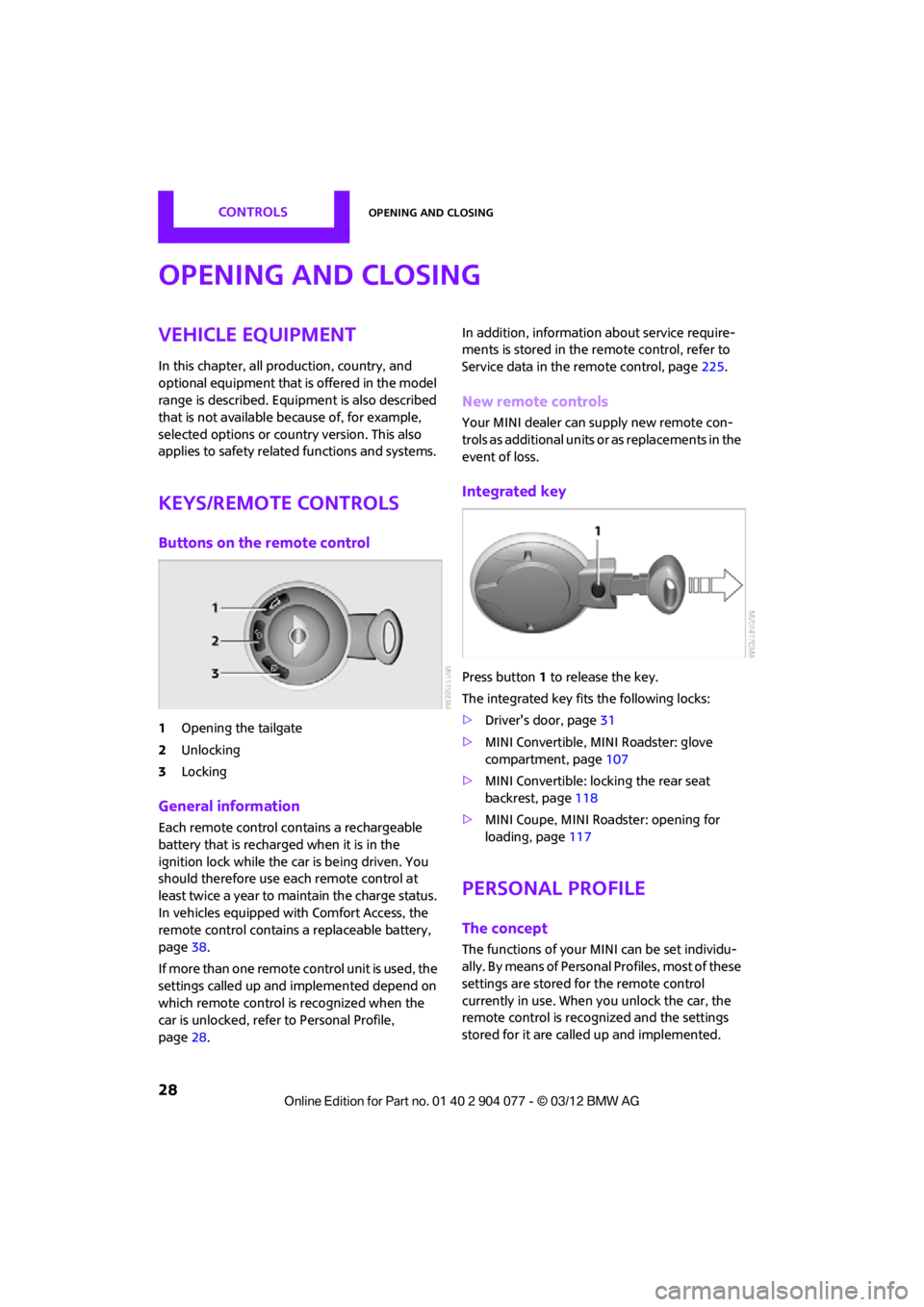
Buttons on the remote control
1Opening the tailgate
2 Unlocking
3 Locking
General information
Each remote control co ntains a rechargeable
battery that is recharged when it is in the
ignition lock while the car is being driven. You
should therefore use each remote control at
least twice a year to maintain the charge status.
In vehicles equipped with Comfort Access, the
remote control contains a replaceable battery,
page 38.
If more than one remote control unit is used, the
settings called up and implemented depend on
which remote control is recognized when the
car is unlocked, refer to Personal Profile,
page 28. In addition, information about service require-
ments is stored in the remote control, refer to
Service data in the remote control, page
225.
New remote controls
Your MINI dealer can supply new remote con-
trols as additional units or as replacements in the
event of loss.
Integrated key
Press button1 to release the key.
The integrated key fits the following locks:
> Driver's door, page 31
> MINI Convertible, MINI Roadster: glove
compartment, page 107
> MINI Convertible: locking the rear seat
backrest, page 118
> MINI Coupe, MINI Roadster: opening for
loading, page 117
Personal Profile
The concept
The functions of your MINI can be set individu-
ally. By means of Personal Profiles, most of these
settings are stored fo r the remote control
currently in use. When you unlock the car, the
remote control is recognized and the settings
stored for it are called up and implemented.
00320051004F004C00510048000300280047004C0057004C005200510003
Page 76 of 283
Controls overviewCONTROLS
75
Service requirements
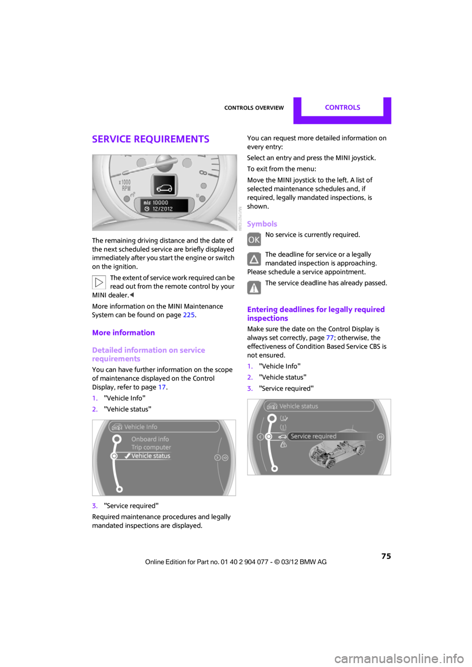
The remaining driving distance and the date of
the next scheduled service are briefly displayed
immediately after you start the engine or switch
on the ignition.
The extent of service work required can be
read out from the remo te control by your
MINI dealer. <
More information on the MINI Maintenance
System can be found on page 225.
More information
Detailed information on service
requirements
You can have further information on the scope
of maintenance displayed on the Control
Display, refer to page17.
1. "Vehicle Info"
2. "Vehicle status"
3. "Service required"
Required maintenance procedures and legally
mandated inspections are displayed. You can request more de
tailed information on
every entry:
Select an entry and press the MINI joystick.
To exit from the menu:
Move the MINI joystick to the left. A list of
selected maintenance schedules and, if
required, legally mandated inspections, is
shown.
Symbols
No service is currently required.
The deadline for service or a legally
mandated inspection is approaching.
Please schedule a service appointment.
The service deadline has already passed.
Entering deadlines for legally required
inspections
Make sure the date on the Control Display is
always set correctly, page 77; otherwise, the
effectiveness of Condition Based Service CBS is
not ensured.
1. "Vehicle Info"
2. "Vehicle status"
3. "Service required"
00320051004F004C00510048000300280047004C0057004C005200510003
Page 94 of 283
Technology for driving comfort and safetyCONTROLS
93
Airbags
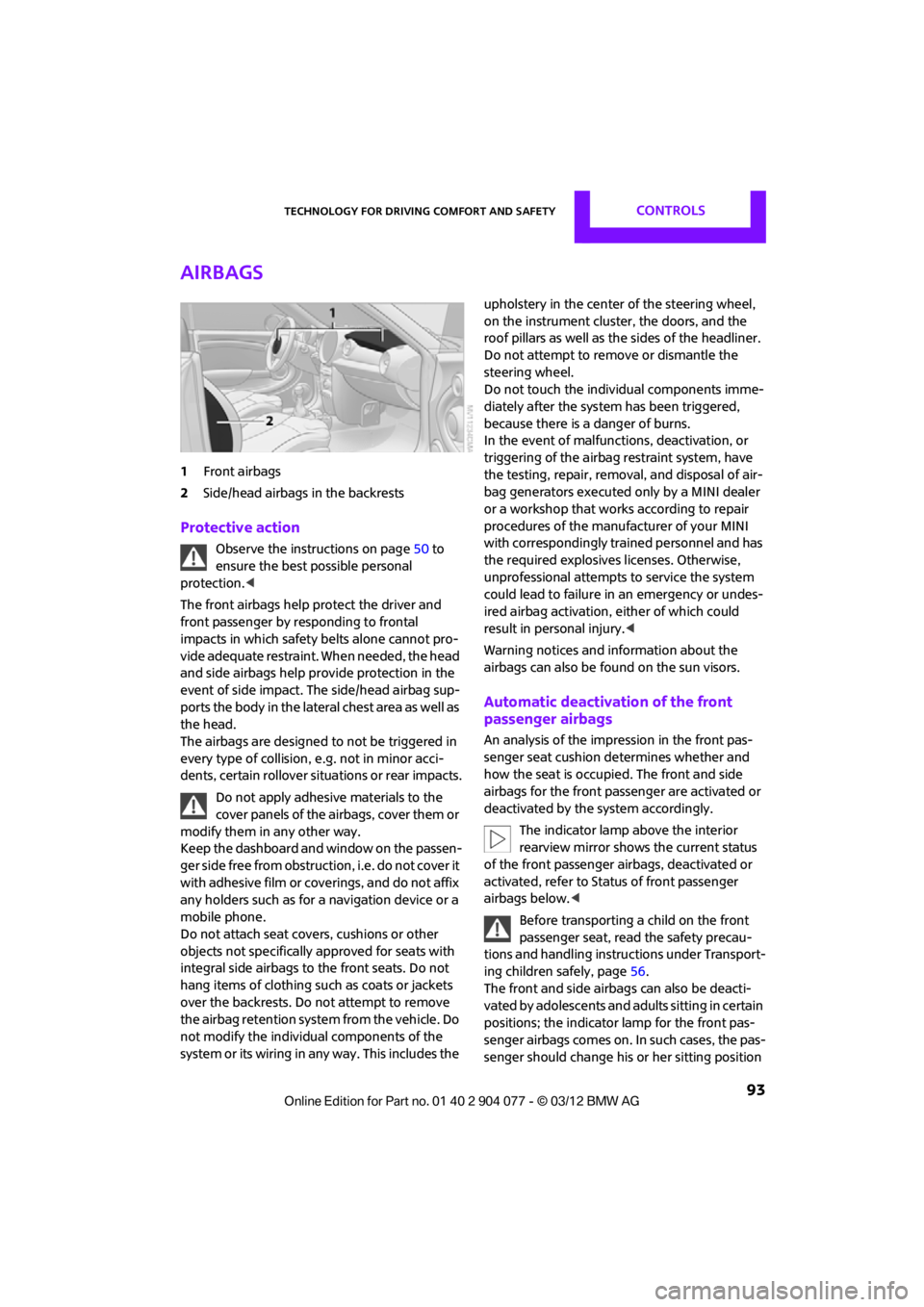
1Front airbags
2 Side/head airbags in the backrests
Protective action
Observe the instructions on page 50 to
ensure the best possible personal
protection.<
The front airbags help protect the driver and
front passenger by responding to frontal
impacts in which safety belts alone cannot pro-
vide adequate restraint. When needed, the head
and side airbags help provide protection in the
event of side impact. The side/head airbag sup-
ports the body in the lateral chest area as well as
the head.
The airbags are designed to not be triggered in
every type of collision, e.g. not in minor acci-
dents, certain rollover si tuations or rear impacts.
Do not apply adhesive materials to the
cover panels of the airbags, cover them or
modify them in any other way.
Keep the dashboard and window on the passen-
g e r s i d e f r e e f r o m o b s t r u c t i o n , i . e . d o n o t c o v e r i t
with adhesive film or coverings, and do not affix
any holders such as for a navigation device or a
mobile phone.
Do not attach seat covers, cushions or other
objects not specifically approved for seats with
integral side airbags to the front seats. Do not
hang items of clothing such as coats or jackets
over the backrests. Do not attempt to remove
the airbag retention system from the vehicle. Do
not modify the individual components of the
system or its wiring in any way. This includes the upholstery in the center of the steering wheel,
on the instrument cluster, the doors, and the
roof pillars as well as the sides of the headliner.
Do not attempt to remove or dismantle the
steering wheel.
Do not touch the individual components imme-
diately after the system has been triggered,
because there is a danger of burns.
In the event of malfuncti
ons, deactivation, or
triggering of the airbag restraint system, have
the testing, repair, remova l, and disposal of air-
bag generators executed only by a MINI dealer
or a workshop that work s according to repair
procedures of the manufacturer of your MINI
with correspondingly trained personnel and has
the required explosives licenses. Otherwise,
unprofessional attempts to service the system
could lead to failure in an emergency or undes-
ired airbag activation, either of which could
result in personal injury.<
Warning notices and in formation about the
airbags can also be found on the sun visors.
Automatic deactivation of the front
passenger airbags
An analysis of the impression in the front pas-
senger seat cushion determines whether and
how the seat is occupied. The front and side
airbags for the front passenger are activated or
deactivated by the system accordingly.
The indicator lamp above the interior
rearview mirror shows the current status
of the front passenger airbags, deactivated or
activated, refer to Status of front passenger
airbags below. <
Before transporting a child on the front
passenger seat, read the safety precau-
tions and handling instructions under Transport-
ing children safely, page 56.
The front and side airbag s can also be deacti-
vated by adolescents and adults sitting in certain
positions; the indicator lamp for the front pas-
senger airbags comes on. In such cases, the pas-
senger should change his or her sitting position
00320051004F004C00510048000300280047004C0057004C005200510003
Page 96 of 283

Technology for driving comfort and safetyCONTROLS
95
MINI Convertible:
Rollover protection
system
The rollover protection system is automatically
activated in the event of a sufficiently severe
accident or with an extreme inclination in the
longitudinal axis. The ro ll bar located behind the
rear seat headrest is pr ojected within a fraction
of a second.
In addition to the reinforced windshield frame,
the rollover protection system increases the
safety for the vehicle occupants.
Never block the travel path of the rollover
protection system with any objects.
Always wear your safety belt, it protects you in a
minor car accident and, depending on the
severity of the accident, the safety belt tensioner
and the multilevel airbag system will protect
you. <
Lowering
If the rollover protection system releases
accidentally, have your MINI dealer check it.
If the rollover protective system is
extended, do not operate the convertible
top.
Never attempt to modify the individual compo-
nents or the electrical wiring of the rollover
protective system.
Have the necessary work on the rollover protec-
tion system of your MINI only carried out by an
authorized MINI dealer.
Faulty repair may lead to the failure of the
system or malfunctions.
Check the system regularly and in order to
ensure a long service life of all functions, it is
mandatory to ma intain the service intervals,
refer to page 75.<
00320051004F004C00510048000300280047004C0057004C005200510003
Page 106 of 283
ClimateCONTROLS
105
Temperature
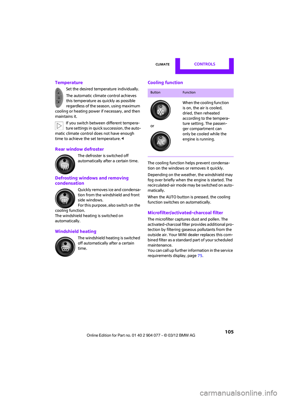
Set the desired temperature individually.
The automatic climate control achieves
this temperature as quickly as possible
regardless of the season, using maximum
cooling or heating power if necessary, and then
maintains it.
If you switch between different tempera-
ture settings in quic k succession, the auto-
matic climate control do es not have enough
time to achieve the set temperature. <
Rear window defroster
The defroster is switched off
automatically after a certain time.
Defrosting windows and removing
condensation
Quickly removes ice and condensa-
tion from the windshield and front
side windows.
For this purpose, also switch on the
cooling function.
The windshield heatin g is switched on
automatically.
Windshield heating
The windshield heating is switched
off automatically after a certain
time.
Cooling function
The cooling function helps prevent condensa-
tion on the windows or removes it quickly.
Depending on the weather, the windshield may
fog over briefly when the engine is started. The
recirculated-air mode may be switched on auto-
matically.
When the AUTO button is pressed, the cooling
function switches on automatically.
Microfilter/activated-charcoal filter
The microfilter captures dust and pollen. The
activated-charcoal filter provides additional pro-
tection by filtering gase ous pollutants from the
outside air. Your MINI dealer replaces this com-
bined filter as a standard part of your scheduled
maintenance.
You can call up further information in the service
requirements display, page 75.
ButtonFunction
or When the cooling function
is on, the air is cooled,
dried, then reheated
according to the tempera-
ture setting. The passen-
ger compartment can
only be cooled while the
engine is running.
00320051004F004C00510048000300280047004C0057004C005200510003
Page 115 of 283
DRIVING TIPSThings to remember when driving
114
Things to remember when driving
Vehicle equipment
In this chapter, all production, country, and
optional equipment that is offered in the model
range is described. Equipment is also described
that is not available because of, for example,
selected options or coun try version. This also
applies to safety relate d functions and systems.
Break-in period
Moving parts need breaking-in time to adjust to
each other. Please follow the instructions below
in order to achieve the optimal service life and
economy of operation for your vehicle.
Engine and differential
Always obey all official speed limits.
Up to 1,200 miles/2,000 km
Drive at varying engine and road speeds, but do
not exceed the following:
> Gasoline engine
4,500 rpm or 100 mph/160 km/h
Avoid full-throttle operation and use of the
transmission's kickdown mode.
After driving 1,200 miles/2,000 km
Engine and vehicle speeds can be gradually
increased.
Tires
Due to technical factors associated with their
manufacture, tires do not achieve their full
traction potential until af ter an initial break-in
period. Therefore, drive cautiously during the
first 200 miles/300 km.
Brake system
Brakes require an initial break-in period of
approx. 300 miles/500 km to achieve optimized
contact and wear patterns between brake pads
and rotors. Drive cautiously during this break-in
period.
Clutch
The function of the clutch reaches its optimal
level only after a distan ce driven of approx.
300 miles/500 km. During this break-in period,
engage the clutch gently.
Following part replacement
The same break-in procedures should be
observed if any of the components mentioned
above have to be renewed in the course of the
vehicle's operating life.
General driving notes
Close the tailgate
Only drive with the t ailgate closed. Failure
to do so may endanger passengers or
other road users or may damage the vehicle in
the event of an accident or a braking and eva-
sive maneuver. In addi tion, exhaust gas may
flow into the passenger compartment. <
If special circumstances make it absolutely
necessary to drive with the tailgate open:
1. Coupe: close all windows.
2. Switch off the recirculated-air mode and
switch the airflow contro l of the heating, air
conditioner, or automa tic climate control to
high, refer to page 102 or104.
00320051004F004C00510048000300280047004C0057004C005200510003
Page 122 of 283
Things to remember when drivingDRIVING TIPS
121
Avoid high engine speeds
Use first gear only for driving off. In second and
higher gears, accelerate smoothly to a suitable
engine and road speed. In doing so, avoid high
engine speeds and shift up early.
When you reach your desired traveling speed,
shift to the highest suitable gear and drive at
constant speed.
As a rule: driving at lo w engine speeds lowers
fuel consumption and reduces wear.
Coasting
When approaching a red traffic light, take your
foot off the accelerator and let the car roll to a
stop in the highest gear possible.
On a downhill gradient, take your foot off the
accelerator and let the vehi cle coast in a suitable
gear.
Fuel supply is shut off automatically when the
vehicle is coasting.
Switch off the engine during lengthy
stops
Switch off the engine when stopping for lengthy
periods, e.g. at traffic lights, railroad crossings or
in traffic jams.
Switch off any features that are not
currently required
Features such as air conditioning, seat heaters
and the rear window defroster require a great
deal of energy and result in greater fuel con-
sumption, especially in city driving and during
Stop & Go operation. For this reason, switch off
these features if they are not really needed.
Have the vehicle serviced
Have your vehicle serviced regularly to achieve
good economy and a long vehicle life. The man-
ufacturer of your MINI recommends having the
vehicle serviced by a MINI dealer. Also note the
MINI Maintenance System, page 225.
00320051004F004C00510048000300280047004C0057004C005200510003
Page 138 of 283
Route guidanceNAVIGATION
137
1."Navigation"
2. "Route information"
3. "New route for:"
4. Turn the MINI joystick: enter the desired
mileage.
5. Press the MINI joystick.
Resuming the original route
If the route section should no longer be
bypassed:
1."Navigation"
2. "Route information"
3. "New route for:"
4. "Remove blocking"
Recommended refueling
The remaining driving ra nge is calculated, and
gas stations along the route are shown.
Even with the latest navigation data, informa-
tion on various points of interest may have
changed, e.g., service st ations may not be in
operation.
1. "Navigation"
2. "Route information"
3. "Recommended refuel"
A list of gas stations is displayed.
4. Select a gas station.
5. Select the symbol.
6. "Start guidance": th e guidance to the
selected gas station is started.
"Add as another destination": the gas sta-
tion is included in the route.
Map display
Displaying map view
1. "Navigation"
2. "Map"
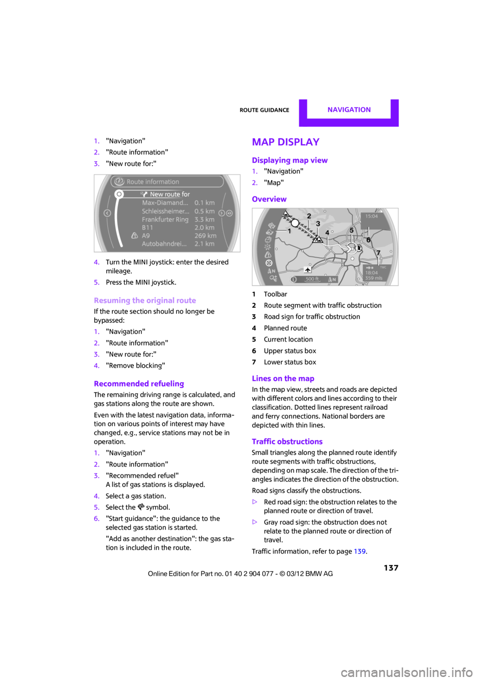
Overview
1Toolbar
2 Route segment with traffic obstruction
3 Road sign for traffic obstruction
4 Planned route
5 Current location
6 Upper status box
7 Lower status box
Lines on the map
In the map view, streets and roads are depicted
with different colors and lines according to their
classification. Dotted lines represent railroad
and ferry connections. National borders are
depicted with thin lines.
Traffic obstructions
Small triangles along the planned route identify
route segments with traffic obstructions,
depending on map scale. The direction of the tri-
angles indicates the dire ction of the obstruction.
Road signs classify the obstructions.
> Red road sign: the obstruction relates to the
planned route or direction of travel.
> Gray road sign: the obstruction does not
relate to the planned route or direction of
travel.
Traffic information, refer to page 139.
00320051004F004C00510048000300280047004C0057004C005200510003