tow MINI Hardtop 2 Door 2002 User Guide
[x] Cancel search | Manufacturer: MINI, Model Year: 2002, Model line: Hardtop 2 Door, Model: MINI Hardtop 2 Door 2002Pages: 140, PDF Size: 1.63 MB
Page 91 of 140

89
OVERVIEW REPAIRSOPERATIONCONTROLS DATA INDEX
WASHER FLUID ENGINE OILHeadlamp* and
windshield washer systemCapacity approx. 2.6 quarts (2.5 liters) per
reservoir.
Fill with water and Ð if required Ð with anti-
freeze (according to manufacturer's recom-
mendations).
We recommend that you mix the
washer fluid before adding it to the
reservoir.<
Antifreeze agent for the washer
systems is flammable. Always keep it
well away from sparks and open flames,
and store it in tightly closed containers well
out of the reach of children. Always observe
the instructions for use provided on the
container.<
Measuring the oil level 1. Park the vehicle on a level surface
2. Switch off the warmed-up engine
3. Pull the dipstick out after approx.
5 minutes and wipe it off with a lint-free
cloth, paper towel, or similar material
4. Carefully push the dipstick all the way
into the guide tube and pull it out again.
The oil level must be between the two
marks on the dipstick.
As with fuel economy, oil consumption is
directly influenced by your driving style and
vehicle operating conditions.
The oil volume between the two marks on
the dipstick ("MIN", "MAX") corresponds to
approx. 1.1 quarts (1 liter). Do not fill
beyond the upper notch on the dipstick.
Excess oil will damage the engine.
Page 102 of 140

100
ONBOARD TOOL KIT WINDSHIELD WIPER BLADESStorage locationThe illustration shows an example of the
tire change set.
Depending on the level of equipment, your
MINI is fitted with a special onboard tool
kit stored at the following locations:
Tire change set for space-saver spare tire:
In the luggage compartment under the
floor mat.
Tool bag for safety tires:
In the left of the luggage compartment,
behind the side trim panel beside the first-
aid kit, see page 113.
Windshield wiper1. Rotate the wiper arm completely out
from the windshield
2. Set the wiper blade at an angle
3. Press the securing spring (arrow)
4. Unhook the wiper blade towards the
windshield
5. Pull the wiper blade past the wiper arm
toward the top
6. Insert the new wiper blade
7. Press into position until you hear it
engage.
Use only wiper blades which have
been approved by the manufac-
turer.<
Rear window wiper1. Rotate the wiper arm completely out
from the windshield
2. Turn the wiper blade as far as it will go
to the rear, see arrow
3. Press the wiper blade against the limit
and thus out of the mounting
4. Press the new wiper blade into the
mounting.
Page 104 of 140

102
LAMPS AND BULBSTurn signal indicators, front 21 Watt bulb
1. Open the hood
2. Reach into the opening for the turn
signal indicators from above
3. Apply gentle pressure to the bulb holder
while turning it to the left
4. Remove and replace the bulb.Parking lamps and standing lamps 5 Watt bulb
The parking lamps and standing lamps are
integrated in the lamp housing of the turn
signal indicator.
1. Turn the bulb holder to the left and pull
out
2. Remove and replace the bulb.
Side turn signal indicators5 Watt bulb
1. Press the bulb towards the rear of the
vehicle and remove
2. Remove and replace the bulb.Side marker lampsSide marker lamps in the wheelhouse
paneling of the bumper.
Please contact a MINI center in case of a
malfunction.
Fog lamps* H7 bulb, 55 Watts
Please contact a MINI center in case of a
malfunction.
Page 108 of 140

106
REPAIRING A FLAT TIRE CHANGING TIRES Ð MINI WITH SPACE-SAVER SPARE TIRE
*
Safety measures in the event of a flat
tire:
Stop the vehicle as far as possible from
passing traffic. Switch on the hazard
warning flashers.
Turn the steering wheel to the straight-
ahead wheel position and engage the
steering lock. Engage the parking brake and
shift into 1st or reverse gear (selector lever
in P).
All passengers should be outside the
vehicle and well away from your imme-
diate working area (behind a guardrail, for
instance).
If a warning triangle or portable hazard
warning lamp is available, set it up on the
roadside at an appropriate distance from
the rear of the vehicle. Comply with all
safety guidelines and regulations.<
In the event of a flat tire, different proce-
dures should be followed depending on the
equipment included in your MINI:
>Vehicles with space-saver spare tire, see
next column
>Vehicles with safety tires, see page 110.
Additional safety measures in the
event of a wheel change: change the
wheel only on a level, firm surface which is
not slippery.
Avoid jacking the vehicle on a soft or slip-
pery support surface (snow, ice, loose
gravel, etc.), as either the vehicle or the jack
could slip sideways.
Do not use a wooden block or similar object
as a support base for the jack, as this would
prevent it from extending to its full support
height and reduce its load-carrying
capacity .
Do not lie under the vehicle or start the
engine when the vehicle is supported by
the jack Ð risk of fatal injury.<
To change a space-saver tire, proceed as
follows:
>Remove the space-saver spare tire, see
page 107
>Prepare the vehicle, see page 108
>Jack up the vehicle, see page 108
>Fit the space-saver spare tire, see
page 109
>Tighten the lug bolts, see page 109
>Drive with space-saver spare tire, see
page 109.
Tire change setOn vehicles with a space-saver spare tire,
the tire change set is stored in the luggage
compartment under the floor mat.
1 Chock, folding
2 Hubcap remover
3 Wheel stud wrench
4 Jack
5 Spanner
6 Tow fitting
7 Lifting handle
Page 110 of 140

108
CHANGING TIRES Ð MINI WITH SPACE-SAVER SPARE TIRE
*
9. Pull out the space-saver spare tire
towards the rear underneath the
vehicle
10. Position the space-saver spare tire with
the valve facing upwards
11. Unscrew the valve extension from the
valve of the space-saver spare tire
12. Unscrew the dust cap from the exten-
sion and attach to the space-saver
spare tire.
Preparing the vehicle
Read and comply with the safety
precautions provided on page 106.<
1. Secure the vehicle to prevent it from
rolling:
Place the folding chock behind the front
wheel on the other side of the vehicle;
on downward inclines, place it in front
of this wheel.
If the wheel is changed on a surface with
a more severe slope, take additional
precautions to secure the vehicle from
rolling
2. Loosen the lug bolts by a half turn.
Jacking up the vehicle1. Place the jack at the jacking point closest
to the wheel.
The jack base must be perpendicular to
the surface beneath the jacking point
Page 117 of 140

115
OVERVIEW REPAIRSOPERATION CONTROLS DATA INDEX
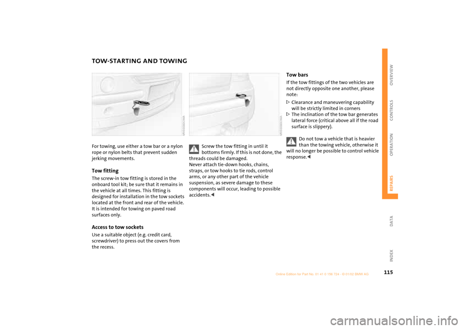
TOW-STARTING AND TOWINGFor towing, use either a tow bar or a nylon
rope or nylon belts that prevent sudden
jerking movements.Tow fittingThe screw-in tow fitting is stored in the
onboard tool kit; be sure that it remains in
the vehicle at all times. This fitting is
designed for installation in the tow sockets
located at the front and rear of the vehicle.
It is intended for towing on paved road
surfaces only. Access to tow socketsUse a suitable object (e.g. credit card,
screwdriver) to press out the covers from
the recess.
Screw the tow fitting in until it
bottoms firmly. If this is not done, the
threads could be damaged.
Never attach tie-down hooks, chains,
straps, or tow hooks to tie rods, control
arms, or any other part of the vehicle
suspension, as severe damage to these
components will occur, leading to possible
accidents.<
Tow barsIf the tow fittings of the two vehicles are
not directly opposite one another, please
note:
>Clearance and maneuvering capability
will be strictly limited in corners
>The inclination of the tow bar generates
lateral force (critical above all if the road
surface is slippery).
Do not tow a vehicle that is heavier
than the towing vehicle, otherwise it
will no longer be possible to control vehicle
response.<
Page 118 of 140

116
TOW-STARTING AND TOWINGTow-starting
On vehicles with Continuously Vari-
able automatic Transmission (CVT), it
is not permitted to start the engine by tow-
starting. The transmission could be
damaged.
For jump-starting, see page 113
.<
Only tow-start vehicles with a catalytic
converter when the engine is cold, other-
wise, unburned fuel in the catalytic
converter could catch fire. It is better to use
jumper cables.
1. Switch on the hazard warning flashers
(comply with national regulations)
2. Ignition key in position 2
3. Engage 3rd gear
4. Tow-start with the clutch pedal pressed
5. Slowly release the clutch
6. When the engine starts, press the clutch
pedal again
7. Switch off the hazard warning flashers.
Have the cause of the starting problems
rectified by your MINI center.
Towing
Only tow vehicles with Continuously
Variable automatic Transmission
(CVT) with the front wheels raised or on a
special transport vehicle, otherwise the
transmission can be damaged.<
1 Ignition key in position 1:
The brake lamps, turn signals, horn and
windshield wipers can be operated
2 Switch on the hazard warning flashers
(comply with national regulations).
If the electrical system has failed, place
some kind of warning on the towed vehicle,
e. g. a sign or warning triangle in the rear
window.
Ensure that if the electrical system
has failed the ignition key is in posi-
tion 1, otherwise the steering lock could
engage and make it impossible to steer the
vehicle.
When the engine is not running, there is no
power-assist. This means that greater
effort is required for braking and
steering.<
Towing with a commercial tow truck >Do not tow with sling-type equipment
>Use a wheel-lift or flatbed carrier
>Please comply with applicable towing
laws.
Never allow passengers to ride in a
towed vehicle for any reason.<
Page 130 of 140

EVERYTHING FROM A TO Z
128A
ABS (Antilock Brake
System) 16,
17,
78
Activated-charcoal filter 69
Adjusting
backrest 33
seats 31
steering wheel 35
thigh support 33
Air conditioner operation 65
automatic climate
control 68
Air conditioner system 64
Air distribution
air conditioner system 65
automatic climate
control 68,
69
Air pressure 80
Air recirculation 65,
68
Air supply
air conditioner system 65
automatic climate
control 69
Air vents 66,
69
Air, dry 65, 68
Airbags 16, 31,
37
All-season tires 85
Antenna 94 Antifreeze 91
Antilock Brake System
(ABS) 16,
17,
78
Aquaplaning 76
ASC+T (Automatic Stability
Control plus
Traction) 16, 17,
60
Ashtray 70
Automatic air distribution 68
Automatic air supply 68
Automatic car wash 94
Automatic cruise control 53
Automatic dimming of interior
rearview mirror 37
Automatic program, see
Automatic air
distribution 68
Automatic Stability Control
plus Traction
(ASC+T) 16,
17,
60
Average fuel consumption 59
Average speed 59
Axle loads 122
B
Backrest, adjusting 33
Backup lamps 45
bulb replacement 103
Bar, towing 115
Battery 111,
113,
114,
124
capacity 124
charge current 15
charging 111
maintenance 111
Battery changing
remote control 22
Battery, remote control 22
Beverage holder 70
Blower 65,
69
BMW 6
Bore 120
Brake 16
Brake fluid change 57
Brake fluid level 15,
79,
92
Brake hydraulic system 15
Brake lamp
bulb replacement 103
Brake pads 76,
79
Brake rotors 76
Brake system 76, 79
brake fluid 92
Brakes 79 Break-in procedure 76
Breaking in the vehicle 76
Bridging 113,
114
Bulb replacement 101
backup lamps 103
brake lamp, third 104
footwell lamps 105
front fog lamps 102
front turn signal
indicators 102
glove compartment
lamp 105
high beams 101
interior lamps 104
license plate lamp 104
low beams 101
luggage compartment
lamps 105
parking lamps 102
rear lamps 103
side turn signal
indicators 102
standing lamps 102
tail lamps 103
vanity mirror 105
Hilfsrahmen fŸr Querverweise
Page 131 of 140

EVERYTHING FROM A TO Z
129
OVERVIEW REPAIRS OPERATION CONTROLS DATA INDEX
C
California Proposition 65
Warning 97
Can holder, see Beverage
holder 70
Car wash 94
Car-care products 94
Care
chrome parts 94
floor mats 95
imitation leather 95
leather 95
light-alloy wheels 94
of upholstery 94
plastic parts 95
rubber parts 95
safety belts 95
special parts 94
windshield wipers 95
Cargo 72
securing 72
stowing 72
Caring for your vehicle 94
Cassette player, see separate
Owner's Manual
CD changer, see separate
Owner's Manual CD player, see separate
Owner's Manual
Center (high-mount) brake
lamp
bulb replacement 104
Central locking system 23,
26
Changing tires
space-saver spare tire 106
Child seat 38
Child-restraint systems 38
Chrome parts 94
Cigarette lighter 70
socket 70
Cleaning rear window 52
Cleaning windshield 52
Clock 58
Closing
from inside 26
from outside 23
Clothes hooks 77
Clutch 76
Cockpit 12
Combination of wheels/
tires 84
Compact Disc player, see
separate Owner's Manual
Compression ratio 120 Computer 58
average fuel
consumption 59
average speed 59
cruising range 59
exterior temperature 59
Condensation 65,
68
Consumption 59
Consumption display 55
Contents 2
Continuously Variable
automatic Transmission
(CVT)
electronic transmission
control module (EP) 48
gear display 48
ignition 42
interlock 42
manual mode 47
parking 47
reverse gear 47
selector lever
shiftlock 42,
46
shiftlock 46
Sport program 47
Steptronic 46
towing 116
tow-starting 116
transmission fault 48 Control elements 12
Convenience feature
sliding/tilt sunroof 25
windows 25
Convenience operation
via central locking
system 26
Coolant 91
Coolant level 91
Coolant temperature
gauge 56
Cooling 65,
68
Copyright notice 6
Correct sitting posture with
airbags 31
safety belt 31
Cruise control 17,
18,
53
Cruising range 59
Cup holder, see Beverage
holder 70
Curb weight 122
Currency of the Owner's
Manual 7
Cylinders 120
Page 132 of 140

EVERYTHING FROM A TO Z
130D
Dashboard 12
Data
dimensions 121
engine 120
weights 122
Data, technical 120
Daytime driving lamps 49
Decommissioning the
vehicle 96
Deep water, see Water on
roadways 77
Defrosting position 66
Defrosting windows 69
air conditioner system 66
automatic climate
control 69
Dimensions 121
Dirt on the paintwork 94
Disc brakes 79
Displacement 120
Display elements 13,
14
coolant temperature
gauge 56
fuel gauge 55
indicator and warning
lamps 15
odometer 55
Service Interval Display 57
with navigation system 14 Display lighting 50
Distance remaining 59
Door keys 22
Doors
locking 24
manual operation 25
remote control 23
unlocking 24
DOT Quality Grades 83
Drink holder, see Beverage
holder 70
Driving lamps 49
Driving notes, general 76
Dry air 65,
68
Dynamic Stability Control
(DSC) 16, 61
E
Easy Entry 33
EBV (Electronic Brake Force
Distribution) 16
Electric power windows 28
Electrical defect
driver's door 25
sliding/tilt sunroof 30
Electrical system 124
Electronic Brake Force
Distribution (EBV) 16 Electronic transmission control
module (EP), Continuously
Variable automatic
Transmission (CVT) 48
Emergency operation
driver's door 25
sliding/tilt sunroof 30
tailgate 27
Engine 76
electronics 17
power output 17
speed 17,
55
starting 42
switching off 43
Engine compartment
MINI COOPER 87
MINI COOPER S 88
Engine oil 89
additives 90
prescribed oils 90
pressure 15
Entry to the rear 33
EP (electronic transmission
control module),
Continuously Variable
automatic Transmission
(CVT) 48
Exterior finish, care 94
Exterior mirrors 36
Eyelets, towing 115
F
Failure, tires 62,
106,
110
Filler cap cover 77
Filling capacities 123
Filling, tank 123
First-aid kit 113
Flat tire 62,
106
Flat Tire Monitor 16,
17,
62
Floor carpets 95
Floor coverings 95
Floor mats 95
Fog lamps 50
Foldable rear backrest 71
"Follow me home" lamps 49
Footbrake 79
Footwell lamps
bulb replacement 105
Front fog lamps 50
bulb replacement 102
Front seat adjustment 31
Fuel consumption 59
Fuel consumption display 55
Fuel gauge 55
Fuel preparation 120
Fuel quality 78
Fuel reserve indicator 55
Fuel tank capacity 123
Fuses 112