engine MINI Hardtop 2 Door 2002 Owner's Manual
[x] Cancel search | Manufacturer: MINI, Model Year: 2002, Model line: Hardtop 2 Door, Model: MINI Hardtop 2 Door 2002Pages: 140, PDF Size: 1.63 MB
Page 5 of 140
3
OVERVIEW REPAIRS OPERATION CONTROLS DATA INDEX
Driving:
Ignition lock 42
Starting the engine 42
Switching off the engine 43
Parking brake 44
Manual transmission 45
Continuously Variable automatic
Transmission (CVT) 46
Parking lamps/Low beams 49
Indicator/Headlamp flasher 49
Instrument lighting 50
Fog lamps 50
Interior lamps 50
Light-emitting diodes 51
Washer/Wiper system 51
Cruise control 53
Everything under control:
Odometer 55
Tachometer 55
Fuel gauge 55
Coolant temperature gauge 56
Service Interval Display 57
Clock 57
Computer 58
Technology for safety and driving
convenience:
Automatic Stability Control plus Traction
(ASC+T) 60
Dynamic Stability Control (DSC) 61
Flat Tire Monitor 62
Park Distance Control (PDC) 63
Controlling the climate for pleasant
driving:
Air conditioner system 64
Automatic climate control 67
Interior conveniences:
Glove compartment 70
Ashtray/Beverage holder 70
Cigarette lighter 70
Loading and transporting cargo:
Luggage compartment cover 71
Foldable rear backrest 71
Loading cargo 72
Roof-mounted luggage rack 73
Care and maintenance
Special operating instructions:
Break-in procedures 76
General driving notes 76
Refueling 77
Fuel specifications 78
Antilock Brake System (ABS) 78
Brake system 79
Wheels and tires:
Tire inflation pressure 80
Tire condition 82
Tire replacement 83
Wheel and tire combinations 84
Winter tires 85
Snow chains 85
Page 6 of 140
CONTENTS
4
In the engine compartment:
Hood 86
Engine compartment Ð
MINI COOPER 87
Engine compartment Ð
MINI COOPER S 88
Washer fluid 89
Engine oil 89
Coolant 91
Brake fluid 92
Maintenance and care:
MINI Maintenance System 93
Caring for your vehicle 94
Vehicle immobilization 96
Laws and regulations:
OBD interface socket 96
Technical modifications 96
California Proposition 65 Warning 97
Owner Service Procedures
Replacement procedures:
Onboard tool kit 100
Windshield wiper blades 100
Lamps and bulbs 101
Repairing a flat tire 106
Changing tires Ð MINI
with space-saver spare tire 106
Flat tire Ð safety tires 110
Battery 111
Fuses 112
Giving and receiving assistance:
Warning triangle 113
First-aid kit 113
Jump-starting 113
Tow-starting and towing 115
Technical data
Engine data 120
Dimensions 121
Weights 122
Capacities 123
Electrical system 124
Page 15 of 140

13
OVERVIEW REPAIRS OPERATION CONTROLS DATA INDEX
DISPLAY ELEMENTS
1 Tachometer 55
with indicator and warning lamps, see
from page 15
2 Display for computer 58
3 Speedometer with indicator and warning
lamps, see from page 154 Indicator for
>
Odometer 55
>
Trip odometer 55
>
Service Interval 57
>
Program display for Continuously
Variable Transmission (CVT) 485 Trip odometer, reset to zero 55
6 Fuel gauge 55
7 Engine coolant temperature gauge 56
Page 17 of 140
15
OVERVIEW REPAIRS OPERATION CONTROLS DATA INDEX
INDICATOR AND WARNING LAMPS
Technology
that monitors itself
The system runs a check on the warning
and indicator lamps marked by "
l
" each
time you switch on the ignition. They each
light up once for different periods of time.
If a malfunction should occur in one of
these systems, the corresponding lamp
does not go out after the engine is started
or it lights up while the vehicle is moving.
You will see how to react correctly to this
below.
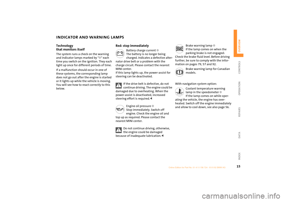
Red: stop immediately
Battery charge current
l
The battery is no longer being
charged. Indicates a defective alter-
nator drive belt or a problem with the
charge circuit. Please contact the nearest
MINI center.
If this lamp lights up, the power-assist for
steering can be deactivated.
If the drive belt is defective, do not
continue driving. The engine could be
damaged due to overheating. When the
power-assist is deactivated, increased
steering effort is required.
<
Engine oil pressure
l
Stop immediately. Switch off
engine. Check the engine oil and
top up as required. Please contact the
nearest MINI center.
Do not continue driving, otherwise,
the engine could be damaged
because of inadequate lubrication.
<
Brake warning lamp
l
If the lamp comes on when the
parking brake is not engaged:
Check the brake fluid level. Before driving
further, be sure to comply with the infor-
mation on pages 79, 57 and 92.
Brake warning lamp for Canadian
models.
With navigation system option:
Coolant temperature warning
lamp in the speedometer
l
If the lamp comes on while oper-
ating the vehicle, the engine has over-
heated. Switch off the engine immediately
and allow to cool down, see also page 56.
Page 19 of 140
17
OVERVIEW REPAIRS OPERATION CONTROLS DATA INDEX
INDICATOR AND WARNING LAMPS
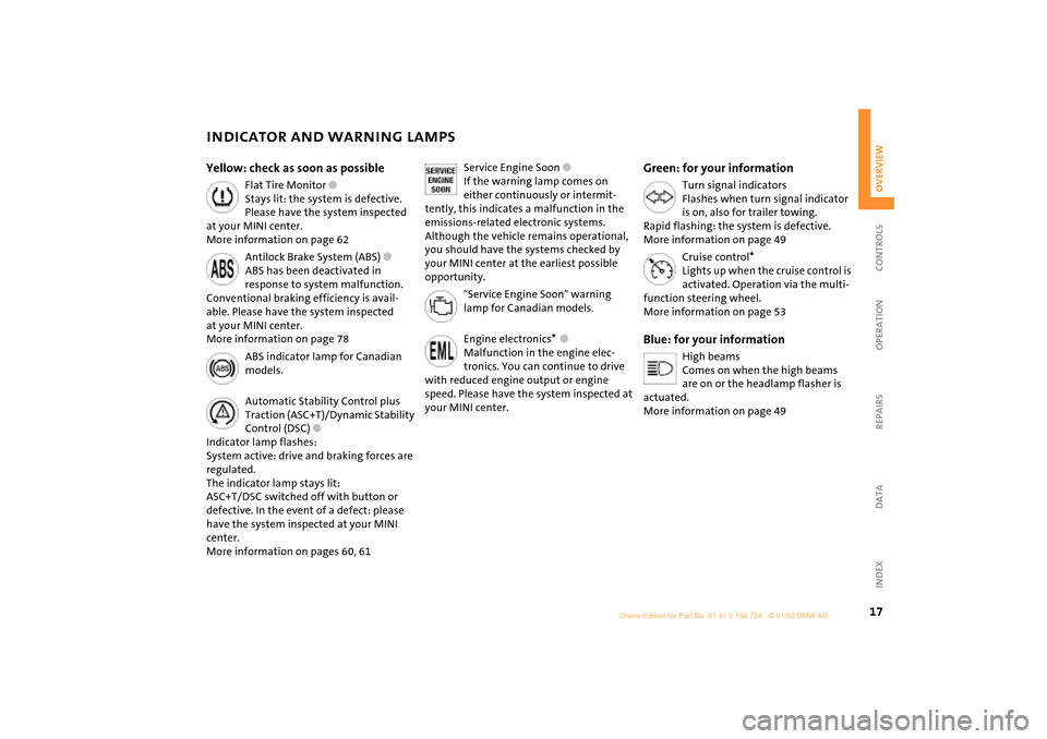
Yellow: check as soon as possible
Flat Tire Monitor
l
Stays lit: the system is defective.
Please have the system inspected
at your MINI center.
More information on page 62
Antilock Brake System (ABS)
l
ABS has been deactivated in
response to system malfunction.
Conventional braking efficiency is avail-
able. Please have the system inspected
at your MINI center.
More information on page 78
ABS indicator lamp for Canadian
models.
Automatic Stability Control plus
Traction (ASC+T)/Dynamic Stability
Control (DSC)
l
Indicator lamp flashes:
System active: drive and braking forces are
regulated.
The indicator lamp stays lit:
ASC+T/DSC switched off with button or
defective. In the event of a defect: please
have the system inspected at your MINI
center.
More information on pages 60, 61
Service Engine Soon
l
If the warning lamp comes on
either continuously or intermit-
tently, this indicates a malfunction in the
emissions-related electronic systems.
Although the vehicle remains operational,
you should have the systems checked by
your MINI center at the earliest possible
opportunity.
"Service Engine Soon" warning
lamp for Canadian models
.
Engine electronics
*
l
Malfunction in the engine elec-
tronics. You can continue to drive
with reduced engine output or engine
speed. Please have the system inspected at
your MINI center.
Green: for your information
Turn signal indicators
Flashes when turn signal indicator
is on, also for trailer towing.
Rapid flashing: the system is defective.
More information on page 49
Cruise control
*
Lights up when the cruise control is
activated. Operation via the multi-
function steering wheel.
More information on page 53
Blue: for your information
High beams
Comes on when the high beams
are on or the headlamp flasher is
actuated.
More information on page 49
Page 30 of 140

28
ELECTRIC POWER WINDOWSOpen and close windowsFrom ignition key position 1:
To open:
Press the switch downwards.
The window opens until you release the
switch
or
briefly press the switch downwards.
The window opens automatically.
Pressing the switch again stops the opera-
tion.
To close:
Press the switch upwards.
The window closes until you release the
switch
or
when the engine is running:
Briefly press the switch upwards.
The window closes automatically.
Pressing the switch again stops the opera-
tion.
The window on the front passenger
side cannot be closed automati-
cally.<
Watch during the closing process to
be sure that no one is injured.<
After the ignition has been switched off:
You can use the electric power windows as
long as no one opens any of the doors.
If a door is opened during operation, the
opening/closing process stops immedi-
ately.
When leaving the vehicle, always
remove the ignition key from the
lock and remember to close the doors to
prevent children from operating the power
windows and injuring themselves, etc.<
For the convenience mode via the door
lock, refer to page 25.
Page 40 of 140

38
AIRBAGS TRANSPORTING CHILDRENDo not make any changes yourself to the
individual components and wiring. This
includes the padded cover of the steering
wheel, in the instrument panel and the roof
supports, as well as the sides of the roof-
liner and the original backrest covers on the
front seats. Do not attempt to remove or
dismantle the steering wheel. In view of
the applicable safety regulations, arrange
for your MINI center to dispose of the
airbag generators. Unprofessional
attempts to service the system could lead
to failure in an emergency or undesired
airbag activation, either of which could
result in personal injury. Do not touch the
individual components directly after the
system has been triggered, as otherwise
there is a danger of burns.<
At all times, occupants should sit
upright and be properly restrained
(infants and small children in appropriate
child-restraint systems; larger children and
adults using the safety belts). Never let an
occupant's head rest near or on a head
airbag because the inflating airbag could
cause serious or fatal injury. A child which
is not properly restrained could place his or
her head on or near the airbag.<
Indicator lamp
The indicator lamp on the instru-
ment panel shows the airbag
system status starting from igni-
tion key position 1.
System operational:
>The indicator lamp comes on briefly.
System malfunction:
>The indicator lamp does not come on
>The indicator lamp fails to go out after
the engine has been started, or it comes
on during normal driving.
A system defect could prevent the airbags
from deploying in response to a severe
impact occurring within the system's
normal triggering range.
Have the system checked as soon as
possible by your MINI center.
Children younger than 13 years and/or
smaller than 5 ft (150 cm) should only
travel in the rear in suitable restraint
systems.
Commercially-available child-restraint
systems are designed to be secured with a
lap belt or with the lap belt portion of a
combination lap/shoulder belt. Improperly
or inadequately installed restraint systems
can increase the risk of injury to children.
Always read and follow the instructions
that come with the system.
If you use a child-restraint system with a
tether strap:
Page 43 of 140
41
OVERVIEW REPAIRS OPERATIONCONTROLS DATA INDEX
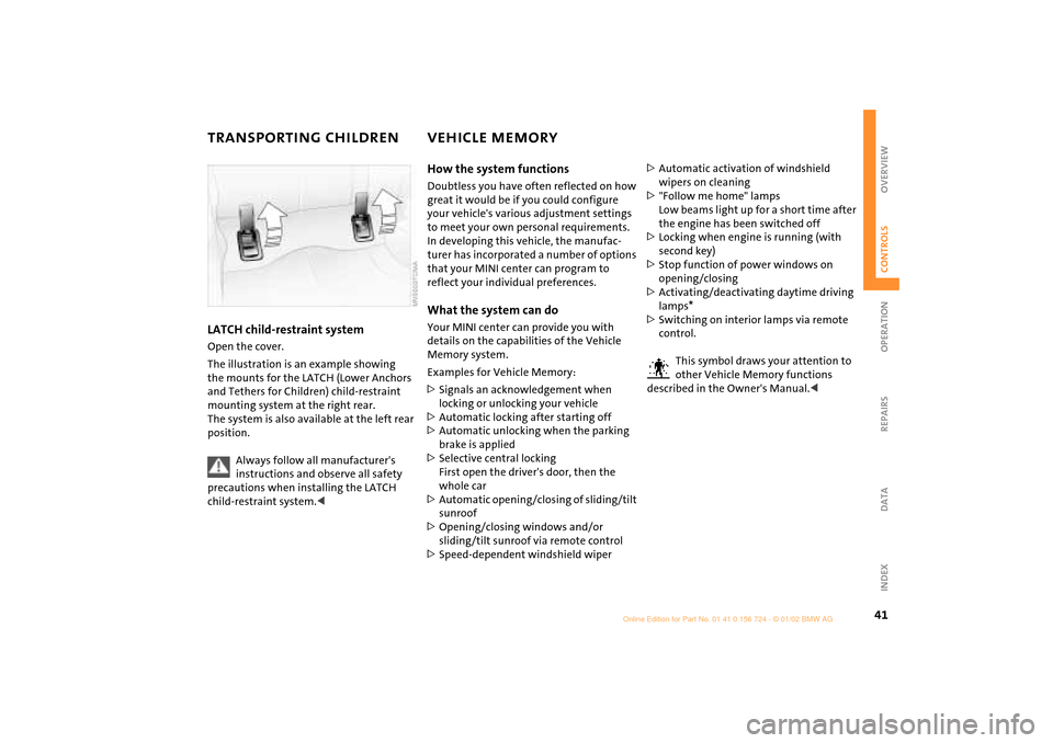
TRANSPORTING CHILDREN VEHICLE MEMORY LATCH child-restraint systemOpen the cover.
The illustration is an example showing
the mounts for the LATCH (Lower Anchors
and Tethers for Children) child-restraint
mounting system at the right rear.
The system is also available at the left rear
position.
Always follow all manufacturer's
instructions and observe all safety
precautions when installing the LATCH
child-restraint system.<
How the system functionsDoubtless you have often reflected on how
great it would be if you could configure
your vehicle's various adjustment settings
to meet your own personal requirements.
In developing this vehicle, the manufac-
turer has incorporated a number of options
that your MINI center can program to
reflect your individual preferences. What the system can doYour MINI center can provide you with
details on the capabilities of the Vehicle
Memory system.
Examples for Vehicle Memory:
>Signals an acknowledgement when
locking or unlocking your vehicle
>Automatic locking after starting off
>Automatic unlocking when the parking
brake is applied
>Selective central locking
First open the driver's door, then the
whole car
>Automatic opening/closing of sliding/tilt
sunroof
>Opening/closing windows and/or
sliding/tilt sunroof via remote control
>Speed-dependent windshield wiper>Automatic activation of windshield
wipers on cleaning
>"Follow me home" lamps
Low beams light up for a short time after
the engine has been switched off
>Locking when engine is running (with
second key)
>Stop function of power windows on
opening/closing
>Activating/deactivating daytime driving
lamps
*
>Switching on interior lamps via remote
control.
This symbol draws your attention to
other Vehicle Memory functions
described in the Owner's Manual.<
Page 44 of 140

42
IGNITION LOCK STARTING THE ENGINE 0 Steering locked
1 Steering unlocked
2 Ignition switched on
3 Starting the engine0 Steering locked The key can be inserted or removed in this
position only.
To lock the steering:
1. Remove the key
2. Turn the steering wheel slightly to the
left or right until the lock engages.
Vehicles with Continuously Variable
automatic Transmission (CVT):
Do not move the selector lever from posi-
tion "P" until the engine is running.
Your vehicle is equipped with an interlock.
Therefore, the ignition key cannot be
turned to position 0 and removed until the
selector lever is in position "P" (Interlock).<
1 Steering unlocked Individual electrical accessories are ready
for operation.
You will find that it is often easier to turn
the ignition key from position 0 to posi-
tion 1 when you move the steering wheel
slightly to help disengage the lock.2 Ignition switched onAll electrical accessories are ready for oper-
ation.3 Starting the engine
Vehicles with manual transmission:
Step on the clutch when starting the
vehicle. A lockout prevents the engine from
starting if the clutch is not depressed.<
Do not allow the engine to warm up with
the vehicle at a standstill. Move off imme-
diately at a moderate engine speed.
Do not allow the engine to run in
enclosed spaces. The exhaust gases
contain carbon monoxide, an odorless and
colorless, but highly toxic gas.
Breathing the exhaust gases poses an
extreme health risk, and can lead to uncon-
sciousness and death.
Do not leave the vehicle unattended with
the engine running. An unattended vehicle
with a running engine represents a poten-
tial safety hazard. When driving, standing
at idle or when parking, take precautions to
avoid contact between the hot exhaust
system and easily flammable materials
(grass, hay or leaves, for example). Such
contact could lead to a fire, resulting in
serious personal injury and property
damage.<
Page 45 of 140

43
OVERVIEW REPAIRS OPERATIONCONTROLS DATA INDEX
STARTING THE ENGINE SWITCHING OFF THE ENGINE StartingWhen starting the engine, do not press the
accelerator pedal.
Do not actuate the starter for too
short a time. Do not turn it for more
than approx. 20 seconds. Release the igni-
tion key immediately when the engine
starts.
Extended starting attempts, characterized
by excessively frequent or long periods
with the starter engaged, can lead to
damage in the catalytic converter.<
If the engine does not start on the first
attempt (the engine is very hot or cold, for
instance):
>Press the accelerator pedal halfway
down while engaging the starter.
Cold starts at extremely low temperatures
(as of approx. +5 7(Ð15 6)):
>Press the accelerator pedal halfway
down while engaging the starter
>For the initial start attempt, allow the
starter to remain engaged somewhat
longer (approx. 10 seconds).
Manual transmission1. Engage the parking brake
2. Put the manual gearshift lever in neutral
3. Press the clutch pedal
4. Start the engine.Continuously Variable automatic
Transmission (CVT)*1. Press the footbrake
2. Put the selector lever in position P or N
3. Starting the engine.
Move the selector lever to position N
and engage the parking brake before
leaving your vehicle with the engine
running.
Do not leave the vehicle with the engine
running. An unattended vehicle with a
running engine represents a potential
safety hazard.<
You should never remove the ignition
key when the vehicle is in motion, as
the steering lock could engage.
When you leave the vehicle, always remove
the ignition key and engage the steering
lock.
When you park on downward slopes,
engage the parking brake.<
Manual transmissionTurn the ignition key to position 1 or 0.Continuously Variable automatic
Transmission (CVT)*Engage selector lever position P, turn the
ignition key to position 1 or 0.