ECU MINI Hardtop 2 Door 2004 User Guide
[x] Cancel search | Manufacturer: MINI, Model Year: 2004, Model line: Hardtop 2 Door, Model: MINI Hardtop 2 Door 2004Pages: 152, PDF Size: 1.41 MB
Page 97 of 152

95
OVERVIEW REPAIRSOPERATIONCONTROLS DATA INDEX
BONNET
Do not attempt to service your vehi-
cle if you do not have the required
technical background. Before working in
the engine compartment, switch off the
engine and allow it to cool down. Before
working on the electrical system, always
disconnect the battery first. For all work on
the vehicle, comply with the appropriate
information and instructions. If you are not
familiar with the guidelines, the manufac-
turer of your MINI recommends that you
have the service work performed by your
MINI Dealer. Otherwise, work improperly
carried out on the parts and components
can pose a safety hazard for vehicle occu-
pants and other road users.<
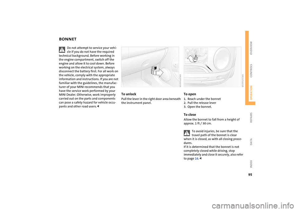
To unlockPull the lever in the right door area beneath
the instrument panel.
To open1. Reach under the bonnet
2. Pull the release lever
3. Open the bonnet.To closeAllow the bonnet to fall from a height of
approx. 1 ft / 30 cm.
To avoid injuries, be sure that the
travel path of the bonnet is clear
when it is closed, as with all closing proce-
dures.
If it is determined that the bonnet is not
completely closed while driving, stop
immediately and close it securely, also refer
to page 16.<
Page 112 of 152

110
ONBOARD TOOL KIT WINDSHIELD WIPER BLADES The picture shows as an example the tire
change set with onboard tools for vehicles
with the space-saver spare tire.
Depending on the level of equipment
options, your MINI is fitted with a special
onboard tool kit stored at the locations
described below:
Storage locationMINI Mobility System with tire change set
and onboard tools:
>In the cargo area under the floor mat.
Tire change set and onboard tools for Run
Flat tires:
>Tire change set:
In the cargo area in a separate pouch,
refer to page 123
>Onboard tool kit:
on the left-hand side of the cargo area
behind the side trim panel.
Tire change set with space-saver spare tire:
>In the cargo area under the floor mat.
Windshield wiper1. Rotate the wiper arm completely out
from the windshield
2. Set the wiper blade at an angle
3. Press the securing spring, arrow
4. Unhook the wiper blade towards the
windshield
5. Pull the wiper blade past the wiper arm
toward the top
6. Insert the new wiper blade
7. Press into position until you hear it
engage.
Page 120 of 152

118
CHANGING TIRES: MINI WITH SPACE-SAVER SPARE TIRE
*
3. Screw the lifting handle from the
onboard tool kit onto the thread
4. Raise the lifting handle slightly
5. Squeeze the securing springs
6. The space-saver spare tire is released
and must be held by the lifting handle
7. Lower the space-saver spare tire with
the lifting handle
8. Unscrew the lifting handle again
9. Pull out the space-saver spare tire
towards the rear underneath the vehi-
cle
10. Position the space-saver spare tire with
the valve facing upwards
11. Unscrew the valve extension from the
valve of the space-saver spare tire
12. Unscrew the dust cap from the exten-
sion and attach to the valve on the
spare tire.
Due to its different dimensions, the
damaged wheel cannot be placed in
the recess for the space-saver spare tire.<
Page 121 of 152

119
OVERVIEW REPAIRSOPERATION CONTROLS DATA INDEX
CHANGING TIRES: MINI WITH SPACE-SAVER SPARE TIRE
*
Preparing for a tire change
Follow the safety precautions on
pages 116 and 117.<
1. Secure the vehicle to prevent it from roll-
ing:
Place the folding chock behind the front
wheel on the other side of the vehicle;
on downward inclines, place it in front of
this wheel.
If the wheel is changed on a surface with
a more severe slope, take additional pre-
cautions to secure the vehicle from roll-
ing
2. Loosen the lug bolts by a half turn.
Jacking up the vehicle 1. Place the jack at the jacking point closest
to the wheel.
The jack base must be perpendicular to
the surface beneath the jacking point
The vehicle jack is designed for
changing wheels only. Do not
attempt to raise another vehicle model
with it or to raise any load of any kind. To
do so could cause accidents and personal
injury.<
2. During jacking up, insert the jack head in
the square recess of the jacking point
3. Jack the vehicle up until the wheel you
are changing is raised from the ground.
Page 122 of 152

120
CHANGING TIRES: MINI WITH SPACE-SAVER SPARE TIRE
*
Fitting the space-saver spare tire
1. Unscrew the lug bolts and remove the
wheel
2. Remove accumulations of mud or dirt
from the mounting surfaces of the
wheel and hub. Clean the lug bolts
3. Fit the space-saver spare tire
4. Screw at least two lug bolts finger-tight
into opposite bolt holes
5. Screw in the remaining bolts
6. Tighten all the lug bolts firmly in a diag-
onal pattern
7. Lower the vehicle
8. Remove the jack.Tightening the lug bolts Tighten the lug bolts in a diagonal pattern.
As soon as possible, have the secure
seating of the lug bolts, tightening
torque 88.5 lb ft / 120 Nm, checked using a
calibrated torque wrench. Otherwise, a
wheel coming loose can lead to a severe
accident.<
Replace the defective tire as soon as possi-
ble and have the new wheel/tire assembly
balanced.
Driving with the space-saver spare tireDrive cautiously. Do not exceed a speed of
50 mph / 80 km/h.
You must expect changes in vehicle han-
dling such as lower track stability during
braking, longer braking distances and
changes in self-steering properties when
close to the handling limit. These effects
are more pronounced when driving with
winter tires.
Only one space-saver spare tire may
be mounted at one time. Reinstall a
wheel and tire of the original size as soon
as possible.<
Check the tire inflation pressure at
the earliest opportunity and correct it
if necessary.<
Page 126 of 152

124
BATTERYLocation in the MINI COOPERThe battery is located in the engine com-
partment.
Exact location, refer to page 96.Location in the MINI COOPER SThe battery is located in the cargo area
under the floor mat.Battery careThe battery is absolutely maintenance-free,
that is, the original electrolyte will normally
last for the service life of the battery under
moderate climatic conditions.
For all questions regarding the bat-
tery, please consult your MINI
Dealer.<
Charging the batteryOnly charge the battery in the vehicle via
the terminals in the engine compartment
with the engine switched off, refer to
'Jump-starting', page 126 ff.Disposal
Return used batteries to a recycling
point or your MINI Dealer. Maintain
the battery in an upright position for trans-
port and storage. Secure the battery to pre-
vent it from tilting during transport.<
Page 145 of 152

EVERYTHING FROM A TO Z
143
OVERVIEW REPAIRS OPERATION CONTROLS DATA INDEX
Intermittent operation
wipers 50
Interval display, service 102
J
Jack, refer to Tire change set
MINI Mobility System 121
Run Flat tires 93
space-saver spare tire 117
Jacking points 119
Jets, refer to Ventilation 69, 72
Jets, refer to Windshield
washer jets 51
Jump-starting 126
K
Keys 22
Kickdown 46
Knock control 85
L
Lamp defect 111
Lamp replacement, refer to
Lamps and bulbs 111
Lamps and bulbs 111
Lamps, refer to Parking lamps/
Low beams 48
Lashing eyes, refer to Securing
the load 77
LATCH child-restraint
mounting system 40 Leather care 105
LEDs light-emitting diodes 50
Length, refer to
Dimensions 133
License plate lamp
bulb replacement 115
Lifting handle, space-saver
spare tire, refer to Tire
change set 117
Light switch 48
Light-alloy wheels, care 104
Light-emitting diodes 50
Lighter 74
'Lights on' warning 48
Load securing devices, refer to
Securing the load 77
Loading cargo
vehicle 76
Loads, refer to Loading cargo 76
Locking
from inside 26
from outside 24
Low beams 48
bulb replacement 112
Lower back support, refer to
Lumbar support 33
Luggage compartment
capacity, refer to Cargo area
volume 134
Luggage compartment cover,
refer to Cargo area cover 75 Luggage compartment lamps,
refer to Cargo area lamps 116
Luggage compartment lid
emergency operation, refer
to Manual operation 27
Luggage compartment lid, refer
to Tailgate 27
Luggage compartment, refer to
Cargo area 75
Luggage rack, refer to Roof-
mounted luggage rack 78
Lumbar support 33
M
M+S tires, refer to Winter
tires 92
Maintenance system 102
Maintenance, refer to Service
interval display 56, 102
Malfunction
door lock 25
glass sunroof, electric 30
tailgate 27
Manual mode, refer to
Continuously Variable
automatic Transmission
(CVT) 46 Manual operation
door lock 25
driver's door 25
fuel filler cap 84
glass sunroof, electric 30
tailgate 27
Manual transmission 44
Manufacturer 6
Master key
initializing 22
with remote control 22
MC operation, refer to
Owner's Manual for Radio
Memory, refer to Vehicle
Memory 37
MFL Multifunction steering
wheel 18
Microfilter
air conditioning system 69
automatic climate control 72
MINI Maintenance System 102
MINI manufacturer 6
MINI Mobility System 121
compressor 122
liquid sealant 122
Mirrors 36
heating 36
Mobility System 121
Modifications, technical, refer
to For your own safety 7
Page 147 of 152

EVERYTHING FROM A TO Z
145
OVERVIEW REPAIRS OPERATION CONTROLS DATA INDEX
Rear turn signal indicator
bulb replacement 113
Rear window wiper 51
replacement 111
Rearview mirror 36
Recirculated air mode
air conditioning system 68
automatic climate control 71
Reclining seat, refer to Backrest
tilt 33
Refueling 84
Remaining distance for
service 56
Remaining distance, refer to
Range 58
Remote control 23
changing battery 22
initializing 22
malfunctions 25
Remote control key, refer to
Master key with remote
control 22
Replacement key 22
Replacement of tires 92
changing tires 117
Reporting safety defects 9
Reserve indicator light, refer to
Fuel gauge 54, 55
Reservoir
washer system 98 Restraint systems
for children 38
refer to Safety belts 35
Reverse
Continuously Variable
automatic Transmission
(CVT) 46
manual transmission 44
Rod antenna 103
Roller sun blind 30
Roof load, refer to Weights 134
Roof-mounted luggage rack 78
Rope, refer to Towing 128
RSC Runflat System
Component, refer to Run Flat
tires 93
Rubber parts 104
Run Flat tires 93
tire failure 93
tire inflation pressure 87
Runflat System Component
(RSC), refer to Run Flat
tires 93
S
Safety belt height
adjustment 35 Safety belts 35
care 104
height adjustment 35
safe seating position 31
warning lamp 16, 35
Safety lock buttons, doors,
refer to Locking 26
Safety systems, refer to
All Season traction Control
(ASC) 59
Antilock Brake System
(ABS) 61
Dynamic Stability Control
(DSC) 60
Screwdriver, refer to Onboard
tool kit 110
Seat adjustment 32
Seat heating 35
Securing loads, refer to Loading
cargo 76
Securing the load 77
Securing the vehicle
from inside 26
from outside 24
Selector lever
Continuously Variable
automatic Transmission
(CVT) 45 Selector lever positions
Continuously Variable
automatic Transmission
(CVT) 45
Selector lever shiftlock, refer to
Shiftlock 45
Service 56
Service interval display 56, 102
Service, refer to Service and
Warranty Information
Booklet for US models,
Warranty and Service Guide
Booklet for Canadian
models 102
Shifting
Continuously Variable
automatic Transmission
(CVT) 46
manual transmission 44
Shifting gears, refer to
Continuously Variable
automatic Transmission
(CVT) 45
Shiftlock, refer to Range
selection 45
Side airbags 65
Side turn signal indicators
bulb replacement 113
Signal horn, refer to Horn 12