change time MINI Hardtop 2 Door 2005 Owner's Manual
[x] Cancel search | Manufacturer: MINI, Model Year: 2005, Model line: Hardtop 2 Door, Model: MINI Hardtop 2 Door 2005Pages: 165, PDF Size: 2.32 MB
Page 27 of 165
25
OVERVIEW REPAIRS OPERATIONCONTROLS DATA INDEX
OPENING AND CLOSING: FROM OUTSIDEVia remote controlWhen the vehicle is unlocked or locked, the
anti-theft system is also deactivated/acti
-
vated and the interior lamp is switched on/
off.
Children might be able to lock the doors from the inside. Always take
the vehicle keys with you so that the vehi
-
cle can be opened again from the outside at
any time.
15 of the FCC, Federal Communi
-
cations Commission, regulations. Opera
-
tion is governed by the following: FCC ID: LX8765S
LX8765ELX8CAS
Compliance statement:This device complies with part
15 of the
FCC Rules. Operation is subject to the fol
-
lowing two conditions:>This device may not cause harmful inter
-
ference, and>this device must accept any interference
received, including interference that may
cause undesired operation.
Any unauthorized modifications or changes to these devices could void
the user's authority to operate this equip
-
ment.<
Page 81 of 165
79
OVERVIEW REPAIRS OPERATIONCONTROLS DATA INDEX
AUTOMATIC CLIMATE CONTROL
*
Automatic air distribution and volume
Automatic program (AUTO):
Indicator lamp lights up.
Automatic adjustment of the air distribu
-
tion and volume, and adaptation of the
specified temperatures to external influ
-
ences, i.e. outside temperature and sun
-
light.In the automatic program (AUTO), the air
conditioning is activated automatically. To
create a pleasant air climate, the air tem
-
perature coming from the vents in the
upper body area is lower than the air tem
-
perature in the footwell.Air volume/Blower
Switching automatic climate control
off/on
Air volume/Blower.
Press the left or right half of the
button. The air volume varies. Automatic
adjustment of the air volume is deacti
-
vated.Switching air conditioner on/off.
Press the left half of the button while the
blower is at the lowest setting. The blower,
heating and air conditioning are switched
off. All displays go out.
Switch the automatic climate control back
on by pressing any button.Air conditioning
Indicator lamp lights up.
The air is cooled and dehumidified
and, depending on the temperature set
-
ting, rewarmed.In the automatic program (AUTO), the air
conditioning is activated automatically. After the engine has started, the wind
-
shield can temporarily fog over. In the air
conditioning mode, there is less condensa
-
tion on the windows.
When the air conditioning is on, con
-
densation is formed which then exits
under the vehicle. Traces of condensed
water on the ground are therefore nor
-
mal.
-
cle is blocked. indicator lamp lights
up.
The air within the vehicle is recirculated.In the automatic program (AUTO) in hot
weather conditions, the recirculated air
mode is activated temporarily to enable
faster cooling.
The indicator lamp for the recirculated air
button is not lit.
The recirculated air mode should not be constantly used over a longer period of
time, as the air quality in the vehicle's interior
will otherwise gradually deteriorate. If the
windows fog up in the recirculated air mode,
turn the recirculated air mode off and if nec
-
essary increase the air supply.
<
Rear window defroster and windshield
heating*
Indicator lamp lights up.
As long as the indicator lamp is lit,
the window heater is operating.
The heater switches off automatically after a
short time. Temperature
Tap or turn the wheel in the appro
-
priate direction to change the tem
-
perature step by step.The figures in the display provide a
general indication of interior temperature.
When you start the vehicle, the system
ensures that the selected temperature is
achieved as quickly as possible and then main
-
tained.
Page 82 of 165
80
AUTOMATIC CLIMATE CONTROL
*
Permanent heating with maximum power output at temperature selec
-
tion HI. Permanent cooling at LO. With the
setting at HI, the recirculated air mode can
-
not be switched on.
Indicator lamp lights up.
Ice and condensation are rapidly removed
from the rear window, windshield and side
windows.Condensation is removed from the win
-
dows more quickly when the air condition
-
ing is also activated.
The rear window defroster/windshield
heating are switched on automatically.
They can be switched off again via the
respective button.Individual air distribution
Combine the air distribution your
-
self. Automatic adjustment of the
air distribution is deactivated.
It is not possible to distribute air
simultaneously toward the win
-
dows and toward the upper body area.
You can switch the unit from 7 to 6 by pressing the buttons for air
conditioning and air distribution toward
the footwell at the same time.<
Microfilter/Activated-charcoal filterThe microfilter removes dust and pollen
from the incoming or recirculated air. The
activated-charcoal filter provides addi
-
tional protection by filtering gaseous pol
-
lutants from the outside air.
Your MINI Dealer replaces this combined
filter as a standard part of your scheduled
maintenance. A substantial reduction in
the air supply indicates that the filter must
be replaced before scheduled maintenance.
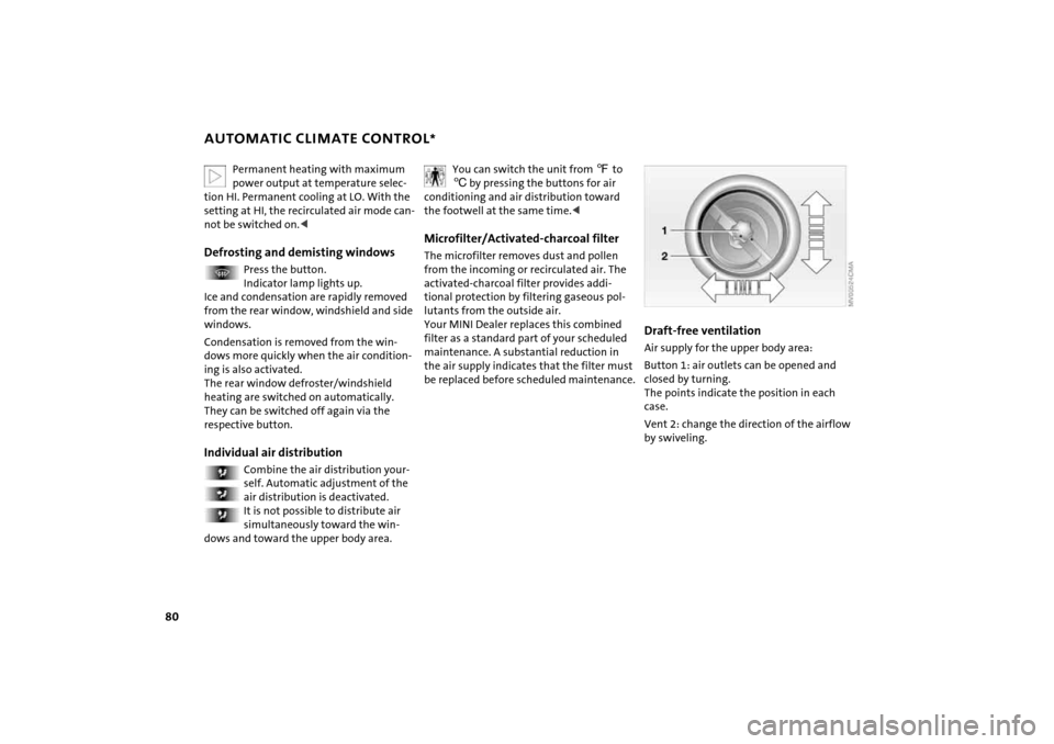
Draft-free ventilation Air supply for the upper body area:Button
1: air outlets can be opened and
closed by turning.
The points indicate the position in each
case.Vent
2: change the direction of the airflow
by swiveling.
Page 86 of 165

84
INTEGRATED UNIVERSAL REMOTE CONTROL
*
4. Simultaneously press the command but
-
ton of the original control device and the
desired memory button
1 on the inte
-
grated universal remote control. The
indicator lamp
2 begins to flash slowly.
Release both buttons when indicator
lamp
2 starts flashing rapidly. If indica
-
tor lamp
2 does not start to flash rapidly
after approx. 15
seconds, change the dis
-
tance between the two devices
5. Repeat steps 3 and 4 to program other
original control devices. The corresponding memory button
1 is
now programmed with the signal of the
original control device.
The system can be operated as soon as the
ignition is switched on.
If the system cannot be operated after repeated attempts at program
-
ming, check whether the original control
device is equipped with an alternating-
code system. You can either check the oper
-
ating instructions of the original control
device for this information, or you can
press and hold down the programmed
memory button
1 of the integrated univer
-
sal remote control. If indicator lamp
2 of
the integrated universal remote control
flashes rapidly for a brief period and then
remains on for approx. two seconds, the
original control device is equipped with an
alternating-code system. In this case, the
memory buttons
1 are programmed as
described for an alternating-code control
device.<
Alternating-code control deviceYou will need to refer to the operating
instructions of the system in question in
order to program the integrated universal
remote control. Read through the operat
-
ing instructions for information on syn
-
chronization.
Observe the following additional instruc
-
tions when you program an alternating-
code control device:
You will find programming easier if you have the assistance of a second
person.<
1. Park your vehicle within range of the
radio-remote-controlled device2. Program the integrated universal
remote control as described above in the
section on fixed-code programming3. Locate the button on the receiver of the
target device, for example on the upper
part of the drive
4. Press the button on the receiver of the
target device. Once you have completed
step
4, you have approx. 30 seconds to
complete step
5
5. Press the programmed memory
button
1 of the integrated universal
remote control three times.
The corresponding memory button
1 is
now programmed with the signal of the
original control device.
Consult your MINI Dealer if you have any questions.<
Deleting memory buttons It is not possible to delete individual mem
-
ory buttons
1. To delete all three memory
buttons
1 at the same time, however, per
-
form the following steps:Press and hold both outer buttons
1 of the
integrated universal remote control for
approx. 20 seconds until indicator lamp
2
flashes.
Page 113 of 165
111
OVERVIEW REPAIRSOPERATIONCONTROLS DATA INDEX
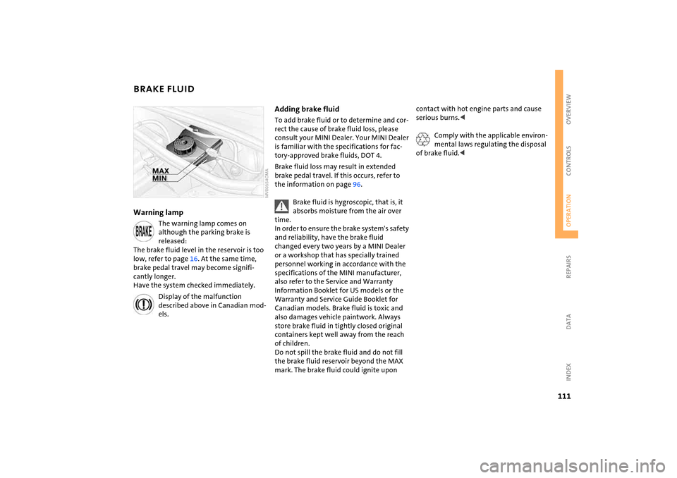
BRAKE FLUIDWarning lamp
The warning lamp comes on although the parking brake is
released:
The brake fluid level in the reservoir is too
low, refer to page
16. At the same time,
brake pedal travel may become signifi
-
cantly longer.
Have the system checked immediately.
Display of the malfunction described above in Canadian mod
-
els.
Adding brake fluid To add brake fluid or to determine and cor
-
rect the cause of brake fluid loss, please
consult your MINI Dealer. Your MINI Dealer
is familiar with the specifications for fac
-
tory-approved brake fluids,
DOT
4.
Brake fluid loss may result in extended
brake pedal travel. If this occurs, refer to
the information on page
96.
Brake fluid is hygroscopic, that is, it absorbs moisture from the air over
time.
In order to ensure the brake system's safety
and reliability, have the brake fluid
changed every two years by a MINI Dealer
or a workshop that has specially trained
personnel working in accordance with the
specifications of the MINI manufacturer,
also refer to the Service and Warranty
Information Booklet for US
models or the
Warranty and Service Guide Booklet for
Canadian models. Brake fluid is toxic and
also damages vehicle paintwork. Always
store brake fluid in tightly closed original
containers kept well away from the reach
of children.
Do not spill the brake fluid and do not fill
the brake fluid reservoir beyond the MAX
mark. The brake fluid could ignite upon
contact with hot engine parts and cause
serious burns.<
Comply with the applicable environ
-
mental laws regulating the disposal
of brake fluid.<
Page 114 of 165

112
MINI MAINTENANCE SYSTEMThe MINI maintenance system helps main
-
tain your vehicle's road safety and opera
-
tional safety. Please bear in mind that regular mainte
-
nance is not only necessary for the safety of
your vehicle, but also plays a significant
role in maintaining the resale value of the
vehicle.
Service interval displayWhile conventional systems specify main
-
tenance according to fixed distances
driven, the MINI Maintenance System takes
account of the operating conditions of the
vehicle, for distances can be driven in many
different ways:
60,000
miles
/ 100,000
km short distance
operation can not be equated with
60,000
miles
/ 100,000
km long distance
operation from a maintenance standpoint.
The condition-based MINI Maintenance
System includes the Engine Oil Service and
Inspections I and II.Determining the maintenance intervals
according to the actual use of the vehicle
covers every kind of operating situation.
People who drive very little, i.e. much less
than 6,000
miles
/ 10,000
km per year,
should have the engine oil changed at least
every 2 years since oil deteriorates over
time, regardless of use.
For more information on the service inter
-
val display, refer to page
65.
Service and Warranty Information
Booklet for US models, Warranty and
Service Guide Booklet for Canadian
models For additional information on maintenance
intervals and procedures, please refer to
the Service and Warranty Information
Booklet for US
models or the Warranty and
Service Guide Booklet for Canadian models.
As a precaution against rust, it is advisable
to have the body checked for damage from
rocks or gravel at the same time, depending
upon operating conditions.
The manufacturer of your MINI rec
-
ommends having maintenance and
repair work carried out only by a MINI
Dealer or a workshop that has specially
trained personnel working in accordance
with the specifications of the MINI manu
-
facturer.
Make sure that maintenance work is con
-
firmed with an entry in the Service and
Warranty Information Booklet for
US
models or the Warranty and Service
Guide Booklet for Canadian models. These
entries are your proof that the vehicle has
received regular maintenance.<
Page 129 of 165

127
OVERVIEW REPAIRSOPERATION CONTROLS DATA INDEX
SPACE-SAVER SPARE TIRE
*
CHANGING TIRES
9.
Pull out the space-saver spare tire towards the rear underneath the vehi
-
cle
10. Position the space-saver spare tire with
the valve facing upwards11. Unscrew the valve extension from the
valve of the space-saver spare tire12. Unscrew the dust cap from the exten
-
sion and place it on the valve of the
space-saver spare tire.Due to its different dimensions, the damaged wheel cannot be placed in
the recess for the space-saver spare tire.<
Driving with the space-saver spare tireDrive cautiously. Do not exceed a speed of
50 mph
/ 80
km/h.
You must expect changes in vehicle han
-
dling such as lower track stability during
braking, longer braking distances and
changes in self-steering properties when
close to the handling limit. These effects
are more pronounced when driving with
winter tires.
Only one space-saver spare tire may be mounted at one time. Reinstall a
wheel and tire of the original size as soon
as possible.
soon as possible and have the new wheel/
tire assembly balanced.<
Additional safety measures in the event of a tire change:
Change the tire only on a level, firm surface
which is not slippery.
The vehicle or the jack could slip sideways
on soft or slippery support surfaces, such as
snow, ice, flagstones, etc..
Do not use a wooden block or similar object
as a support base for the jack, as this would
prevent it from extending to its full support
height and reduce its load-carrying capac
-
ity.
Do not lie under the vehicle or start the
engine when the vehicle is supported by
the jack – risk of fatal injury.
125
.<
1. For vehicles with a space-saver spare
tire:
Place the folding chock behind the front
wheel on the other side of the vehicle;
on downward inclines, place it in front of
this wheel. If the wheel is changed on a
surface with a more severe slope, take
additional precautions to secure the
vehicle from rolling
2. Loosen the lug bolts by a half turn.
Page 151 of 165
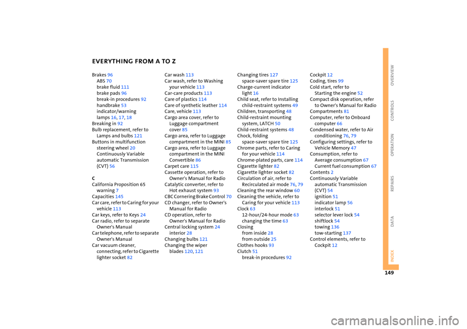
EVERYTHING FROM A TO Z
149
OVERVIEW REPAIRS OPERATION CONTROLS DATA INDEX
Brakes
96
ABS
70
brake fluid
111
brake pads
96
break-in procedures
92
handbrake
53
indicator/warning
lamps
16, 17, 18
Breaking in
92
Bulb replacement, refer to
Lamps and bulbs
121
Buttons in multifunction
steering wheel
20
Continuously Variable
automatic Transmission
(CVT)
56
C California Proposition 65
warning
7
Capacities
145
Car care, refer to Caring for your
vehicle
113
Car keys, refer to Keys
24
Car radio, refer to separate Owner's Manual
Car telephone, refer to separate Owner's Manual
Car vacuum cleaner,
connecting, refer to Cigarette
lighter socket
82
Car wash
113
Car wash, refer to Washing
your vehicle
113
Car-care products
113
Care of plastics
114
Care of synthetic leather
114
Care, vehicle
113
Cargo area cover, refer to
Luggage compartment
cover
85
Cargo area, refer to Luggage
compartment in the MINI
85
Cargo area, refer to Luggage
compartment in the MINI
Convertible
86
Carpet care
115
Cassette operation, refer to
Owner's Manual for Radio
Catalytic converter, refer to
Hot exhaust system
93
CBC Cornering Brake Control
70
CD changer, refer to Owner's Manual for Radio
CD operation, refer to
Owner's Manual for Radio
Central locking system
24
interior
28
Changing bulbs
121
Changing the wiper
blades
120
, 121
Changing tires
127
space-saver spare tire
125
Charge-current indicator
light
16
Child seat, refer to Installing
child-restraint systems
49
Children, transporting
48
Child-restraint mounting
system, LATCH
50
Child-restraint systems
48
Chock, folding
space-saver spare tire
125
Chrome parts, refer to Caring
for your vehicle
114
Chrome-plated parts, care
114
Cigarette lighter
82
Cigarette lighter socket
82
Circulation of air, refer to
Recirculated air mode
76, 79
Cleaning the rear window
60
Cleaning the vehicle, refer to
Caring for your vehicle
113
Clock
63
12-hour/24-hour mode
63
changing the time
63
Closing
from inside
28
from outside
25
Clothes hooks
93
Clutch
51
break-in procedures
92
Cockpit
12
Coding, tires
99
Cold start, refer to
Starting the engine
52
Compact disk operation, refer to Owner's Manual for Radio
Compartments
81
Computer, refer to Onboard
computer
66
Condensed water, refer to Air
conditioning
76, 79
Configuring settings, refer to
Vehicle Memory
47
Consumption, refer to
Average consumption
67
Current fuel consumption
67
Contents
2
Continuously Variable
automatic Transmission
(CVT)
54
ignition
51
indicator lamp
56
interlock
51
selector lever lock
54
shiftlock
54
towing
136
tow-starting
137
Control elements, refer to
Cockpit
12