turn signal MINI Hardtop 2 Door 2005 Owner's Manual
[x] Cancel search | Manufacturer: MINI, Model Year: 2005, Model line: Hardtop 2 Door, Model: MINI Hardtop 2 Door 2005Pages: 165, PDF Size: 2.32 MB
Page 14 of 165
12
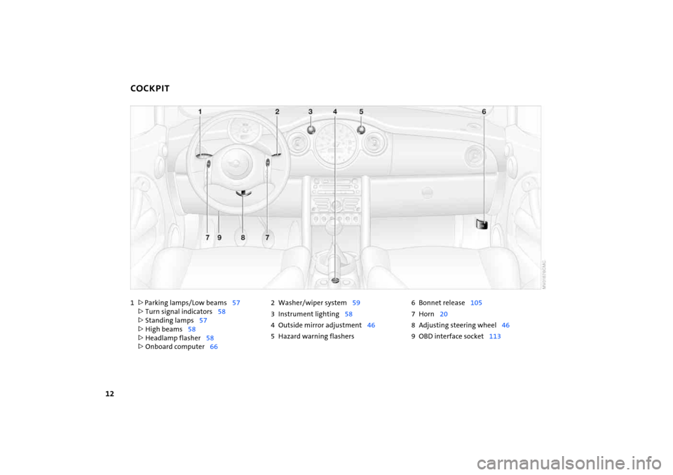
1>
Parking lamps/Low beams
57
>Turn signal indicators
58
>Standing lamps
57
>High beams
58
>Headlamp flasher
58
>Onboard computer
66
2Washer/wiper system
59
3 Instrument lighting
58
4 Outside mirror adjustment
46
5 Hazard warning flashers
6 Bonnet release
105
7Horn
20
8 Adjusting steering wheel
46
9OBD interface socket
113
COCKPIT
Page 21 of 165
19
OVERVIEW REPAIRS OPERATION CONTROLS DATA INDEX
INDICATOR AND WARNING LAMPSYellow: for your information
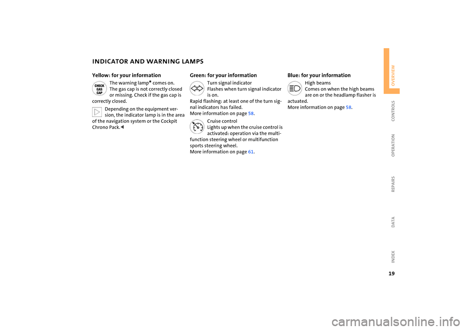
The warning lamp
* comes on.
The gas cap is not correctly closed
or missing. Check if the gas cap is
correctly closed.Depending on the equipment ver
-
sion, the indicator lamp is in the area
of the navigation system or the Cockpit
Chrono Pack.<
Green: for your information
Turn signal indicator
Flashes when turn signal indicator
is on.
Rapid flashing: at least one of the turn sig
-
nal indicators has failed.
More information on page
58.
Cruise control
Lights up when the cruise control is
activated: operation via the multi
-
function steering wheel or multifunction
sports steering wheel.
More information on page
61.
Blue: for your information
High beams
Comes on when the high beams
are on or the headlamp flasher is
actuated.
More information on page
58.
Page 28 of 165
26
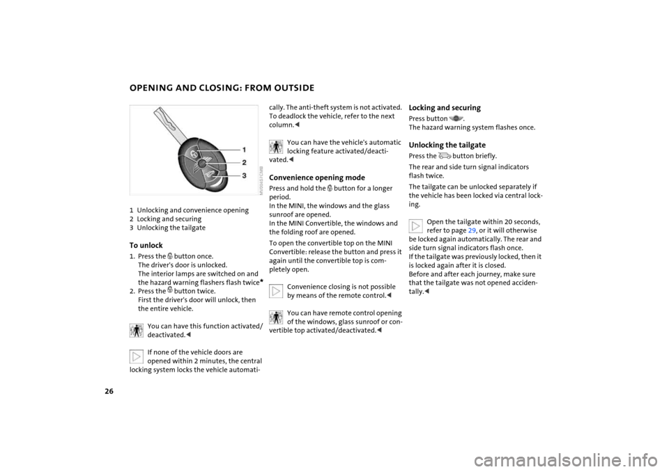
OPENING AND CLOSING: FROM OUTSIDE 1Unlocking and convenience opening2 Locking and securing3 Unlocking the tailgateTo unlock1. Press the
button once.
The driver's door is unlocked.
The interior lamps are switched on and
the hazard warning flashers flash twice
*
2. Press the
button twice.
First the driver's door will unlock, then
the entire vehicle.
You can have this function activated/deactivated.
locking system locks the vehicle automati
-
cally. The anti-theft system is not activated.
To deadlock the vehicle, refer to the next
column.<
You can have the vehicle's automatic locking feature activated/deacti
-
vated.
period.
In the MINI, the windows and the glass
sunroof are opened.
In the MINI Convertible, the windows and
the folding roof are opened.To open the convertible top on the MINI
Convertible: release the button and press it
again until the convertible top is com
-
pletely open.
Convenience closing is not possible by means of the remote control.
vertible top activated/deactivated.<
Locking and securingPress button
.
The hazard warning system flashes once.Unlocking the tailgate Press the
button briefly.
The rear and side turn signal indicators
flash twice.The tailgate can be unlocked separately if
the vehicle has been locked via central lock
-
ing.
Open the tailgate within 20
seconds,
refer to page
29, or it will otherwise
be locked again automatically. The rear and
side turn signal indicators flash once.
If the tailgate was previously locked, then it
is locked again after it is closed.
Before and after each journey, make sure
that the tailgate was not opened acciden
-
tally.<
Page 59 of 165

57
OVERVIEW REPAIRS OPERATIONCONTROLS DATA INDEX
PARKING LAMPS/LOW BEAMS Switching on the parking lamps Turn to the first position.
The front, rear and side vehicle lighting is
switched on.
Standing lamps on one side, refer to next
column.Switching on the low beamsTurn to the second position.
With the low beams on and with the igni
-
tion switched off, only the parking lamps
will remain on.
'Follow me home' lampsIf you activate the headlamp flasher after
having switched off the engine and the
lights, the low beams will stay lit for a pre
-
set period of time.
You can have this function pro
-
grammed.<
Switching on the standing lamps For parking, you can activate lights on one
side of the vehicle. Observe local laws.In ignition key position
0:
Move the lever to the adequate turn signal
indicator position.
The standing lamps discharge the battery. Avoid using them for longer
periods of time; otherwise, you may not be
able to start the engine.<
'Lights on' warning If the lights have not been switched off and
the ignition key is in position
0, an acoustic
signal sounds for a few seconds when you
open the driver's door to remind you that
the lights have not been switched off.
Daytime driving lamps* If convenient, the light switch can be left in
position
0 or 1.
The low beams switch on automatically in
ignition key position 2 or higher.
The exterior lamps go out when the igni
-
tion is switched off and the light switch is
set to position 0. In position 1, the parking
lamps are automatically switched on.
The dynamic headlamp range con
-
trol for xenon lamps only operates
with the light switch in position
1 or 2.<
You can have the daytime driving lamp function activated/deacti
-
vated.<
Page 60 of 165

58
SIGNAL/HEADLAMP FLASHER
INSTRUMENT LIGHTING
FOG LAMPS
1Turn signal indicators 2 High beams/Headlamp flasher To signal brieflyGently push the lever up to the point of
resistance and hold it there, if necessary.
The lever returns to its center position once
it is released.
The indicator lamp flashes and the relay clicks faster than normal: a turn
signal indicator has failed.<
To control the instrument lighting, press the button.To increase the illumination intensityKeep the button pressed until the desired
brightness is reached.To decrease the illumination intensityPress the button briefly.
With each brief pressing of the button, the
illumination intensity is reduced in steps.
When the parking lamps/low beams are switched on:
Briefly press the switch upwards or down
-
wards.Briefly press once again to switch off.Fog lamps*
The parking lamps or low beams must be switched on. The green
indicator lamp lights up.
The fog lamps are switched on.Rear fog lamp*
The low beams must be switched on. The yellow indicator lamp
lights up. The rear fog lamp is
switched on.
Observe all legal regulations concerning
the use of fog lamps.
Page 68 of 165
66
ONBOARD COMPUTER
*
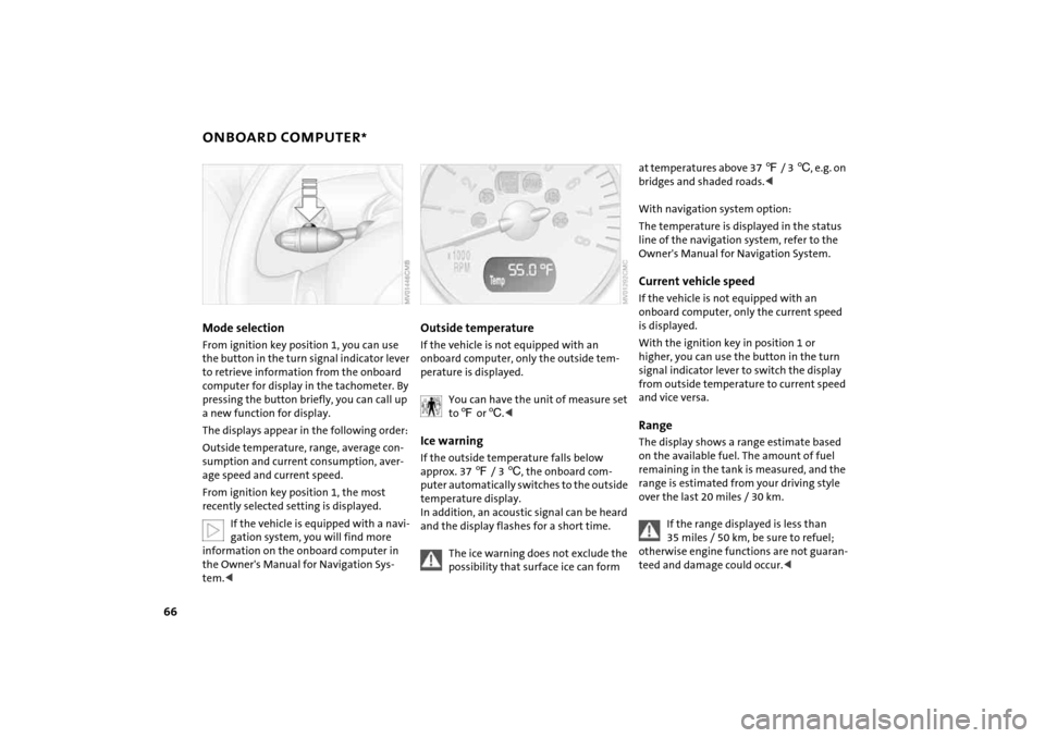
Mode selectionFrom ignition key position
1, you can use
the button in the turn signal indicator lever
to retrieve information from the onboard
computer for display in the tachometer. By
pressing the button briefly, you can call up
a new function for display.
The displays appear in the following order:Outside temperature, range, average con
-
sumption and current consumption, aver
-
age speed and current speed.From ignition key position
1, the most
recently selected setting is displayed.
If the vehicle is equipped with a navi
-
gation system, you will find more
information on the onboard computer in
the Owner's Manual for Navigation Sys
-
tem.<
Outside temperature If the vehicle is not equipped with an
onboard computer, only the outside tem
-
perature is displayed.
You can have the unit of measure set to 7 or
6.<
Ice warning If the outside temperature falls below
approx. 37
7 / 3
6, the onboard com
-
puter automatically switches to the outside
temperature display.
In addition, an acoustic signal can be heard
and the display flashes for a short time.
The ice warning does not exclude the possibility that surface ice can form
at temperatures above 37
7 / 3
6, e.g. on
bridges and shaded roads.<
With navigation system option:The temperature is displayed in the status
line of the navigation system, refer to the
Owner's Manual for Navigation System.Current vehicle speedIf the vehicle is not equipped with an
onboard computer, only the current speed
is displayed.With the ignition key in position
1 or
higher, you can use the button in the turn
signal indicator lever to switch the display
from outside temperature to current speed
and vice versa.
RangeThe display shows a range estimate based
on the available fuel. The amount of fuel
remaining in the tank is measured, and the
range is estimated from your driving style
over the last 20
miles
/ 30 km.
If the range displayed is less than 35 miles
/ 50 km, be sure to refuel;
otherwise engine functions are not guaran
-
teed and damage could occur.<
Page 69 of 165
67
OVERVIEW REPAIRS OPERATIONCONTROLS DATA INDEX
ONBOARD COMPUTER
*
Average speed, average fuel
consumption Press the button in the turn signal indicator
lever for a longer period.The displayed average values for speed and
consumption are recalculated.Any time spent with the vehicle stationary
and the engine shut off is ignored for the
calculation.
If the vehicle is equipped with a navi
-
gation system, the displays are
shown in the area of the navigation sys
-
tem.<
You can have a different unit of mea
-
sure set.<
Current fuel consumptionThe current consumption value is calcu
-
lated and displayed on the basis of your
driving style.
You can have a different unit of mea
-
sure set.<
Page 124 of 165
122
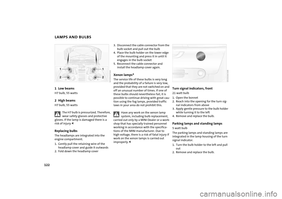
LAMPS AND BULBS1 Low beams
H7 bulb, 55
watts
2 High beams
H7 bulb, 55
watts
The H7 bulb is pressurized. Therefore, wear safety glasses and protective
gloves. If the lamp is damaged there is a
risk of injury.<
Replacing bulbs The headlamps are integrated into the
engine compartment.1. Gently pull the retaining wire of the
headlamp cover and guide it outwards2. Fold down the headlamp cover
3. Disconnect the cable connector from the
bulb socket and pull out the bulb4. Place the bulb holder on the lower edge
of the mounting and press it in until it
engages in the bulb socket 5. Reconnect the cable connector and
install the headlamp cover again.Xenon lamps* The service life of these bulbs is very long
and the probability of a failure is very low,
provided that they are not switched on and
off an unusual number of times. If one of
these bulbs should nevertheless fail, it is
possible to continue driving with great cau
-
tion using the fog lamps, provided traffic
laws in your area do not prohibit this.
Have any work on the xenon lamp system, including bulb replacement,
carried out only by a MINI Dealer or a work
-
shop that has specially trained personnel
working in accordance with the specifica
-
tions of the MINI manufacturer. Due to
high voltage, there is a risk of fatal injury if
work on the xenon lamps is carried out
improperly.<
Turn signal indicators, front 21 watt bulb
1. Open the bonnet2. Reach into the opening for the turn sig
-
nal indicators from above
3. Apply gentle pressure to the bulb holder
while turning it to the left4. Remove and replace the bulb.Parking lamps and standing lamps 5 watt bulb The parking lamps and standing lamps are
integrated in the lamp housing of the turn
signal indicator.1. Turn the bulb holder to the left and pull
out2. Remove and replace the bulb.
Page 125 of 165
123
OVERVIEW REPAIRSOPERATION CONTROLS DATA INDEX
LAMPS AND BULBSSide turn signal indicators 5 watt bulb1. Slide the lamp toward the rear of the
vehicle and remove2. Remove and replace the bulb.
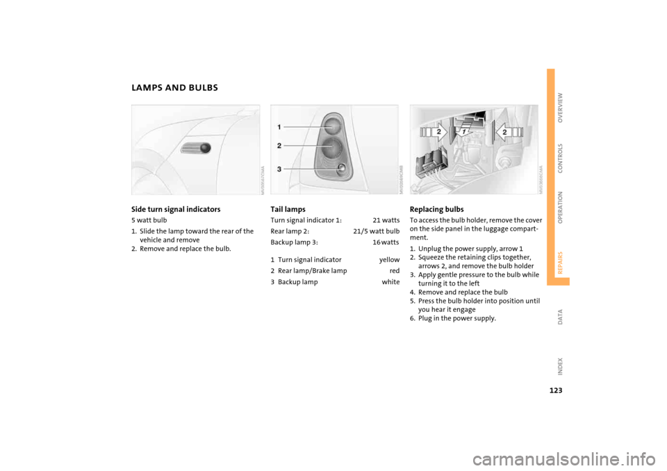
Tail lampsTurn signal indicator 1: 21
watts
Rear lamp 2: 21/5 watt bulbBackup lamp 3: 16 watts 1 Turn signal indicator yellow2 Rear lamp/Brake lamp red3 Backup lamp white
Replacing bulbs To access the bulb holder, remove the cover
on the side panel in the luggage compart
-
ment.1. Unplug the power supply, arrow
1
2. Squeeze the retaining clips together,
arrows
2, and remove the bulb holder
3. Apply gentle pressure to the bulb while
turning it to the left4. Remove and replace the bulb5. Press the bulb holder into position until
you hear it engage6. Plug in the power supply.
Page 152 of 165
EVERYTHING FROM A TO Z
150
Convenience operation
convertible top
37
from outside
26, 27
glass sunroof, electric
33
windows
31
Convertible top
35
care
115
convenience operation
37
electrical malfunction
37
emergency closing
37
malfunction
37
Coolant
110
indicator lamp
16
level
110
temperature gauge
64
Coolant temperature gauge
64
Cooling system, refer to
Capacities
145
Cooling, refer to Air
conditioning
76, 79
Copyright
2
Cornering Brake Control
(CBC)
70
warning lamp
17
Correct tires
99
Cosmetic mirror, refer to
Illuminated vanity mirror
47
Cruise control
61
buttons in the steering
wheel
20, 21
indicator lamp
19
Cup holders, refer to Beverage
holders
81
Curb weight, refer to
Weights
143
, 144
Current fuel consumption
67
setting units
67
Cylinders, refer to Engine
data
140
D Daily odometer, refer to Trip
odometer
63
Dashboard lighting, refer to
Instrument lighting
58
Dashboard, refer to Cockpit
12
Data
capacities
145
dimensions
141
engine
140
technical
140
weights
143
Date of the Owner's Manual
7
Daytime driving lamps
57
Deep water, refer to Driving
through water
93
Defrost setting, refer to
Defrosting and demisting
windows
80
Defrosting and demisting
windows
automatic climate control
80
Defrosting windows
80
air conditioning system
76
automatic climate control
79
Defrosting windshield, refer to
Defrosting and demisting
windows
80
Demisting windows
80
Digital clock
63
Dimensions
141
, 142
Dimming interior rearview
mirror
47
Dipstick, engine oil
108
Directional turn signal,
refer to Turn signal
indicators
58
Disc brakes
96
Displacement, refer to Engine
data
140
Display elements
13
with navigation system or
Cockpit Chrono Pack
14
Display lighting, refer to
Instrument lighting
58
Disposal
engine oil
109
vehicle battery
132
Distance covered, refer to
Odometer
63
Distance warning, refer to Park
Distance Control (PDC)
74
Door keys
24
Door lock
27
Doors, locking and unlocking
acknowledgment
signals
26, 27
from inside
28
from outside
26
DOT quality grades
99
Draft-free ventilation
77, 80
Drink holders, refer to Beverage
holders
81
Driving lamps, refer to Parking
lamps/Low beams
57
Driving notes
93
Driving stability control
systems
68, 69
Dry air, refer to Air
conditioning
76, 79
Drying air,
refer to Air
conditioning
76, 79
DSC Dynamic Stability
Control
69
indicator lamp
17
Dynamic Stability
Control (DSC)
69
indicator lamp
17
E Easy entry to the rear
44
EBD Electronic Brake Force
Distribution
70