ignition MINI Hardtop 2 Door 2006 Owner's Manual
[x] Cancel search | Manufacturer: MINI, Model Year: 2006, Model line: Hardtop 2 Door, Model: MINI Hardtop 2 Door 2006Pages: 168, PDF Size: 2.22 MB
Page 5 of 168
3
OVERVIEW REPAIRS OPERATION CONTROLS DATA INDEX
Driving:
Ignition lock53
Starting the engine53
Switching off the engine54
Parking brake54
Manual transmission55
Automatic transmission with
Steptronic56
Parking lamps/Low beams59
Turn signal indicator/Headlamp
flasher60
Instrument lighting61
Fog lamps61
Interior lamps61
Washer/wiper system62
Washer fluid63
Cruise control64
Everything under control:
Odometer66
Clock66
Fuel gauge66
Coolant temperature gauge67
Tachometer68
Service interval display68
Onboard computer69Technology for safety and driving
convenience:
Driving stability control systems71
Flat Tire Monitor73
Airbags75
Park Distance Control (PDC)77
Controlling the climate for pleasant
driving:
Air conditioning system78
Automatic climate control81
Interior conveniences:
Glove compartment84
Center armrest84
Drinks holders, ashtray85
Cigarette lighter, 12 V power supply85
Integrated universal remote control86
Loading and transporting cargo:
Luggage compartment in the MINI88
Luggage compartment in the MINI
Convertible89
Loading cargo90
Roof-mounted luggage rack93OPERATION, CARE, MAINTENANCE
Special operating instructions:
Break-in procedures96
General driving notes96
Refueling99
Wheels and tires:
Tire inflation pressure101
Tire coding105
Tire condition106
Run Flat tires108
New wheels and tires109
Snow chains110
Page 18 of 168
16
INDICATOR AND WARNING LAMPS
Technology that monitors itself
The system runs a check on the indicator
and warning lamps marked by
+ when you
turn the key in the ignition lock. They each
light up once for different periods of time.
If a malfunction should occur in one of
these systems, the corresponding lamp
does not go out after the engine is started
or it lights up while the vehicle is moving.
You will see below the correct way to react
to this.
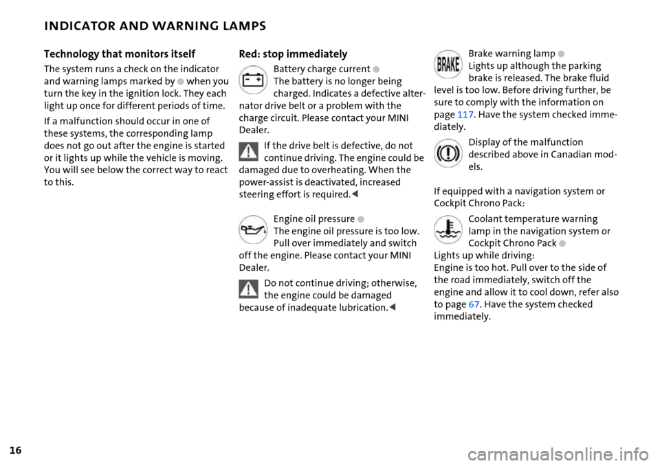
Red: stop immediately
Battery charge current+
The battery is no longer being
charged. Indicates a defective alter-
nator drive belt or a problem with the
charge circuit. Please contact your MINI
Dealer.
If the drive belt is defective, do not
continue driving. The engine could be
damaged due to overheating. When the
power-assist is deactivated, increased
steering effort is required.<
Engine oil pressure
+
The engine oil pressure is too low.
Pull over immediately and switch
off the engine. Please contact your MINI
Dealer.
Do not continue driving; otherwise,
the engine could be damaged
because of inadequate lubrication.<
Brake warning lamp+
Lights up although the parking
brake is released. The brake fluid
level is too low. Before driving further, be
sure to comply with the information on
page117. Have the system checked imme-
diately.
Display of the malfunction
described above in Canadian mod-
els.
If equipped with a navigation system or
Cockpit Chrono Pack:
Coolant temperature warning
lamp in the navigation system or
Cockpit Chrono Pack
+
Lights up while driving:
Engine is too hot. Pull over to the side of
the road immediately, switch off the
engine and allow it to cool down, refer also
to page67. Have the system checked
immediately.
Page 19 of 168
17
OVERVIEW REPAIRS OPERATION CONTROLS DATA INDEX
INDICATOR AND WARNING LAMPS
Yellow: stop immediately
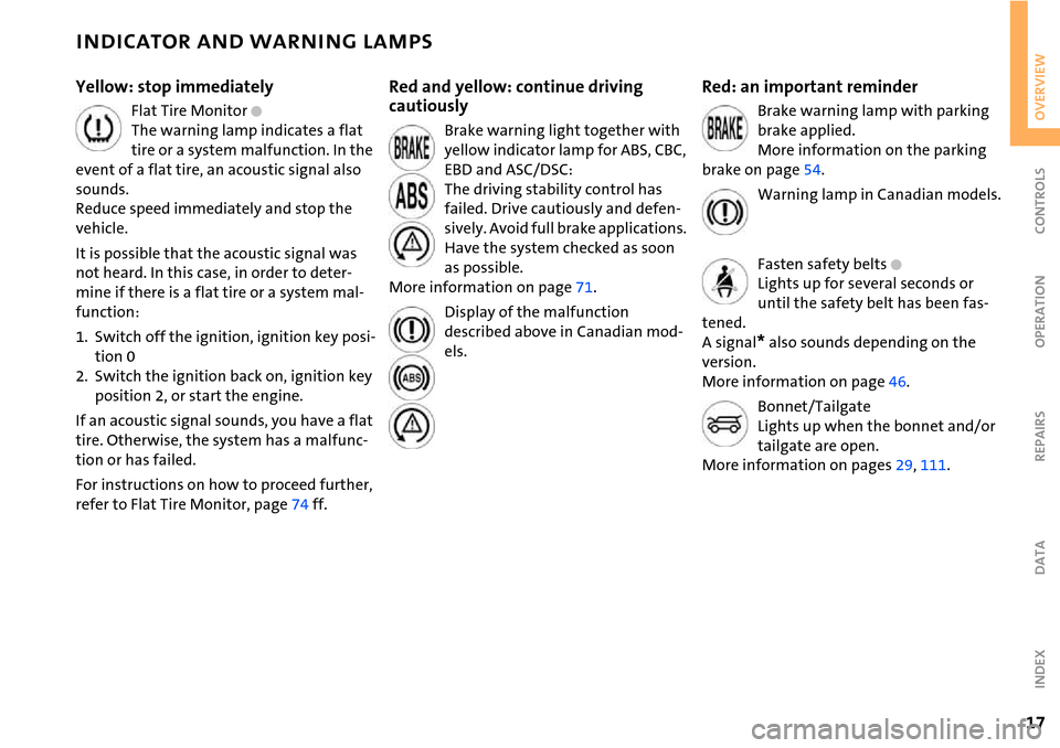
Flat Tire Monitor +
The warning lamp indicates a flat
tire or a system malfunction. In the
event of a flat tire, an acoustic signal also
sounds.
Reduce speed immediately and stop the
vehicle.
It is possible that the acoustic signal was
not heard. In this case, in order to deter-
mine if there is a flat tire or a system mal-
function:
1. Switch off the ignition, ignition key posi-
tion 0
2. Switch the ignition back on, ignition key
position 2, or start the engine.
If an acoustic signal sounds, you have a flat
tire. Otherwise, the system has a malfunc-
tion or has failed.
For instructions on how to proceed further,
refer to Flat Tire Monitor, page74 ff.
Red and yellow: continue driving
cautiously
Brake warning light together with
yellow indicator lamp for ABS, CBC,
EBD and ASC/DSC:
The driving stability control has
failed. Drive cautiously and defen-
sively. Avoid full brake applications.
Have the system checked as soon
as possible.
More information on page71.
Display of the malfunction
described above in Canadian mod-
els.
Red: an important reminder
Brake warning lamp with parking
brake applied.
More information on the parking
brake on page54.
Warning lamp in Canadian models.
Fasten safety belts
+
Lights up for several seconds or
until the safety belt has been fas-
tened.
A signal
* also sounds depending on the
version.
More information on page46.
Bonnet/Tailgate
Lights up when the bonnet and/or
tailgate are open.
More information on pages29, 111.
Page 26 of 168

24
KEYS CENTRAL LOCKING SYSTEM
Depending on your vehicle's equipment
vesion, you will have received the following
keys:
1 Master keys with remote control
2 Spare key
Master keys with remote control
In every master key with remote control,
there is an extended-life battery as a power
supply that is charged automatically in the
ignition lock as you drive.
You should therefore use each master key at
least twice a year to maintain the charge sta-
tus.
Depending on which master key the vehicle
detects when it is unlocked, different settings
will be called up and executed inside the vehi-
cle, refer to Vehicle Memory on page49.
Spare key
For keeping in a safe place, e.g. in your wal-
let. This key is not intended for constant
use.
The concept
The central locking system is ready for
operation whenever the driver's door is
closed. The doors, the tailgate and the fuel
filler door are unlocked or locked.
The central locking system locks or unlocks
your vehicle:
>When operated from the outside via the
remote control as well as via the door
lock
>When operated from the inside via a
switch
>The vehicle is unlocked automatically
when the ignition key is pulled out of the
ignition switch.
If operated from outside, the anti-theft sys-
tem is activated at the same time. This pre-
vents the doors from being unlocked via
safety lock buttons or door handles.
In the event of a sufficiently severe acci-
dent, the central locking system unlocks
automatically. The hazard warning flashers
and interior lamps are also switched on.
Page 32 of 168
30
TAILGATE
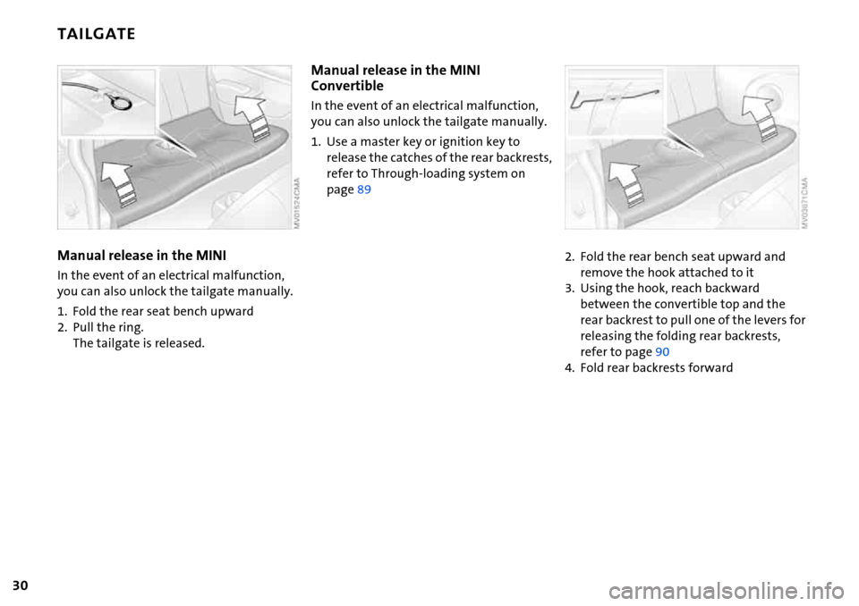
Manual release in the MINI
In the event of an electrical malfunction,
you can also unlock the tailgate manually.
1. Fold the rear seat bench upward
2. Pull the ring.
The tailgate is released.
Manual release in the MINI
Convertible
In the event of an electrical malfunction,
you can also unlock the tailgate manually.
1. Use a master key or ignition key to
release the catches of the rear backrests,
refer to Through-loading system on
page89
2. Fold the rear bench seat upward and
remove the hook attached to it
3. Using the hook, reach backward
between the convertible top and the
rear backrest to pull one of the levers for
releasing the folding rear backrests,
refer to page90
4. Fold rear backrests forward
Page 33 of 168
31
OVERVIEW REPAIRS OPERATIONCONTROLS DATA INDEX
TAILGATE ELECTRIC POWER WINDOWS
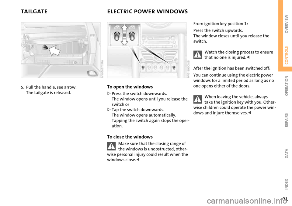
5. Pull the handle, see arrow.
The tailgate is released.To open the windows
>Press the switch downwards.
The window opens until you release the
switch or
>Tap the switch downwards.
The window opens automatically.
Tapping the switch again stops the oper-
ation.
To close the windows
Make sure that the closing range of
the windows is unobstructed, other-
wise personal injury could result when the
windows close.<
From ignition key position 1:
Press the switch upwards.
The window closes until you release the
switch.
Watch the closing process to ensure
that no one is injured.<
After the ignition has been switched off:
You can continue using the electric power
windows for a limited period as long as no
one opens either of the doors.
When leaving the vehicle, always
take the ignition key with you. Other-
wise children could operate the power win-
dows and injure themselves.<
Page 35 of 168
33
OVERVIEW REPAIRS OPERATIONCONTROLS DATA INDEX
GLASS SUNROOF, ELECTRIC*
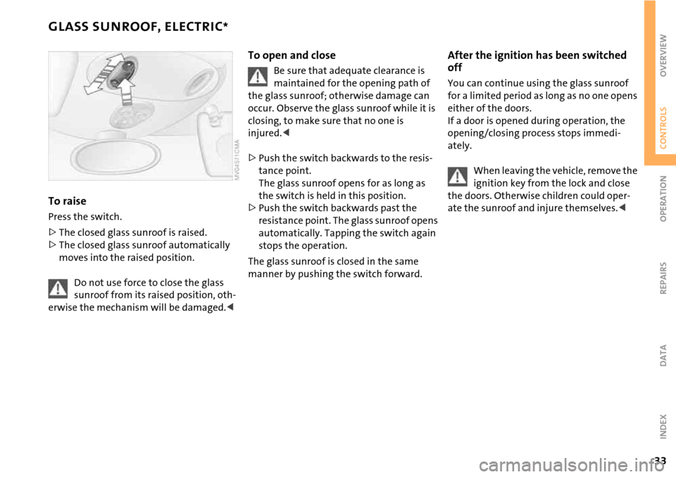
To raise
Press the switch.
>The closed glass sunroof is raised.
>The closed glass sunroof automatically
moves into the raised position.
Do not use force to close the glass
sunroof from its raised position, oth-
erwise the mechanism will be damaged.<
To open and close
Be sure that adequate clearance is
maintained for the opening path of
the glass sunroof; otherwise damage can
occur. Observe the glass sunroof while it is
closing, to make sure that no one is
injured.<
>Push the switch backwards to the resis-
tance point.
The glass sunroof opens for as long as
the switch is held in this position.
>Push the switch backwards past the
resistance point. The glass sunroof opens
automatically. Tapping the switch again
stops the operation.
The glass sunroof is closed in the same
manner by pushing the switch forward.
After the ignition has been switched
off
You can continue using the glass sunroof
for a limited period as long as no one opens
either of the doors.
If a door is opened during operation, the
opening/closing process stops immedi-
ately.
When leaving the vehicle, remove the
ignition key from the lock and close
the doors. Otherwise children could oper-
ate the sunroof and injure themselves.<
Page 39 of 168
37
OVERVIEW REPAIRS OPERATIONCONTROLS DATA INDEX
CONVERTIBLE TOP WITH INTEGRATED SLIDING SUNROOF
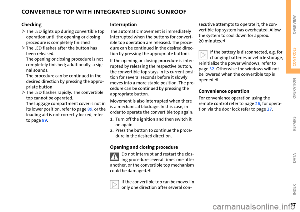
Checking
>The LED lights up during convertible top
operation until the opening or closing
procedure is completely finished
>The LED flashes after the button has
been released.
The opening or closing procedure is not
completely finished; additionally, a sig-
nal sounds.
The procedure can be continued in the
desired direction by pressing the appro-
priate button
>The LED flashes rapidly. The convertible
top cannot be operated.
The luggage compartment cover is not in
its lower position, refer to page89, or the
loading aid is not correctly locked, refer
to page89.
Interruption
The automatic movement is immediately
interrupted when the buttons for convert-
ible top operation are released. The proce-
dure can be continued in the desired direc-
tion by pressing the appropriate buttons.
If the opening or closing procedure is inter-
rupted by releasing the respective button,
the convertible top stays in its current posi-
tion for several seconds before it slowly
moves into a more stable position. The pro-
cedure can be continued by pressing the
appropriate button.
Movement is also interrupted when there
is a mechanical blockage. In this case, in
order to operate the convertible top again:
1. Turn off the ignition and then switch it
on again
2. Press the button to continue the proce-
dure in the desired direction.
Opening and closing procedure
Do not interrupt and restart the clos-
ing procedure several times one after
another, or the convertible top mechanism
could be damaged.<
If the convertible top can be moved in
only one direction after several con-
secutive attempts to operate it, the con-
vertible top system has overheated. Allow
the system to cool down for approx.
20 minutes.<
If the battery is disconnected, e.g. for
changing batteries or vehicle storage,
reinitialize the power windows, refer to
page32. Otherwise the windows will not
be lowered when the convertible top is
opened.<
Convenience operation
For convenience operation using the
remote control refer to page26, for opera-
tion via the door lock refer to page27.
Page 44 of 168

42
SAFE SEATING POSITION
The ideal seating position can make a vital
contribution to relaxed, relatively fatigue-
free driving. Together with the safety belts
and airbags, the seating position also plays
an important role in providing occupants
with maximum levels of passive safety in
an accident. To ensure that the safety sys-
tems operate with optimal efficiency, we
strongly urge you to observe the instruc-
tions contained in the following section.
For additional information about trans-
porting children safely, refer to page50.
Airbags
Always maintain an adequate dis-
tance between yourself and all of the
airbags. Always hold the steering wheel by
the rim with the hands at the 9 and
3 o'clock positions to keep any chance of
injury to hands or arms to an absolute min-
imum, should the airbag be deployed.
No one and nothing is to come between
the airbags and the seat occupant. Do not
use the front passenger airbag cover as a
storage surface for objects of any kind.
Ensure that the front passenger is correctly
seated, e.g. that no feet or legs are propped
against the dashboard. Otherwise, leg
injury could result if the front passenger
airbag suddenly deployed.
Make sure that passengers do not lean
their heads against the side or head airbag,
as injuries could result if the side airbags
were triggered.<
Even if all these instructions are followed, it
cannot entirely be ruled out that in some
circumstances injury may result from con-
tact with the airbags. In sensitive individu-
als, the ignition and inflation noise may
induce a mild hearing loss that is usually
temporary.
For airbag locations and additional infor-
mation on airbags, refer to page75.
Head restraint
A correctly adjusted head restraint reduces
the risk of injury to the cervical spine in the
event of an accident.
Adjust the head restraint in such a
way that it is centered roughly at ear
level. Otherwise, there is an increased risk
of injury in the event of an accident.<
Safety belt
Fasten your safety belt before each drive.
Airbags are an additional safety device and
work in conjunction with the safety belts,
but do not replace them. Your vehicle is
equipped with four seats, each of which is
provided with a safety belt.
Expectant mothers should always
wear their safety belts, taking care to
position the belt in the pelvic area against
the lower hips, where it will not exert pres-
sure against the abdomen.
Never allow more than one person to wear
a single safety belt. Never allow infants or
small children to ride in a passenger's lap.
Do not route the belt across your neck, or
run it across sharp edges. Be sure that the
belt does not become caught or jammed.
Avoid twisting the belt while routing it
firmly across the hips and shoulder; wear it
as snugly against your body as possible and
do not allow it to rest against hard or frag-
ile objects. Otherwise, the belt in the pelvic
area could slide over the hips in the event
of a frontal impact, leading to abdominal
injury. Avoid wearing bulky clothing and
pull the belt in the upper-body area upward
periodically to retension it. Otherwise, the
restraining effect of the safety belt could
be diminished.<
For information on using the safety belts,
refer to page46.
Page 50 of 168

48
MIRRORS
Exterior mirrors
The front passenger's mirror is more
concave than the driver's mirror. The
objects reflected in the mirror are closer
than they appear. Do not gauge your dis-
tance from following traffic based on what
you see in the mirrors; otherwise there is
an increased risk of an accident.<
Adjusting
1 Button for 4-way adjustment
2 Switch for choosing between the left and
right mirror
3 To fold the mirrors in or out
*
To adjust manually
The mirrors can also be adjusted manually:
Press the edge of the lens.
To fold the mirrors in or out*
Press button 3.
The mirrors can be folded in or out up to a
road speed of approx. 20 mph / 30 km/h.
This can be useful on narrow roads, for
example, or to reset the mirrors to their
correct positions after they have been
folded in.
Automatic heating*
Both mirrors are heated automatically
when the ignition key is in position 2.
Interior rearview mirror
To reduce glare from vehicles behind you
when you are driving at night:
Turn the knob.
Illuminated vanity mirrors
1. Fold down the sun visor
2. Fold up the cover panel.
Sun visors
Can be swung sideways.
An additional sun visor is provided on the
driver's side to better protect the driver
from being blinded.