wheel MINI Hardtop 2 Door 2006 Owner's Manual
[x] Cancel search | Manufacturer: MINI, Model Year: 2006, Model line: Hardtop 2 Door, Model: MINI Hardtop 2 Door 2006Pages: 168, PDF Size: 2.22 MB
Page 4 of 168
CONTENTS
2
© 2005 Bayerische Motoren Werke
Aktiengesellschaft
Munich, Germany
Reprinting, including excerpts, only with the
written consent of BMW AG, Munich.
Order No. 01 41 0 159 801
US-English VIII/05
Printed in Germany
Printed on environmentally friendly paper,
bleached without chlorine, suitable for recycling.
NOTES
About this Owner's Manual6
Additional sources of information6
Symbols used6
Your individual vehicle6
Editorial notice7
For your own safety7
Symbol on vehicle parts8
Service and warranty8
Reporting safety defects9
OVERVIEW
Cockpit12
Display elements13
Display elements with navigation system
or Cockpit Chrono Pack14
Indicator and warning lamps16
Multifunction steering wheel20
CONTROLS
Opening and closing:
Keys24
Central locking system24
Opening and closing: from outside25
Opening and closing: from inside28
Tailgate29
Electric power windows31
Glass sunroof, electric33
Roller sun blind34
Convertible top with integrated sliding
sunroof35
Wind deflector40
Adjustments:
Safe seating position42
Seat adjustment43
Head restraints44
Entry to the rear45
Safety belts46
Seat heating47
Steering wheel47
Mirrors48
Vehicle Memory49
Transporting children safely50
Page 5 of 168
3
OVERVIEW REPAIRS OPERATION CONTROLS DATA INDEX
Driving:
Ignition lock53
Starting the engine53
Switching off the engine54
Parking brake54
Manual transmission55
Automatic transmission with
Steptronic56
Parking lamps/Low beams59
Turn signal indicator/Headlamp
flasher60
Instrument lighting61
Fog lamps61
Interior lamps61
Washer/wiper system62
Washer fluid63
Cruise control64
Everything under control:
Odometer66
Clock66
Fuel gauge66
Coolant temperature gauge67
Tachometer68
Service interval display68
Onboard computer69Technology for safety and driving
convenience:
Driving stability control systems71
Flat Tire Monitor73
Airbags75
Park Distance Control (PDC)77
Controlling the climate for pleasant
driving:
Air conditioning system78
Automatic climate control81
Interior conveniences:
Glove compartment84
Center armrest84
Drinks holders, ashtray85
Cigarette lighter, 12 V power supply85
Integrated universal remote control86
Loading and transporting cargo:
Luggage compartment in the MINI88
Luggage compartment in the MINI
Convertible89
Loading cargo90
Roof-mounted luggage rack93OPERATION, CARE, MAINTENANCE
Special operating instructions:
Break-in procedures96
General driving notes96
Refueling99
Wheels and tires:
Tire inflation pressure101
Tire coding105
Tire condition106
Run Flat tires108
New wheels and tires109
Snow chains110
Page 10 of 168
8
NOTES
Parts and accessories:
For your own safety, use genuine
parts and accessories approved by
the manufacturer of the MINI.
When you purchase accessories tested
and approved by the manufacturer of the
MINI and Original MINI Parts, you simulta-
neously acquire the assurance that they
have been thoroughly tested by the manu-
facturer of the MINI to ensure optimum
performance when installed on your vehi-
cle.
The manufacturer of the MINI warrants
these parts to be free from defects in mate-
rial and workmanship.
The manufacturer of the MINI will not
accept any liability for damages resulting
from installation of parts and accessories
not approved by the manufacturer
of the MINI.
The manufacturer of the MINI cannot test
every product from other manufacturers to
verify if it can be used on a MINI safely and
without risk to either the vehicle, its opera-
tion, or its occupants.
Original MINI Parts, MINI Accessories and
other products approved by the manufac-
turer of the MINI, together with profes-
sional advice on using these items, are
available from all MINI Dealers.
Installation and operation of non-MINI approved accessories such as alarms,
radios, amplifiers, radar detectors, wheels,
suspension components, brake dust
shields, telephones, including operation of
any portable cellular phone from within
the vehicle without using an externally
mounted antenna, or transceiver equip-
ment, e.g. CB, walkie-talkie, ham radio or
similar, may cause extensive damage to the
vehicle, compromise its safety, interfere
with the vehicle's electrical system or affect
the validity of the MINI Limited Warranty.
See your MINI Dealer for additional infor-
mation.<
Maintenance, replacement, or repair
of the emission control devices and
systems must be performed by an autho-
rized MINI Dealership or individual using
certified MINI parts.<
Symbol on vehicle parts
Indicates that you should consult the
relevant section of this Owner's Man-
ual for information on a particular part or
assembly.
Service and warranty
This manual is supplemented by a Service
and Warranty Information Booklet for US
models or a Warranty and Service Guide
Booklet for Canadian models.
We recommend that you read this publica-
tion thoroughly.
Your MINI is covered by the following war-
ranties:
>New Vehicle Limited Warranty
>Rust Perforation Limited Warranty
>Federal Emissions System Defect War-
ranty
>Federal Emissions Performance War-
ranty
>California Emission Control System Lim-
ited Warranty.
Detailed information about these warran-
ties is listed in the Service and Warranty
Information Booklet for US models or in the
Warranty and Service Guide Booklet for
Canadian models.
Page 14 of 168

12
1>Parking lamps/Low beams59
>Turn signal indicators60
>Standing lamps59
>High beams60
>Headlamp flasher60
>Onboard computer692 Washer/wiper system62
3 Instrument lighting61
4 Outside mirror adjustment48
5 Hazard warning flashers6 Bonnet release111
7 Adjusting steering wheel47
8Horn
9 Socket for Onboard Diagnostics
OBD119
COCKPIT
Page 21 of 168

19
OVERVIEW REPAIRS OPERATION CONTROLS DATA INDEX
INDICATOR AND WARNING LAMPS
Yellow: for your information
The warning lamp* comes on.
The gas cap is not correctly closed
or missing. Check if the gas cap is
correctly closed.
Green: for your information
Turn signal indicator
Flashes when turn signal indicator
is on.
Rapid flashing: at least one of the turn sig-
nal indicators has failed.
More information on page60.
Cruise control
Lights up when the cruise control is
activated: operation via the multi-
function steering wheel or multifunction
sports steering wheel.
More information on page64.
Blue: for your information
High beams
Comes on when the high beams
are on or the headlamp flasher is
actuated.
More information on page60.
Page 22 of 168
20
MULTIFUNCTION STEERING WHEEL*
Multifunction sports steering wheel
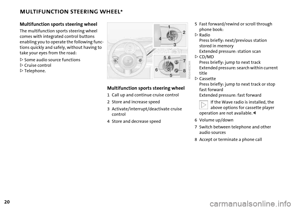
The multifunction sports steering wheel
comes with integrated control buttons
enabling you to operate the following func-
tions quickly and safely, without having to
take your eyes from the road:
>Some audio source functions
>Cruise control
>Telephone.
Multifunction sports steering wheel
1 Call up and continue cruise control
2 Store and increase speed
3 Activate/interrupt/deactivate cruise
control
4 Store and decrease speed
5 Fast forward/rewind or scroll through
phone book:
>Radio
Press briefly: next/previous station
stored in memory
Extended pressure: station scan
>CD/MD
Press briefly: jump to next track
Extended pressure: search within current
title
>Cassette
Press briefly: jump to next track or stop
fast forward
Extended pressure: fast forward
If the Wave radio is installed, the
above options for cassette player
operation are not available.<
6 Volume up/down
7 Switch between telephone and other
audio sources
8 Accept or terminate a phone call
Page 44 of 168

42
SAFE SEATING POSITION
The ideal seating position can make a vital
contribution to relaxed, relatively fatigue-
free driving. Together with the safety belts
and airbags, the seating position also plays
an important role in providing occupants
with maximum levels of passive safety in
an accident. To ensure that the safety sys-
tems operate with optimal efficiency, we
strongly urge you to observe the instruc-
tions contained in the following section.
For additional information about trans-
porting children safely, refer to page50.
Airbags
Always maintain an adequate dis-
tance between yourself and all of the
airbags. Always hold the steering wheel by
the rim with the hands at the 9 and
3 o'clock positions to keep any chance of
injury to hands or arms to an absolute min-
imum, should the airbag be deployed.
No one and nothing is to come between
the airbags and the seat occupant. Do not
use the front passenger airbag cover as a
storage surface for objects of any kind.
Ensure that the front passenger is correctly
seated, e.g. that no feet or legs are propped
against the dashboard. Otherwise, leg
injury could result if the front passenger
airbag suddenly deployed.
Make sure that passengers do not lean
their heads against the side or head airbag,
as injuries could result if the side airbags
were triggered.<
Even if all these instructions are followed, it
cannot entirely be ruled out that in some
circumstances injury may result from con-
tact with the airbags. In sensitive individu-
als, the ignition and inflation noise may
induce a mild hearing loss that is usually
temporary.
For airbag locations and additional infor-
mation on airbags, refer to page75.
Head restraint
A correctly adjusted head restraint reduces
the risk of injury to the cervical spine in the
event of an accident.
Adjust the head restraint in such a
way that it is centered roughly at ear
level. Otherwise, there is an increased risk
of injury in the event of an accident.<
Safety belt
Fasten your safety belt before each drive.
Airbags are an additional safety device and
work in conjunction with the safety belts,
but do not replace them. Your vehicle is
equipped with four seats, each of which is
provided with a safety belt.
Expectant mothers should always
wear their safety belts, taking care to
position the belt in the pelvic area against
the lower hips, where it will not exert pres-
sure against the abdomen.
Never allow more than one person to wear
a single safety belt. Never allow infants or
small children to ride in a passenger's lap.
Do not route the belt across your neck, or
run it across sharp edges. Be sure that the
belt does not become caught or jammed.
Avoid twisting the belt while routing it
firmly across the hips and shoulder; wear it
as snugly against your body as possible and
do not allow it to rest against hard or frag-
ile objects. Otherwise, the belt in the pelvic
area could slide over the hips in the event
of a frontal impact, leading to abdominal
injury. Avoid wearing bulky clothing and
pull the belt in the upper-body area upward
periodically to retension it. Otherwise, the
restraining effect of the safety belt could
be diminished.<
For information on using the safety belts,
refer to page46.
Page 46 of 168

44
SEAT ADJUSTMENT HEAD RESTRAINTS
Lumbar support*
You can adjust the contour of the backrest
for additional support in the curvature of
your spine's lumbar region. The upper hips
and spinal column receive supplementary
support to help you maintain a relaxed,
upright posture.
Turn the wheel.
The curvature is increased or decreased.
Backrest tilt
1. Pull up the lever at the inside of the seat
2. Apply weight to or remove weight from
the backrest as required
3. Release the lever so that the backrest
locks into place.
Adjusting
To raise: pull the head restraint upward.
To lower: press the button, see arrow 1,
and push the head restraint downward.
A correctly adjusted head restraint reduces
the risk of injury to the cervical spine in the
event of an accident.
Page 49 of 168

47
OVERVIEW REPAIRS OPERATIONCONTROLS DATA INDEX
SAFETY BELTS SEAT HEATING* STEERING WHEEL
Damaged safety belts
If the safety belts are damaged or
stretched in an accident: have the
safety belts including the seat-belt tension-
ers and the belt anchors checked. Have the
necessary work carried out only by a MINI
Dealer or a workshop that has specially
trained personnel working in accordance
with the specifications of the MINI manu-
facturer, otherwise correct operation of
these safety systems is not ensured.<
Press once for each temperature level.
The highest preselected temperature is set
when two LEDs are lit.
To switch off:
Press the button for a longer period.Do not adjust the steering wheel
while the vehicle is moving; other-
wise unexpected movement could increase
the accident risk.<
Settings
1. Push the locking lever downward
2. Adjust the desired steering wheel posi-
tion
3. Pull the lever back in.
Page 55 of 168
53
OVERVIEW REPAIRS OPERATIONCONTROLS DATA INDEX
IGNITION LOCK STARTING THE ENGINE
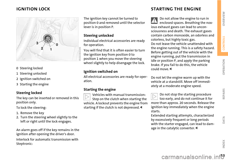
0 Steering locked
1 Steering unlocked
2 Ignition switched on
3 Starting the engine
Steering locked
The key can be inserted or removed in this
position only.
To lock the steering:
1. Remove the key
2. Turn the steering wheel slightly to the
left or right until the lock engages.
An alarm goes off if the key remains in the
ignition after opening the driver's door.
Interlock for automatic transmission with
Steptronic:
The ignition key cannot be turned to
position 0 and removed until the selector
lever is in position P.
Steering unlocked
Individual electrical accessories are ready
for operation.
You will find that it is often easier to turn
the ignition key from position 0 to
position 1 when you move the steering
wheel slightly to help disengage the lock.
Ignition switched on
All electrical accessories are ready for oper-
ation.
Starting the engine
Vehicles with manual transmission:
Step on the clutch when starting the
vehicle. A lockout prevents the engine from
starting if the clutch is not depressed.<
Do not allow the engine to run in
enclosed spaces. Breathing the nox-
ious exhaust gases can lead to uncon-
sciousness and death. The exhaust gases
contain carbon monoxide, an odorless and
colorless, but highly toxic gas.
Do not leave the vehicle unattended with
the engine running. This is a safety hazard.
Before getting out of the vehicle with the
engine running, put the transmission in
idle or position P, and apply the parking
brake. If you fail to do this, the vehicle
could move.<
Do not let the engine warm up with the
vehicle at a standstill. Move off immedi-
ately at a moderate engine speed.
Do not stop the starting procedure
too early, and do not continue it for
more than approx. 20 seconds. Release the
ignition key immediately when the engine
starts.
Extended starting attempts, characterized
by excessively frequent or long periods
with the starter engaged, can lead to dam-
age in the catalytic converter.<