ECU MINI Hardtop 2 Door 2015 Owner's Manual
[x] Cancel search | Manufacturer: MINI, Model Year: 2015, Model line: Hardtop 2 Door, Model: MINI Hardtop 2 Door 2015Pages: 251, PDF Size: 11.4 MB
Page 30 of 251

This device complies with part 15 of the FCC
Rules. Operation is subject to the following two
conditions:▷This device may not cause harmful interfer‐
ence, and▷this device must accept any interference re‐
ceived, including interference that may
cause undesired operation.
Any unauthorized modifications or changes to
these devices could void the user's authority to
operate this equipment.
Without remote control From the outside Locking from the outside
Do not lock the vehicle from the outside
with people inside the car, as the vehicle can‐
not be unlocked from inside without special
knowledge. ◀
Remove the key before pulling the door
handle
Before pulling the outside door handle, remove
the key to avoid damaging the paintwork and
the key. ◀
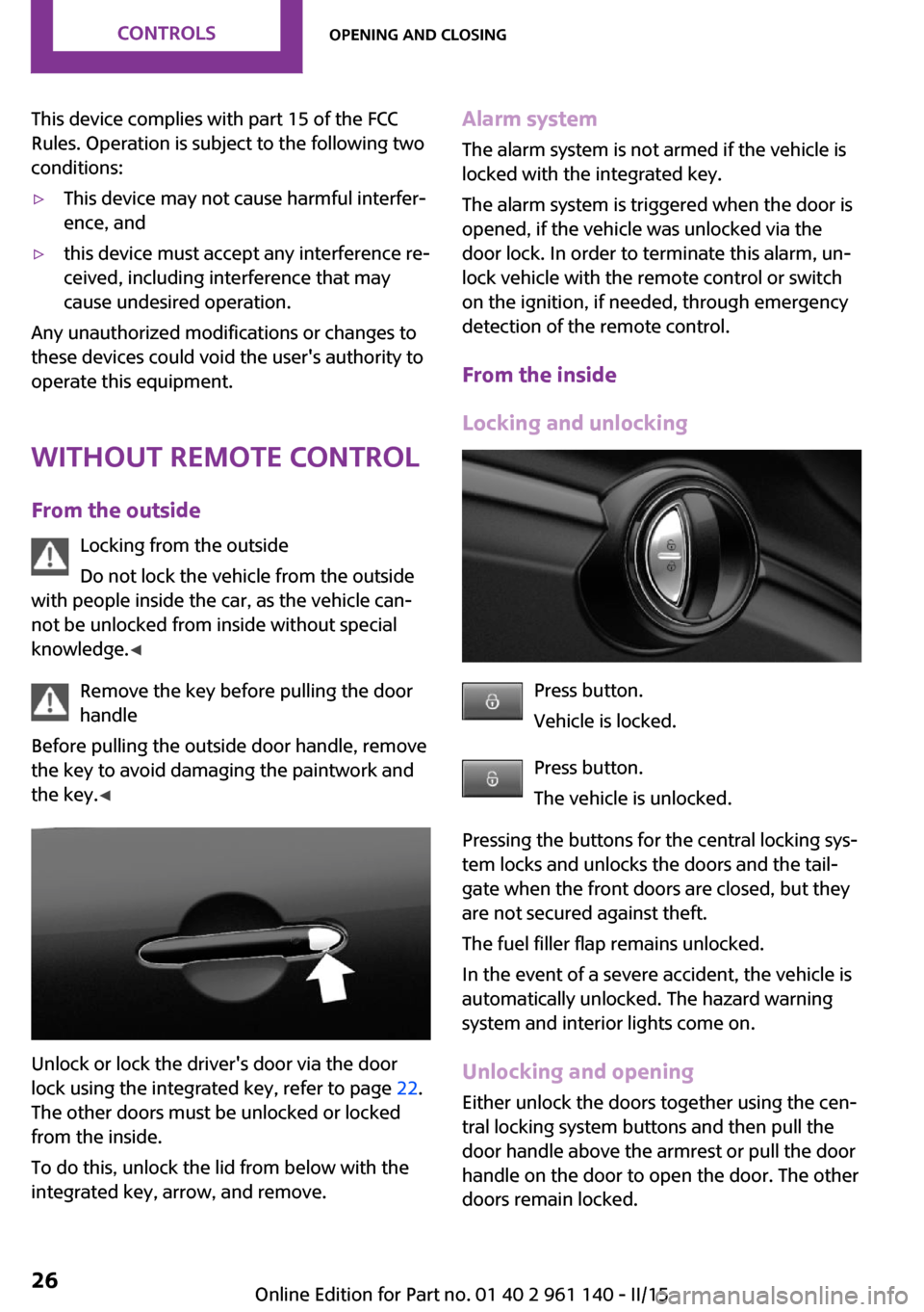
Unlock or lock the driver's door via the door
lock using the integrated key, refer to page 22.
The other doors must be unlocked or locked
from the inside.
To do this, unlock the lid from below with the
integrated key, arrow, and remove.
Alarm system
The alarm system is not armed if the vehicle is
locked with the integrated key.
The alarm system is triggered when the door is
opened, if the vehicle was unlocked via the
door lock. In order to terminate this alarm, un‐
lock vehicle with the remote control or switch
on the ignition, if needed, through emergency
detection of the remote control.
From the inside
Locking and unlocking
Press button.
Vehicle is locked.
Press button.
The vehicle is unlocked.
Pressing the buttons for the central locking sys‐
tem locks and unlocks the doors and the tail‐
gate when the front doors are closed, but they
are not secured against theft.
The fuel filler flap remains unlocked.
In the event of a severe accident, the vehicle is
automatically unlocked. The hazard warning
system and interior lights come on.
Unlocking and opening
Either unlock the doors together using the cen‐
tral locking system buttons and then pull the
door handle above the armrest or pull the door
handle on the door to open the door. The other
doors remain locked.
Seite 26CONTROLSOpening and closing26
Online Edition for Part no. 01 40 2 961 140 - II/15
Page 47 of 251

Transporting children safelyVehicle features and op‐
tions
This chapter describes all standard, country-
specific and optional features offered with the
series. It also describes features that are notnecessarily available in your car, e. g., due to
the selected options or country versions. This
also applies to safety-related functions and sys‐
tems. The respectively applicable country provi‐
sions must be observed when using the respec‐
tive features and systems.
The right place for children
Note
Children in the vehicle
Do not leave children unattended in the
vehicle; otherwise, they could endanger them‐
selves and other persons, e.g., by opening the
doors. ◀
Children should always be in the rear Accident research shows that the safest place
for children is in the back seat.
Transporting children in the rear
Only transport children younger than
13 years of age or shorter than 5 ft/150 cm in
the rear in child restraint systems provided in
accordance with the age, weight and size of
the child; otherwise, there is an increased risk
of injury in an accident.
Children 13 years of age or older must wear a
safety belt as soon as a suitable child restraint system can no longer be used due to their age,
weight and size. ◀
Children on the front passenger seat
Should it ever be necessary to use a child re‐
straint system in the front passenger seat,
make sure that the front, knee and side airbags
on the front passenger side are deactivated.
Automatic deactivation of front-seat passenger
airbags, refer to page 80.Note
Deactivating the front-seat passenger air‐
bags
If a child restraint system is used in the front
passenger seat, deactivate the front-seat pas‐
senger airbags; otherwise, there is an increased
risk of injury to the child when the airbags are
activated, even with a child restraint system. ◀
Installing child re‐
straint systems
Hints Manufacturer's information for child re‐straint systems
To select, mount and use child restraint sys‐
tems, observe the information provided by the
system manufacturer; otherwise, the protective
effect can be lost. ◀
Ensuring the stability of the child seat
When installing child restraint systems,
make sure that the child seat is securely fas‐
tened to the backrest of the seat. Angle and
headrest of the backrest might need to be ad‐
justed or possibly be removed. Make sure that
all backrests are securely locked. Otherwise the
stability of the child seat can be affected, andSeite 43Transporting children safelyCONTROLS43
Online Edition for Part no. 01 40 2 961 140 - II/15
Page 48 of 251

there is an increased risk of injury because of
unexpected movement of the seat backrest. ◀
In order to faciliate the installation of a back-
facing child restraint system in the rear:
move the front passenger's seat as far up as
possible before folding down the backrest.
On the front passenger seat
Deactivating airbags
After installing a child restraint system in the
front passenger seat, make sure that the front,
knee and side airbags on the front passenger
side are deactivated.
Deactivate the front-seat passenger airbags au‐
tomatically, refer to page 80.
Deactivating the front-seat passenger air‐
bags
If a child restraint system is used in the front
passenger seat, deactivate the front-seat pas‐
senger airbags; otherwise, there is an increased
risk of injury to the child when the airbags are
activated, even with a child restraint system. ◀
Seat position and height
Before installing a child restraint system, move
the front passenger seat as far back as possible
and adjust its height to the highest and thus
best possible position for the belt and to offer
optimal protection in the event of an accident.
If the upper anchorage of the safety belt is lo‐
cated in front of the belt guide of the child seat,move the passenger seat carefully forward until
the best possible belt guide position is reached.
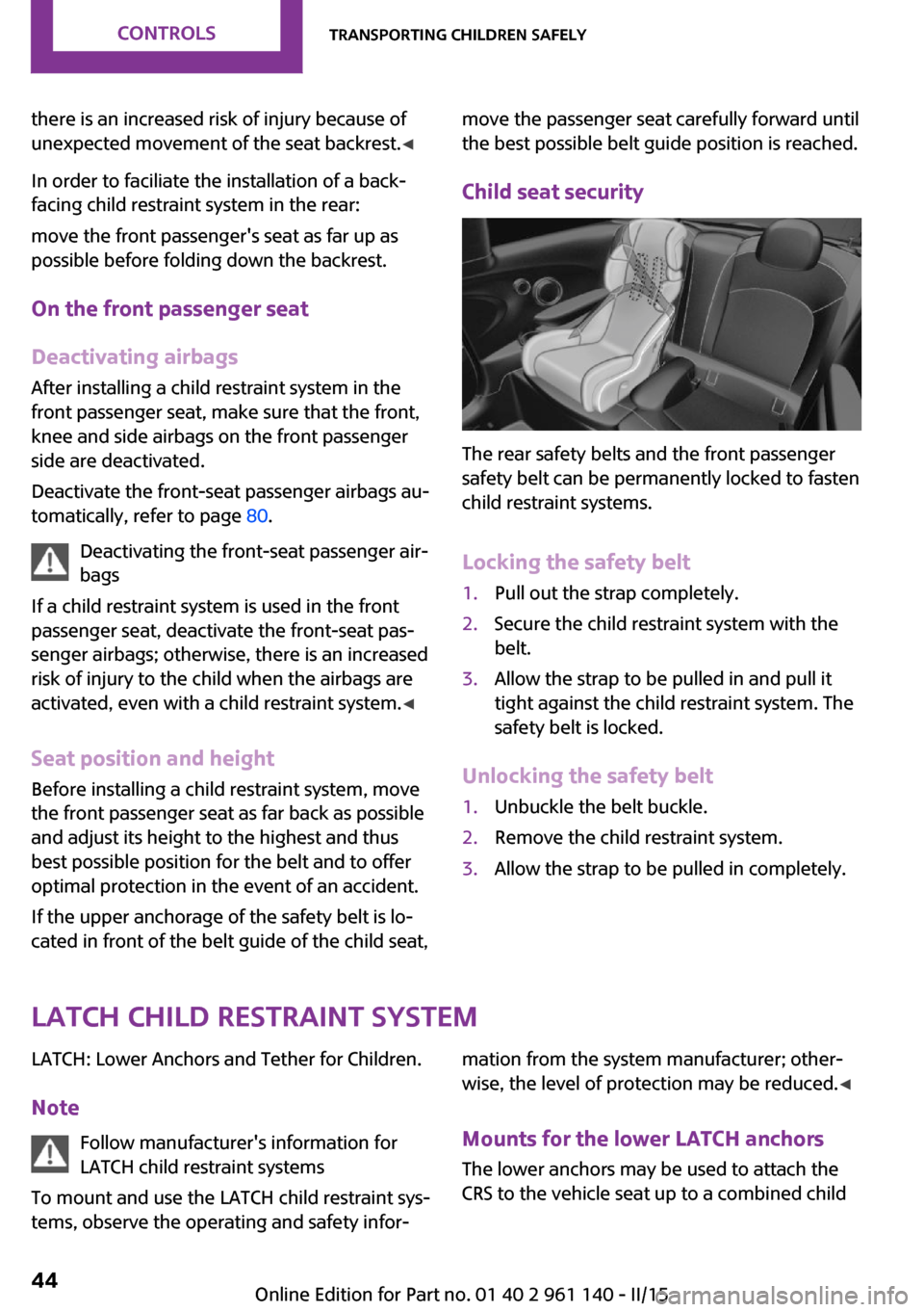
Child seat security
The rear safety belts and the front passenger
safety belt can be permanently locked to fasten
child restraint systems.
Locking the safety belt
1.Pull out the strap completely.2.Secure the child restraint system with the
belt.3.Allow the strap to be pulled in and pull it
tight against the child restraint system. The
safety belt is locked.
Unlocking the safety belt
1.Unbuckle the belt buckle.2.Remove the child restraint system.3.Allow the strap to be pulled in completely.
LATCH child restraint system
LATCH: Lower Anchors and Tether for Children.
Note Follow manufacturer's information for
LATCH child restraint systems
To mount and use the LATCH child restraint sys‐
tems, observe the operating and safety infor‐mation from the system manufacturer; other‐
wise, the level of protection may be reduced. ◀
Mounts for the lower LATCH anchors
The lower anchors may be used to attach the
CRS to the vehicle seat up to a combined childSeite 44CONTROLSTransporting children safely44
Online Edition for Part no. 01 40 2 961 140 - II/15
Page 49 of 251

and CRS weight of 65 lb when the child is re‐
strained by the internal harnesses.
Properly engage the lower LATCH an‐chors
Make sure that the lower LATCH anchors have
properly engaged and that the child restraint
system is resting snugly against the backrest;
otherwise, the degree of protection may be re‐
duced. ◀
Before mounting the LATCH child restraint sys‐
tem, pull the belt away from the child restraint
system.
Position The corresponding symbol shows the
mounts for the lower LATCH anchors.
Seats equipped with lower anchors are
marked with a pair, 2, of LATCH sym‐
bols. It is not recommended to use the
inner lower anchors of standard outer LATCH
positions to fasten a child restraint system on
the middle seat. Use the vehicle seat belt in‐
stead for the middle seat.
Assembly of LATCH child restraint
systems1.Mount the child restraint system; refer to
the user's manual of the system.2.Ensure that both LATCH anchors are prop‐
erly connected.
Child restraint fixing system with a
tether strap
Note Mounting eyelets
Use the mounting eyes only for the upper
retaining strap to secure child restraint systems;
otherwise, the mounting eyes could be dam‐
aged. ◀
Mounting points
The respective symbol shows the an‐chor for the upper retaining strap. Seats
with an upper Top Tether are marked
with this symbol. It can be found on the rear
seat backrest or the rear window shelf.
Retaining strap guide Retaining strap
Make sure that the upper retaining strap
is not passed over the head restraints or sharp
edges and is not twisted up to the upper
mounting points; otherwise, the belt cannot
properly secure the child restraint system in an
accident. ◀1Direction of travel2Head restraint3Hook for upper retaining strap4Mounting point/eye5Seat backrest6Upper retaining strap
Attaching the upper retaining strap to
the mounting point
1.Raise the head restraint if needed.2.Guide the upper retaining strap between
the supports of the head restraint.3.Attach the hook of the retaining strap to
the mounting eye on the rear seat.4.Tighten the retaining strap by pulling it
down.Seite 45Transporting children safelyCONTROLS45
Online Edition for Part no. 01 40 2 961 140 - II/15
Page 50 of 251

No persons on the back seat when there
is a child restraint system with an upper
retaining strap on the front passenger seat.
When there is a child restraint system with an
upper retaining strap on the front passenger
seat, no one should sit in the back seat directly
behind it, otherwise there is an increased risk of
injury due to the upper retaining strap. ◀
Upper retaining strap when the backrest
is folded down
When the backrest is folded down, do not
guide the belt through the head restraint sup‐
ports on the backrest; otherwise the belt may
not secure the child restraint system properly in
case of an accident ◀
ON 5-door models: Lock‐
ing the doors and win‐
dows
Rear doors
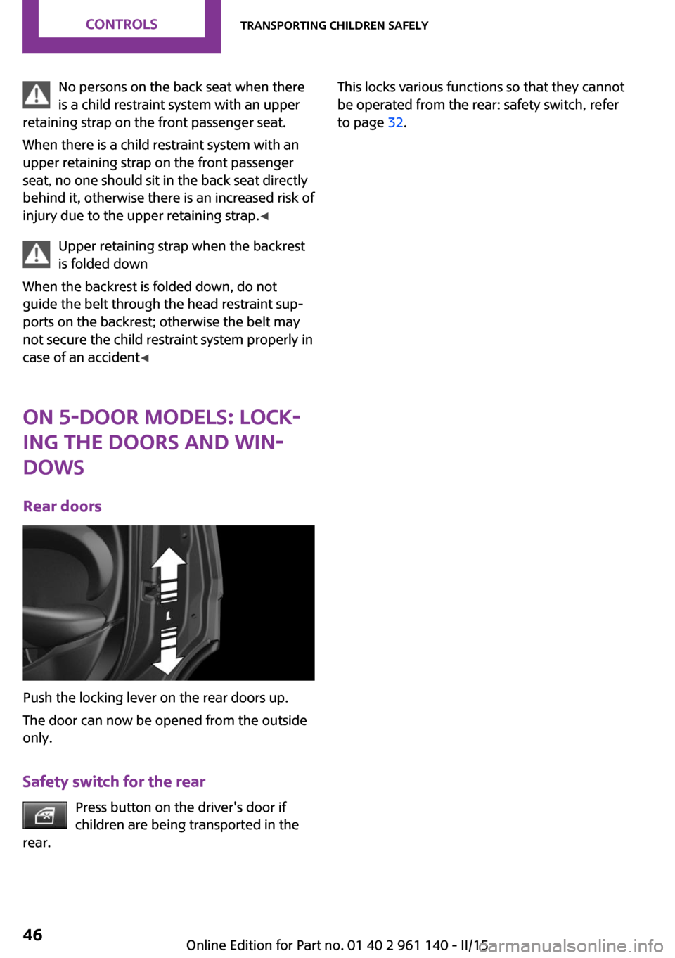
Push the locking lever on the rear doors up.
The door can now be opened from the outside
only.
Safety switch for the rear Press button on the driver's door if
children are being transported in the
rear.
This locks various functions so that they cannot
be operated from the rear: safety switch, refer
to page 32.Seite 46CONTROLSTransporting children safely46
Online Edition for Part no. 01 40 2 961 140 - II/15
Page 52 of 251

▷After approx. 8 minutes.▷When the vehicle is locked using the central
locking system.▷Shortly before the battery is discharged
completely, so that the engine can still be
started.
The radio-ready state remains active if, e.g., the
ignition is automatically switched off for the fol‐
lowing reasons:
▷Opening or closing the driver's door.▷Unfastening of the driver's safety belt.▷When automatically switching from low
beams to parking lights.
If the engine is switched off and the ignition is
switched on, the system automatically switches
to the radio-ready state if the lights are turned
off or, if correspondingly equipped, the day‐
time running lights are activated.
Starting the engine
Hints Enclosed areas
Do not let the engine run in enclosed
areas, since breathing in exhaust fumes may
lead to loss of consciousness and death. The
exhaust gases contain carbon monoxide, an
odorless and colorless but highly toxic gas. ◀
Unattended vehicle
Do not leave the vehicle unattended with
the engine running; doing so poses a risk of
danger.
Before leaving the vehicle with the engine run‐
ning, set the parking brake and place the trans‐
mission in selector lever position P or N to pre‐
vent the vehicle from moving. ◀
Repeated starting in quick succession
Avoid trying to start the vehicle repeat‐
edly and in quick succession. Otherwise, the
fuel is not burned or is inadequately burned,
posing a risk of overheating and damage to the
catalytic converter. ◀
Do not wait for the engine to warm-up while
the vehicle remains stationary. Start driving at
moderate engine speeds.
Steptronic transmission
Starting the engine1.Depress the brake pedal.2.Engage selector lever position P or N.3.Press the Start/Stop button.
The ignition is activated automatically for a cer‐
tain time and is stopped as soon as the engine
starts.
Manual transmission
Starting the engine
1.Depress the brake pedal.2.Press on the clutch pedal and shift to neu‐
tral.3.Press the Start/Stop button.
The ignition is activated automatically for a cer‐
tain time and is stopped as soon as the engine
starts.
Engine stop
Hints Take the remote control with you
Take the remote control with you when
leaving the vehicle so that children, e.g., cannot
start the engine. ◀
Apply parking brake and further secure
the vehicle if needed.
Set the parking brake firmly when parking; oth‐
erwise, the vehicle could roll. On steep upward
and downward inclines, further secure the ve‐
Seite 48CONTROLSDriving48
Online Edition for Part no. 01 40 2 961 140 - II/15
Page 67 of 251

High-beam AssistantHigh-beam Assistant is switched on.
High beams are activated and off auto‐
matically as a function of the traffic sit‐
uation.
For additional information, refer to High-beam
Assistant, refer to page 75.
Cruise control The system is switched on. It maintains
the speed that was set using the control
elements on the steering wheel.
Blue lights
High beams High beams are activated.
For additional information, refer to High
beams, refer to page 52.
General lamps At least one Check Control message is
displayed or is stored. The symbol is
shown in the display of the instrument
cluster.
Text messages
Text messages in combination with a symbol in
the instrument cluster explain a Check Control
message and the meaning of the indicator and
warning lights.
Supplementary text messages Additional information, such as on the cause of
an error or the required action, can be called up
via Check Control.
With urgent messages the added text will be
automatically displayed on the radio display.
To view the entire text line for line: turn the
right-hand knob on the radio.Hiding Check Control messages
Press the onboard computer button on the turn
signal lever.
▷Some Check Control messages are dis‐
played continuously and are not cleared
until the malfunction is eliminated. If sev‐
eral malfunctions occur at once, the mes‐
sages are displayed consecutively.
These messages can be faded for approx.
8 seconds. After this time, they are dis‐
played again automatically.▷Other Check Control messages are faded
automatically after approx. 20 seconds.
They are stored and can be displayed again
later.
Displaying stored Check Control
messages
1. Press button.2. "Vehicle Info"3."Vehicle status"4."Check Control"5.Selecting the desired Check Control mes‐
sage
Messages after trip completion
Special messages displayed while driving are
displayed again after the ignition is switched
off.
Seite 63DisplaysCONTROLS63
Online Edition for Part no. 01 40 2 961 140 - II/15
Page 93 of 251

▷LED lights up orange or goes out respective
to their individual settings.
Adjust as needed. Individual settings are stored
for the profile currently in use.
Press button again:
▷All Intelligent Safety systems are
activated.▷The LED lights up green.
Hold down button:
▷All Intelligent Safety systems are
turned off.▷The LED goes out.
Setting the warning time
The warning time can be set on the radio.
1.Intelligent Safety button
The intelligent safety menu is displayed for
a brief time on the radio display.2."Front. Coll. Warn."3."Warning time"4.Setting the desired warning time
The selected warning time is stored for the pro‐
file currently in use.
Warning with braking function
Display
If a collision with a vehicle detected in this way
is imminent, a warning symbol appears on the
instrument cluster.
SymbolMeasureThe vehicle lights up red: prewarning.
Brake and increase distance.The vehicle flashes red and an acous‐
tic signal sounds: acute warning.
You are requested to intervene by
braking or make an evasive maneu‐
ver.Prewarning
This warning is issued, e.g., when there is the
impending danger of a collision or the distance
to the vehicle ahead is too small.
The driver must intervene actively when there
is a prewarning.
Acute warning with braking function
Warning of the imminent danger of a collision
when the vehicle approaches another object at
a relatively high differential speed.
The driver must intervene actively when there
is an acute warning. If necessary, the driver is
assisted by a minor automatic braking inter‐
vention in a possible risk of collision.
Acute warnings can also be triggered without
previous prewarning.
Braking intervention
The warning prompts the driver himself/herself
to react. During a warning, the maximum brak‐
ing force is used. Premise for the brake booster
is sufficiently quick and sufficiently hard step‐
ping on the brake pedal. The system can assist
with some braking intervention if there is risk of
a collision. At low speeds vehicles may thus come to a complete stop.
Manual transmission: During a braking inter‐
vention up to a complete stop, the engine may
be shut down.
The braking intervention is executed only if DSC Dynamic Stability Control is switched on.
The braking intervention can be interrupted by
stepping on the accelerator pedal or by actively
moving the steering wheel.
Object detection can be restricted. Limitations
of the detection range and functional restric‐
tions are to be considered.
System limits
Detection range The system's detection potential is limited.Seite 89SafetyCONTROLS89
Online Edition for Part no. 01 40 2 961 140 - II/15
Page 96 of 251

Warning with braking function
Display
If a collision with a person detected in this way
is imminent, a warning symbol appears on the
instrument cluster.
The red symbol is displayed and a signal
sounds.
Intervene immediately by braking or
make an evasive maneuver.
Braking intervention
The warning prompts the driver himself/herself
to react. During a warning, the maximum brak‐
ing force is used. Premise for the brake booster
is sufficiently quick and sufficiently hard step‐
ping on the brake pedal. The system can assist
with some braking intervention if there is risk of
a collision. At low speeds vehicles may thus come to a complete stop.
Manual transmission: During a braking inter‐
vention up to a complete stop, the engine may
be shut down.
The braking intervention is executed only if DSC
Dynamic Stability Control is switched on.
The braking intervention can be interrupted by
stepping on the accelerator pedal or by actively
moving the steering wheel.
Object detection can be restricted. Limitations
of the detection range and functional restric‐
tions are to be considered.
System limits
Detection range The detection potential of the camera is lim‐
ited.
Thus a warning might not be issued or be is‐
sued late.
E. g. the following situations may not be de‐
tected:▷Partially covered pedestrians.▷Pedestrians that are not detected as such
because of the viewing angle or contour.▷Pedestrians outside of the detection range.▷Pedestrians having a body size less than
32 in/80 cm.
Functional limitations
The system may not be fully functional or may
not be available in the following situations:
▷In heavy fog, rain, sprayed water or snow‐
fall.▷In tight curves.▷If the camera viewing field or the front
windshield are dirty or covered.▷If the driving stability control systems are
deactivated, e.g. DSC OFF.▷Up to 10 seconds after the start of the en‐
gine, via the Start/Stop knob.▷During calibration of the camera immedi‐
ately after vehicle shipment.▷If there is constant blinding effects because
of oncoming light, e. g., from the sun low in
the sky.▷When it is dark outside.
Brake force display
The concept
▷During normal brake application, the brake
lights light up.Seite 92CONTROLSSafety92
Online Edition for Part no. 01 40 2 961 140 - II/15
Page 123 of 251

Interior equipmentVehicle features and op‐
tions
This chapter describes all standard, country-
specific and optional features offered with the
series. It also describes features that are not
necessarily available in your car, e. g., due to
the selected options or country versions. This
also applies to safety-related functions and sys‐
tems. The respectively applicable country provi‐
sions must be observed when using the respec‐
tive features and systems.
Universal Integrated Re‐
mote Control
The concept
The Universal Integrated Remote Control can
operate up to 3 functions of remote-controlled
systems such as garage door drives or lighting
systems. The Universal Integrated Remote Con‐
trol replaces up to 3 different hand-held trans‐
mitters. To operate the remote control, the but‐
tons on the interior rearview mirror must be
programmed with the desired functions. The
hand-held transmitter for the particular system
is required in order to program the remote con‐
trol.
During programming
During programming and before activat‐
ing a device using the universal garage door
opener, ensure that there are no people, ani‐
mals or objects in the area of the remote-con‐
trolled device; otherwise, there is a risk of injury
or damage.
Also follow the safety instructions of the hand-
held transmitter. ◀
Before selling the vehicle, delete the stored
functions for the sake of security.Compatibility
If this symbol is printed on the packag‐
ing or in the instructions of the system
to be controlled, the system is generally
compatible with the Universal Integrated Re‐
mote Control.
If you have any questions, please contact:▷Your service center.▷www.homelink.com on the Internet.
HomeLink is a registered trademark of Gentex
Corporation.
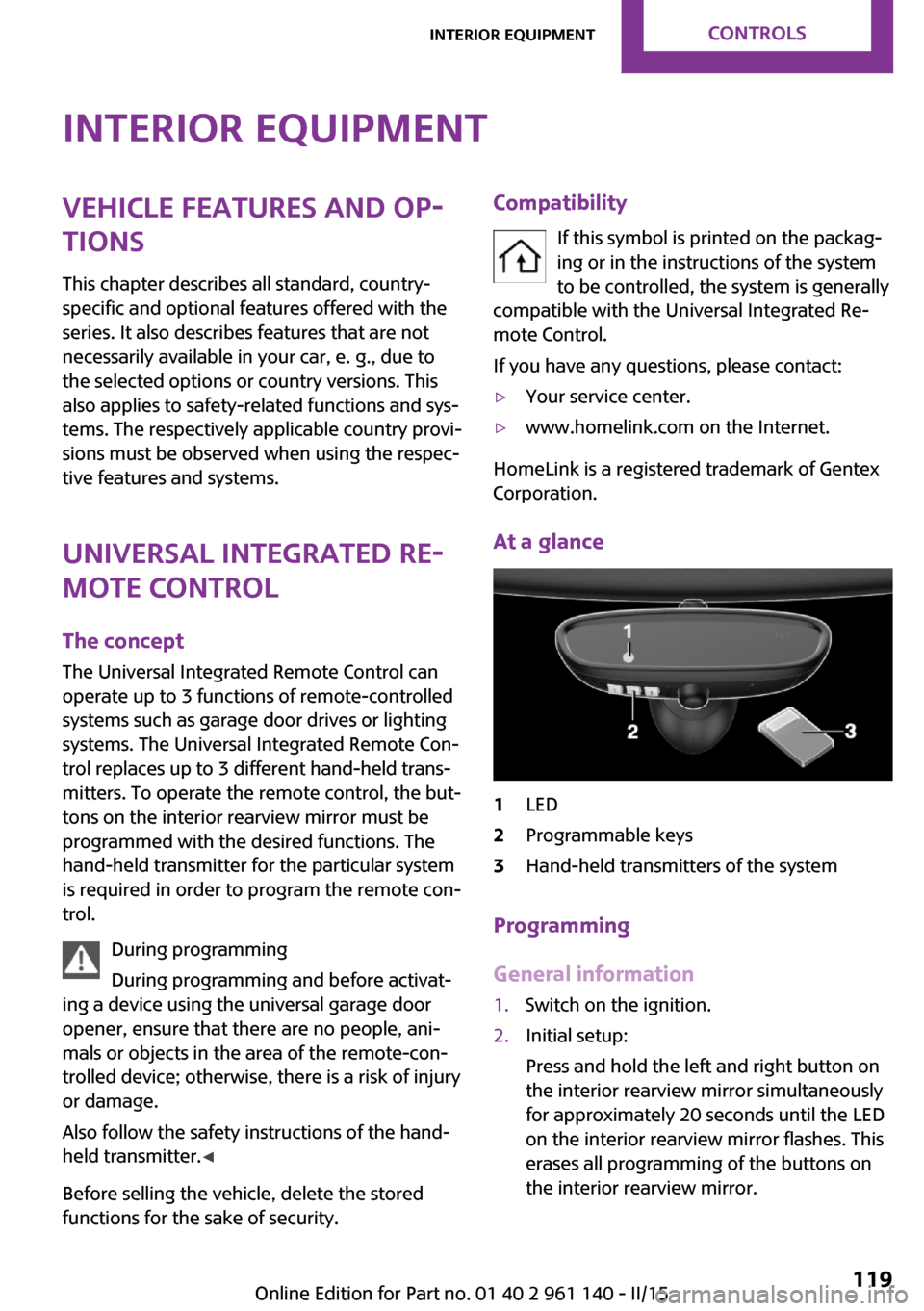
At a glance
1LED2Programmable keys3Hand-held transmitters of the system
Programming
General information
1.Switch on the ignition.2.Initial setup:
Press and hold the left and right button on
the interior rearview mirror simultaneously
for approximately 20 seconds until the LED
on the interior rearview mirror flashes. This
erases all programming of the buttons on
the interior rearview mirror.Seite 119Interior equipmentCONTROLS119
Online Edition for Part no. 01 40 2 961 140 - II/15