ECU MINI Hardtop 2 Door 2015 User Guide
[x] Cancel search | Manufacturer: MINI, Model Year: 2015, Model line: Hardtop 2 Door, Model: MINI Hardtop 2 Door 2015Pages: 251, PDF Size: 11.4 MB
Page 129 of 251

2.Pull the cargo cover out of the brackets on
the left and right.
Installation
1.Slide the cover forward horizontally into the
two side brackets until it audibly latches.2.Attach the left and right retaining straps at
the tailgate.
Enlarging the trunk
General information
The trunk can be enlarged by folding down the
rear seat backrest.
The rear seat backrest is divided into two parts
at a ratio of 60 to 40. The backrest of the left
seat is connected to the backrest center sec‐
tion.
Hints Danger of jamming
Before folding down the rear seat back‐
rests, ensure that the area of movement of the
backrests is clear. Ensure that no one is located
in or reaches into the area of movement of the
rear seat backrests. Otherwise, injury or dam‐
age may result. ◀
Ensuring the stability of the child seat
When installing child restraint systems,
make sure that the child seat is securely fas‐
tened to the backrest of the seat. Angle and
headrest of the backrest might need to be ad‐
justed or possibly be removed. Make sure that
all backrests are securely locked. Otherwise the
stability of the child seat can be affected, and
there is an increased risk of injury because of
unexpected movement of the seat backrest. ◀
Using the middle safety belt
If the middle safety belt in the rear is
used, the larger side of the backrest must be
locked. Otherwise, the safety belt will not have
a restraining effect. ◀
Push the headrests down, before the
backrests are folded down
Before folding down the rear seat backrests,
make sure that the corresponding headrest is
pushed all the way down; otherwise, damage
may result. ◀
Folding down rear seat backrest The rear seat backrests can be folded down
from the front or from the trunk.
Before the backrest is folded down, hook the
corresponding safety belt into the safety belt
on the side.
Pull the release upward and fold the backrest
toward the front.
Folding back the backrest Ensure that the lock is securely engaged
When you fold back the backrest make
sure that it locks in place. When this happens
the red warning field on the seat disappears.
Otherwise transported cargo could shoot into
the car's interior during braking or evasive ma‐
neuvers and endanger occupants. ◀
Seite 125Interior equipmentCONTROLS125
Online Edition for Part no. 01 40 2 961 140 - II/15
Page 131 of 251

Storage compartmentsVehicle features and op‐
tions
This chapter describes all standard, country-
specific and optional features offered with the
series. It also describes features that are not necessarily available in your car, e. g., due to
the selected options or country versions. This
also applies to safety-related functions and sys‐
tems. The respectively applicable country provi‐
sions must be observed when using the respec‐
tive features and systems.
Hints No loose objects in the car's interior
Do not stow any objects in the car's inte‐
rior without securing them; otherwise, they
may present a danger to occupants e.g., during
braking and evasive maneuvers. ◀
Do not place anti-slip mats on the dash‐
board
Do not place anti-slip mats on the dashboard.
The mat materials could damage the dash‐
board. ◀
Overview
The following storage compartments are avail‐
able in the vehicle interior:▷Storage compartment in front of the cu‐
pholders.▷Storage tray in the center console.▷Glove compartment on the front passenger
side.▷Storage compartment above the glove
compartment.▷Storage compartment in the center arm‐
rest.▷Compartments in the doors.▷Pockets on the backrests of the front seats.
Glove compartment
Note Close the glove compartment again im‐mediately
Close the glove compartment immediately after
use while driving; otherwise, injury may occur
during accidents. ◀
Opening
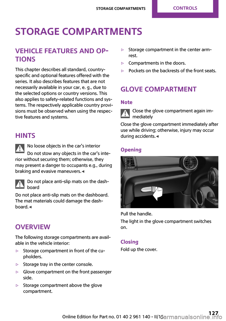
Pull the handle.
The light in the glove compartment switches
on.
Closing Fold up the cover.
Seite 127Storage compartmentsCONTROLS127
Online Edition for Part no. 01 40 2 961 140 - II/15
Page 133 of 251

Front
In the center console.Rear
On 3-door models: in front of the rear seats and
in the and in the side armrests.
On 5-door models: in front of the rear seats.
Clothes hooks Do not obstruct view
When suspending clothing from the
hooks, ensure that it will not obstruct the driv‐
er's view. ◀
No heavy objects
Do not hang heavy objects from the
hooks; otherwise, they may present a danger
to passengers during braking and evasive ma‐
neuvers. ◀
The clothes hooks are located above the side
windows in the rear.
Storage space under
cargo floor panel
Located under the cargo floor panel on the
right side is a trough for the onboard vehicle
tool kit.
To remove the onboard vehicle tool kit, fold the
right side of the cargo floor panel upward.
Variable trunk floor
With the variable trunk floor, the trunk can be
configured corresponding to transport require‐
ments. To do this, remove the trunk floor, and
insert it in the desired position.
Follow instructions on securing cargo, refer to
page 137.
Seite 129Storage compartmentsCONTROLS129
Online Edition for Part no. 01 40 2 961 140 - II/15
Page 134 of 251

Removing the cargo floor panel
On 5-door models: To change the position of
the cargo floor panel, first fold up the rear part
of the cargo floor panel.
Grasp the cargo floor panel in the rear and fold
slightly upward. Next, pull it backward from the
supports.
The cargo floor panel can be removed from the
trunk above the tail lamps.
Lower position
▷Larger objects can be transported.▷Space for smaller objects remains between
the fixed and variable trunk floor.Folded up position
The variable cargo floor panel may not be
used as a partition net to separate the
trunk and the vehicle interior.▷Only use the variable cargo floor in the
folded-up position when the backrests are
folded up and locked.▷Always secure cargo against shifting, using
straps, belts and lashing eyes, e.g.
If you don't follow these precautions you can
endanger vehicle's occupants and damage the
cargo floor during braking. ◀
Fold up the cargo floor panel in the lower posi‐
tion and push it behind the locks on the left
and right, arrow. You've reached the maximum
cargo height.
Upper position
▷With the backrests folded down, a long, flat
loading surface is produced.▷On 3-door models:
Maximum load in this position:
330 lbs/150 kg.Seite 130CONTROLSStorage compartments130
Online Edition for Part no. 01 40 2 961 140 - II/15
Page 139 of 251

▷Close all windows and the glass sunroof.▷Greatly increase the air flow from the vents.▷Drive moderately.
Hot exhaust systemHot exhaust system
High temperatures are generated in the
exhaust system.
Do not remove the heat shields installed and
never apply undercoating to them. Make sure
that flammable materials, e. g. hay, leaves,
grass, etc. do not come in contact with the hot
exhaust system while driving, while in idle posi‐
tion mode, or when parked. Such contact could
lead to a fire, resulting in an increased risk of
serious personal injury as well as property dam‐
age.
Do not touch hot exhaust pipes; otherwise,
there is a danger of getting burned. ◀
Mobile communication devices in the
vehicle
Mobile communication devices in the ve‐hicle
It is not recommended to use mobile phones,
such as mobile phones, in the vehicle interior
without a direct connection to an external aer‐
ial. Otherwise, the vehicle's electronics and mo‐
bile communication devices can interfere with
each other. In addition, there is no assurance
that the radiation generated during transmis‐
sion will be conducted away from the vehicle
interior. ◀
Hydroplaning Hydroplaning
When driving on wet or slushy roads, re‐
duce your speed to prevent hydroplaning. ◀
On wet or slushy roads, a wedge of water can
form between the tires and road surface.
This phenomenon is referred to as hydroplan‐
ing. It is characterized by a partial or complete
loss of contact between the tires and the road
surface, ultimately undermining your ability to
steer and brake the vehicle.
Driving through water Observe water level and speed
Do not exceed the maximum water level
and maximum speed; otherwise, the vehicle's
engine, the electrical systems and the transmis‐
sion may be damaged. ◀
Drive through calm water only if it is not deeper
than 9.8 inches/25 cm and at this height, no
faster than walking speed, up to 3 mph/5 km/h.
Braking safely Your vehicle is equipped with ABS as a standard
feature.
Applying the brakes fully is the most effective
way of braking in situations needed.
Steering is still responsive. You can still avoid
any obstacles with a minimum of steering ef‐
fort.
Pulsation of the brake pedal and sounds from
the hydraulic circuits indicate that ABS is in its
active mode.
Objects in the area around the pedals No objects in the area around the pedals
Keep floor mats, carpets, and any other
objects out of the pedal area; otherwise, the
function of the pedals could be impeded while
driving and create the risk of an accident.
Do not place additional floor mats over existing
mats or other objects.
Only use floor mats that have been approved
for the vehicle and can be properly attached to
floor.
Ensure that the floor mats are securely fastened
again after they were removed for cleaning,
e.g. ◀Seite 135Things to remember when drivingDRIVING TIPS135
Online Edition for Part no. 01 40 2 961 140 - II/15
Page 141 of 251

LoadingVehicle features and op‐tions
This chapter describes all standard, country-
specific and optional features offered with the
series. It also describes features that are not
necessarily available in your car, e. g., due to
the selected options or country versions. This
also applies to safety-related functions and sys‐
tems. The respectively applicable country provi‐
sions must be observed when using the respec‐
tive features and systems.
Hints Overloading the vehicle
To avoid exceeding the approved ca‐
pacity of the tires, never overload the vehicle. Overloading can lead to overheating and in‐
creases the rate at which damage develops in‐
side the tires. This could result in a sudden loss
of tire inflation pressure. ◀
No fluids in the cargo area
Make sure that fluids do not leak into the
cargo area; otherwise, the vehicle may be dam‐ aged. ◀
Heavy and hard objects
Do not stow any heavy and hard objects
in the car's interior without securing them; oth‐
erwise, they may present a danger to occu‐
pants, e.g., during braking and evasive maneu‐
vers. ◀Determining the load
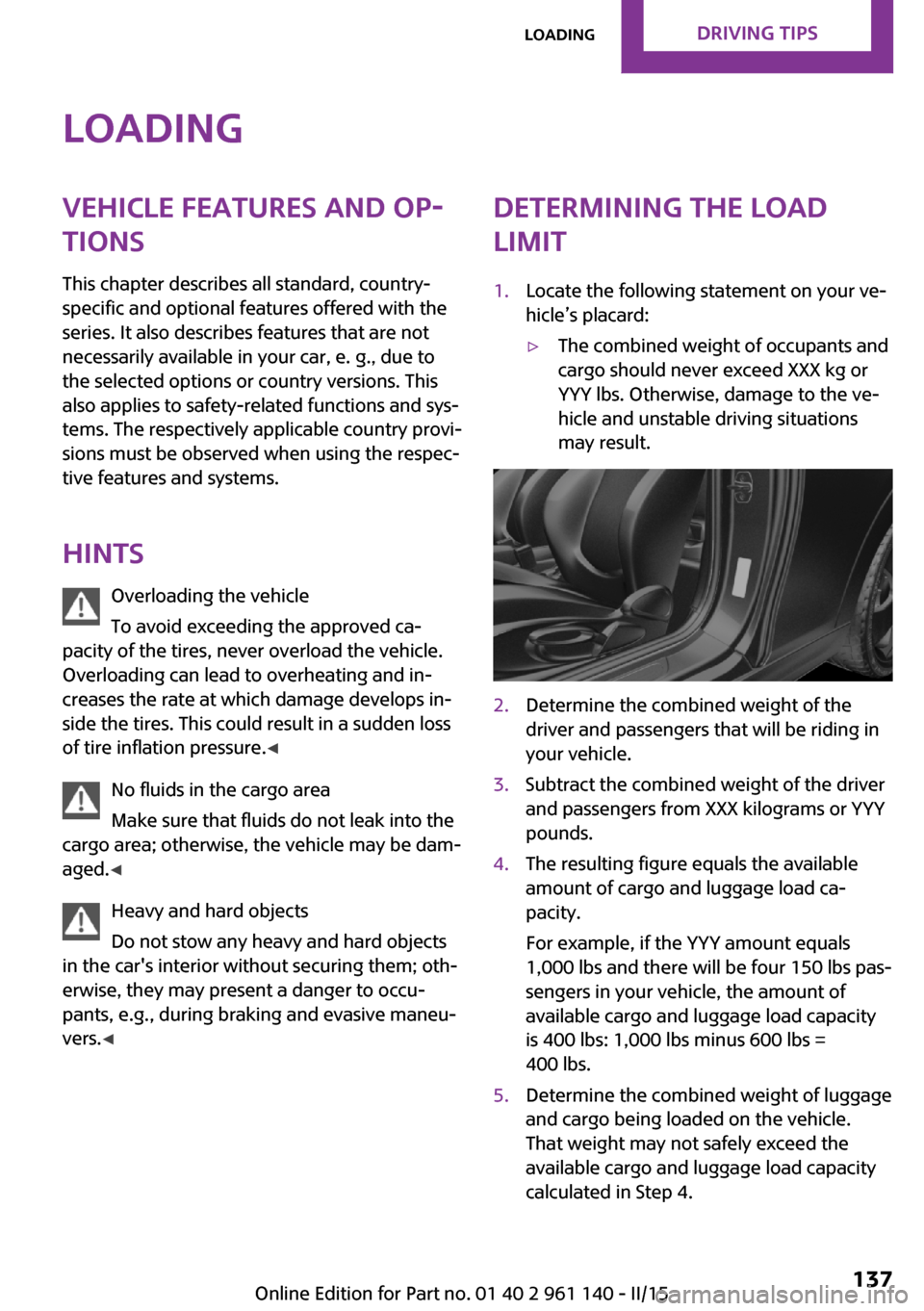
limit1.Locate the following statement on your ve‐
hicle’s placard:▷The combined weight of occupants and
cargo should never exceed XXX kg or
YYY lbs. Otherwise, damage to the ve‐
hicle and unstable driving situations
may result.2.Determine the combined weight of the
driver and passengers that will be riding in
your vehicle.3.Subtract the combined weight of the driver
and passengers from XXX kilograms or YYY
pounds.4.The resulting figure equals the available
amount of cargo and luggage load ca‐
pacity.
For example, if the YYY amount equals
1,000 lbs and there will be four 150 lbs pas‐
sengers in your vehicle, the amount of
available cargo and luggage load capacity
is 400 lbs: 1,000 lbs minus 600 lbs =
400 lbs.5.Determine the combined weight of luggage
and cargo being loaded on the vehicle.
That weight may not safely exceed the
available cargo and luggage load capacity
calculated in Step 4.Seite 137LoadingDRIVING TIPS137
Online Edition for Part no. 01 40 2 961 140 - II/15
Page 142 of 251

LoadOn 3-door modelsOn 5-door models
The maximum load is the sum of the weight of
the occupants and the cargo.
The greater the weight of the occupants, the
less cargo that can be transported.
Stowing cargo
▷Cover sharp edges and corners on the
cargo.▷Heavy cargo: stow as far forward as possi‐
ble, directly behind and at the bottom of
the rear passenger seat backrests.▷Very heavy cargo: when the rear seat is not
occupied, secure each of the outer safety
belts in the opposite buckle.▷If necessary, fold down the rear backrests
to stow cargo.▷Do not stack cargo above the top edge of
the backrests.Securing cargo
Lashing eyes in the cargo area
Without storage compartment package: to se‐
cure the cargo there are two lashing eyes, ar‐
row 1, in the cargo area.
With storage compartment package: to secure
the cargo there are six lashing eyes, arrows 1
and 2, in the cargo area.
Securing cargo Securing cargo
Stow and secure the cargo as described;
otherwise it may present a danger to the occu‐
pants, e.g., during braking and evasive maneu‐
vers. ◀
▷Smaller and lighter items: secure with re‐
taining straps or with draw straps.▷Larger and heavy objects: secure with
cargo straps.
Attach the cargo straps, retaining straps or
draw straps to the lashing eyes in the trunk.
Roof-mounted luggagerack
Note Installation only possible with roof rack.
Roof racks are available as special accessories.
Seite 138DRIVING TIPSLoading138
Online Edition for Part no. 01 40 2 961 140 - II/15
Page 143 of 251

Securing
Follow the installation instructions of the roof
rack.
Loading Be sure that adequate clearance is maintained
for tilting and opening the glass sunroof.
Because roof racks raise the vehicle's center of
gravity when loaded, they have a major effect
on vehicle handling and steering response.
Therefore, note the following when loading and
driving:▷Do not exceed the approved roof/axle
loads and the approved gross vehicle
weight.▷Distribute the roof load uniformly.▷The roof load should not extend past the
loading area.▷Always place the heaviest pieces on the
bottom.▷Secure the roof luggage firmly, e.g., tie with
ratchet straps.▷Do not let objects project into the opening
path of the tailgate.▷Drive cautiously and avoid sudden acceler‐
ation and braking maneuvers. Take corners
gently.
Rear luggage rack
General information Installation only possible with rear luggage rack
preparation.
Rear racks are available as special accessories.
Note Follow the installation instructions of the rear
luggage rack.
Drive cautiously and avoid sudden acceleration
and braking maneuvers. Take corners gently.
SecuringCOOPER/COOPER D/ONE/ONE DCOOPER S/COOPER SD
The anchorage points, arrow 1, and the socket,
arrow 2, are located below the covers in the
bumper.
Remove the covers before installing the rear
luggage rack.
Power consumption Function of tail lights
Before driving off, check that the tail
lights of the rear luggage rack are functioning
properly; otherwise, there is a risk of endanger‐
ing other traffic. ◀
The rear luggage rack lights must not consume
more than:
▷Turn signals: 42 watts per side.▷Rear lights: 50 watts per side.▷Brake lights: 84 watts in total.▷Rear fog lights: 42 watts in total.Seite 139LoadingDRIVING TIPS139
Online Edition for Part no. 01 40 2 961 140 - II/15
Page 166 of 251

Bluetooth hands-free systemVehicle features and op‐
tions
This chapter describes all standard, country-
specific and optional features offered with the
series. It also describes features that are not
necessarily available in your car, e. g., due to
the selected options or country versions. This
also applies to safety-related functions and sys‐
tems. The respectively applicable country provi‐
sions must be observed when using the respec‐
tive features and systems.
The concept Mobile phones can be connected to the vehicle
via Bluetooth. After the mobile phones are
paired once, they are recognized automatically
when the ignition is switched on. As soon as
they are inside the vehicle they can be oper‐
ated via the radio and via the buttons on the
steering wheel.
Hints Using the mobile phone while driving
Make entries only when traffic and road
conditions allow. Do not hold the mobile phone
in your hand while you are driving; use the
hands-free system instead. If you do not ob‐
serve this precaution, you can endanger the ve‐
hicle's occupants and other traffic. ◀
Certain functions may need to be enabled by the mobile phone provider or service provider.
At high temperatures, the charge functions of
the mobile phone can be limited under certain
circumstances, and some functions are no lon‐
ger executed.Do not operate a mobile phone that is con‐
nected to the vehicle on the mobile phone key‐
pad, as this may lead to a malfunction.
When the mobile phone is used via the vehicle,
refer to the operating manual of the mobile
phone.
Approved mobile phones Accurate information about which mobile
phones are supported with a Bluetooth inter‐
face is available at www.mini.com/connectivity.
These approved mobile phones, with a certain
software version, support the vehicle functions
described below.
Malfunctions may occur with other mobile
phones or software versions.
Displaying the vehicle identification
number and software part number
The vehicle identification number and software
part number are needed to determine which
mobile phones are supported by the mobile
phone installation package. The software ver‐
sion of the mobile phone may also be required.1. "Telephone"2. Press button.3."Bluetooth® info"4."System information"
Pairing/unpairing the
mobile phone
Requirements
▷The mobile phone is compatible.▷The mobile phone is ready for operation.Seite 162COMMUNICATIONBluetooth hands-free system162
Online Edition for Part no. 01 40 2 961 140 - II/15
Page 167 of 251

▷The ignition is switched on.▷Bluetooth connection on the vehicle and on
the mobile phone activated.▷Bluetooth presets may need to be made on
the mobile phone, e.g., for a connection
without confirmation or visibility, refer to
the mobile phone operating instructions.▷Set Bluetooth passkey for one-time use in
the logon procedure.▷Vehicle is stationary.
Bluetooth activation/deactivation
1. "Telephone"2. Press button.3."Bluetooth®"
Pairing and connecting
Pairing the mobile phone
To avoid becoming distracted and posing
an unnecessary hazard both to your own vehi‐
cle's occupants and to other traffic, only pair
the mobile phone while the vehicle is station‐
ary. ◀
1. "Telephone"2.A mobile phone has not yet been paired:
"OK"
A mobile phone has been paired:
"Bluetooth®"3.A mobile phone has not yet been paired:
the Bluetooth name of the vehicle is shown
on the display.
A mobile phone has not yet been paired:
"Add new phone". The Bluetooth name of
the vehicle is shown on the display.4.To perform additional steps on the mobile
phone, refer to the mobile phone operating
instructions.The Bluetooth name of the vehicle appears
on the mobile phone display. Select this.5.Enter the same passkey on the mobile
phone and on the display
Or
Compare the control number on the display
with the control number in the display of
the mobile phone and confirm.
Four mobile phones can be logged in on the
vehicle, and one mobile phone can be con‐
nected to the vehicle.
Following the initial pairing Mobile phone is connected to the vehicle after
a brief time.
The phone book entries stored on the SIM card
or in the mobile phone are transferred to the
vehicle.
Specific settings may be necessary in some mo‐
bile phones, e.g., authorization or a secure con‐
nection; refer to the mobile phone operating
instructions.
Connecting a particular mobile phone
1. "Telephone"2."Bluetooth®"3.Select the mobile phone that is to be con‐
nected.
Unpairing the mobile phone
1. "Telephone"2."Bluetooth®"3.Highlight any mobile phone that is to be re‐
moved.4. Press button.5."Remove device" or "Remove all devices"
What to do if...
Information on suitable mobile phones, refer to
page 162.
Seite 163Bluetooth hands-free systemCOMMUNICATION163
Online Edition for Part no. 01 40 2 961 140 - II/15