lock MINI Hardtop 4 Door 2016 Service Manual
[x] Cancel search | Manufacturer: MINI, Model Year: 2016, Model line: Hardtop 4 Door, Model: MINI Hardtop 4 Door 2016Pages: 251, PDF Size: 6.71 MB
Page 174 of 251
RefuelingVehicle features and op‐
tions
This chapter describes all standard, country-
specific and optional features offered with the
series. It also describes features that are not necessarily available in your car, e. g., due to
the selected options or country versions. This
also applies to safety-related functions and sys‐
tems. The respectively applicable country provi‐
sions must be observed when using the respec‐
tive features and systems.
Information Observe the fuel recommendation, refer to
page 176, prior to refueling.
CAUTION
With a range of less than 30 miles/50 km
it is possible that the engine will no longer have
sufficient fuel. Engine functions are no longer
ensured. There is risk of property damage. Re‐
fuel promptly. ◀
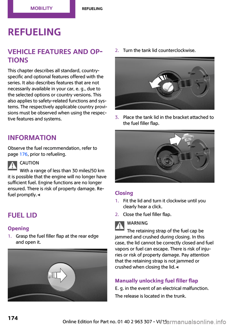
Fuel lid Opening1.Grasp the fuel filler flap at the rear edge
and open it.2.Turn the tank lid counterclockwise.3.Place the tank lid in the bracket attached to
the fuel filler flap.
Closing
1.Fit the lid and turn it clockwise until you
clearly hear a click.2.Close the fuel filler flap.
WARNING
The retaining strap of the fuel cap be
jammed and crushed during closing. In this
case, the lid cannot be correctly closed and fuel
vapors or fuel can escape. There is risk of inju‐
ries or risk of property damage. Pay attention
that the retaining strap is not jammed or
crushed when closing the lid. ◀
Manually unlocking fuel filler flap E. g. in the event of an electrical malfunction.
The release is located in the trunk.
Seite 174MOBILITYRefueling174
Online Edition for Part no. 01 40 2 963 307 - VI/15
Page 188 of 251

Continued driving with a damaged tire, refer to
page 86.
Changing run-flat tires
For your own safety, only use run-flat tires. No
spare tire is available in the case of a flat tire. A
dealer’s service center or another qualified
service center or repair shop will be glad to an‐
swer additional questions at any time.
Repairing a flat tireSafety measures▷Park the vehicle as far away as possible
from passing traffic and on solid ground.▷Switch on the hazard warning system.▷Secure the vehicle against rolling away by
setting the parking brake.▷Turn the steering wheel until the front
wheels are in the straight-ahead position
and engage the steering wheel lock.▷Have all vehicle occupants get out of the
vehicle and ensure that they remain out‐
side the immediate area in a safe place,
such as behind a guardrail.▷If necessary, set up a warning triangle at an
appropriate distance.
Mobility System
The concept
With the Mobility System, minor tire damage
can be sealed quickly to enable continued
travel. To accomplish this, sealant is pumped
into the tires, which seals the damage from the
inside.
The compressor can be used to check the tire
inflation pressure.
Information▷Follow the instructions on using the Mobi‐
lity System found on the compressor and
sealant container.▷Use of the Mobility System may be ineffec‐
tive if the tire puncture measures approx.
1/8 in/4 mm or more.▷Contact a dealer’s service center or another
qualified service center or repair shop if the
tire cannot be made drivable.▷If possible, do not remove foreign bodies
that have penetrated the tire.▷Pull the speed limit sticker off the sealant
container and apply it to the steering
wheel.▷The use of a sealant can damage the TPM
wheel electronics. In this case, have the
electronics checked at the next opportunity
and have them replaced if needed.
DANGER
If the exhaust pipe is blocked or ventila‐
tion is insufficient, harmful exhaust gases can
enter into the vehicle. The exhaust gases con‐
tain carbon monoxide, an odorless and color‐
less but highly toxic gas. In enclosed areas, ex‐
haust gases can also accumulate outside of the
vehicle. There is danger to life. Keep the ex‐
haust pipe free and ensure sufficient ventila‐
tion. ◀
Storage
The Mobility System is located under the cargo
floor panel.
Seite 188MOBILITYWheels and tires188
Online Edition for Part no. 01 40 2 963 307 - VI/15
Page 194 of 251

Hood
Information WARNING
Improperly executed work in the engine
compartment can damage components and
lead to a safety risk. There is risk of accidents or
risk of property damage. ◀
WARNING
The engine compartment accommodates
moving components. Certain components can
move in the engine compartment with the ve‐
hicle switched off, e.g. the cooler fan. There is
risk of injuries. Do not reach into the area of
moving parts. Keep articles of clothing and hair
away from moving parts. ◀
CAUTION
Folded-away wipers can be jammed
when the hood is opened. There is risk of prop‐
erty damage. Make sure that the wipers with
the wiper blades mounted are folded down onto the windshield before opening the
hood. ◀
WARNING
There are protruding parts, e.g. lock
hook, on the inside of the hood. There is risk of
injuries. If the hood is open, pay attention to
protruding parts and keep these areas clear. ◀
WARNING
An incorrectly locked hood can open
while driving and restrict visibility. There is risk
of an accident. Stop immediately and correctly
close the hood. ◀
WARNING
Body parts can be jammed on opening
and closing the hood. There is risk of injuries.
Make sure that the area of movement of the
hood is clear during opening and closing. ◀Opening the hood1.Pull lever, arrow 1.
Hood is unlocked.2.After the lever is released, pull the lever
again, arrow 2.
Hood can be opened.
Indicator/warning lights
When the hood is opened, a Check Control
message is displayed.
Closing the hood
Let the hood fall from approx. 16 in/40 cm, ar‐
row.
The hood must audibly engage on both sides.
Seite 194MOBILITYEngine compartment194
Online Edition for Part no. 01 40 2 963 307 - VI/15
Page 197 of 251
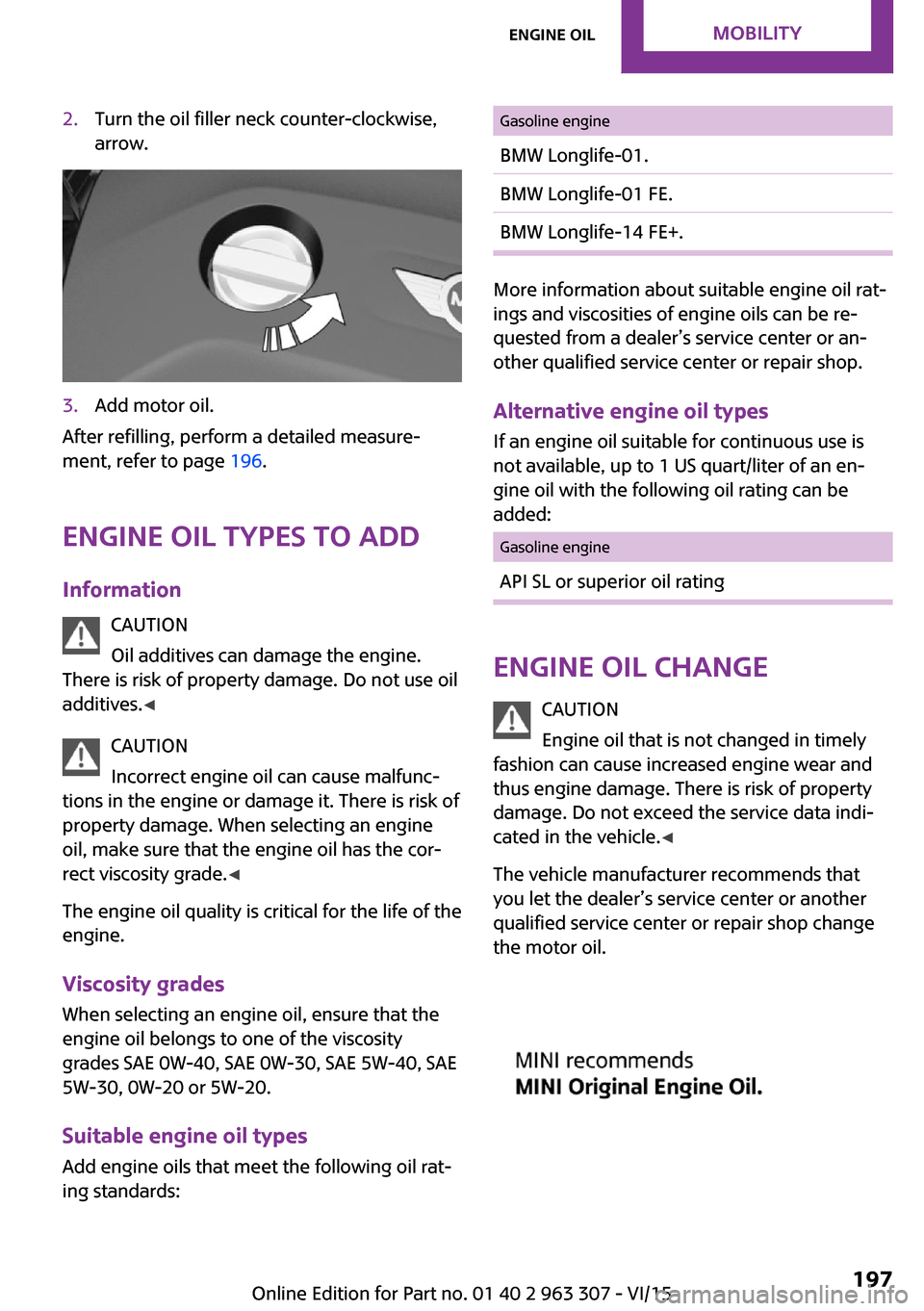
2.Turn the oil filler neck counter-clockwise,
arrow.3.Add motor oil.
After refilling, perform a detailed measure‐
ment, refer to page 196.
Engine oil types to add
Information CAUTION
Oil additives can damage the engine.
There is risk of property damage. Do not use oil
additives. ◀
CAUTION
Incorrect engine oil can cause malfunc‐
tions in the engine or damage it. There is risk of
property damage. When selecting an engine
oil, make sure that the engine oil has the cor‐
rect viscosity grade. ◀
The engine oil quality is critical for the life of the
engine.
Viscosity grades
When selecting an engine oil, ensure that the
engine oil belongs to one of the viscosity
grades SAE 0W-40, SAE 0W-30, SAE 5W-40, SAE
5W-30, 0W-20 or 5W-20.
Suitable engine oil types Add engine oils that meet the following oil rat‐
ing standards:
Gasoline engineBMW Longlife-01.BMW Longlife-01 FE.BMW Longlife-14 FE+.
More information about suitable engine oil rat‐
ings and viscosities of engine oils can be re‐
quested from a dealer’s service center or an‐
other qualified service center or repair shop.
Alternative engine oil types If an engine oil suitable for continuous use is
not available, up to 1 US quart/liter of an en‐
gine oil with the following oil rating can be
added:
Gasoline engineAPI SL or superior oil rating
Engine oil change
CAUTION
Engine oil that is not changed in timely
fashion can cause increased engine wear and
thus engine damage. There is risk of property
damage. Do not exceed the service data indi‐ cated in the vehicle. ◀
The vehicle manufacturer recommends that
you let the dealer’s service center or another
qualified service center or repair shop change
the motor oil.
Seite 197Engine oilMOBILITY197
Online Edition for Part no. 01 40 2 963 307 - VI/15
Page 198 of 251

CoolantVehicle features and op‐
tions
This chapter describes all standard, country-
specific and optional features offered with the
series. It also describes features that are not
necessarily available in your car, e. g., due to
the selected options or country versions. This
also applies to safety-related functions and sys‐
tems. The respectively applicable country provi‐
sions must be observed when using the respec‐
tive features and systems.
Information WARNING
With the engine hot and the cooling sys‐
tem open, coolant can escape and lead to
burns. There is risk of injuries. Only open the cooling system with the engine cooled down. ◀
WARNING
Additives are harmful and incorrect addi‐
tives can damage the engine. There is risk of in‐
juries and risk of property damage. Avoid the
contact of articles of clothing, skin or eyes with
additives. Do not swallow any additives. Use
suitable additives only. ◀
Coolant consists of water and additives.
Not all commercially available additives are
suitable for the vehicle. Information about suit‐
able additives is available from a dealer’s serv‐
ice center or another qualified service center or
repair shop.
Coolant level
Overview Opening the hood, refer to page 194The coolant reservoir is in the engine compart‐
ment, refer to page 193.
Checking
There are yellow Min and Max marks in the
coolant reservoir.1.Let the engine cool.2.Turn the lid of the coolant reservoir slightly
counterclockwise to allow any excess pres‐
sure to dissipate, then open it.3.The coolant level is correct if it lies between
the minimum and maximum marks in the
filler neck.Seite 198MOBILITYCoolant198
Online Edition for Part no. 01 40 2 963 307 - VI/15
Page 199 of 251
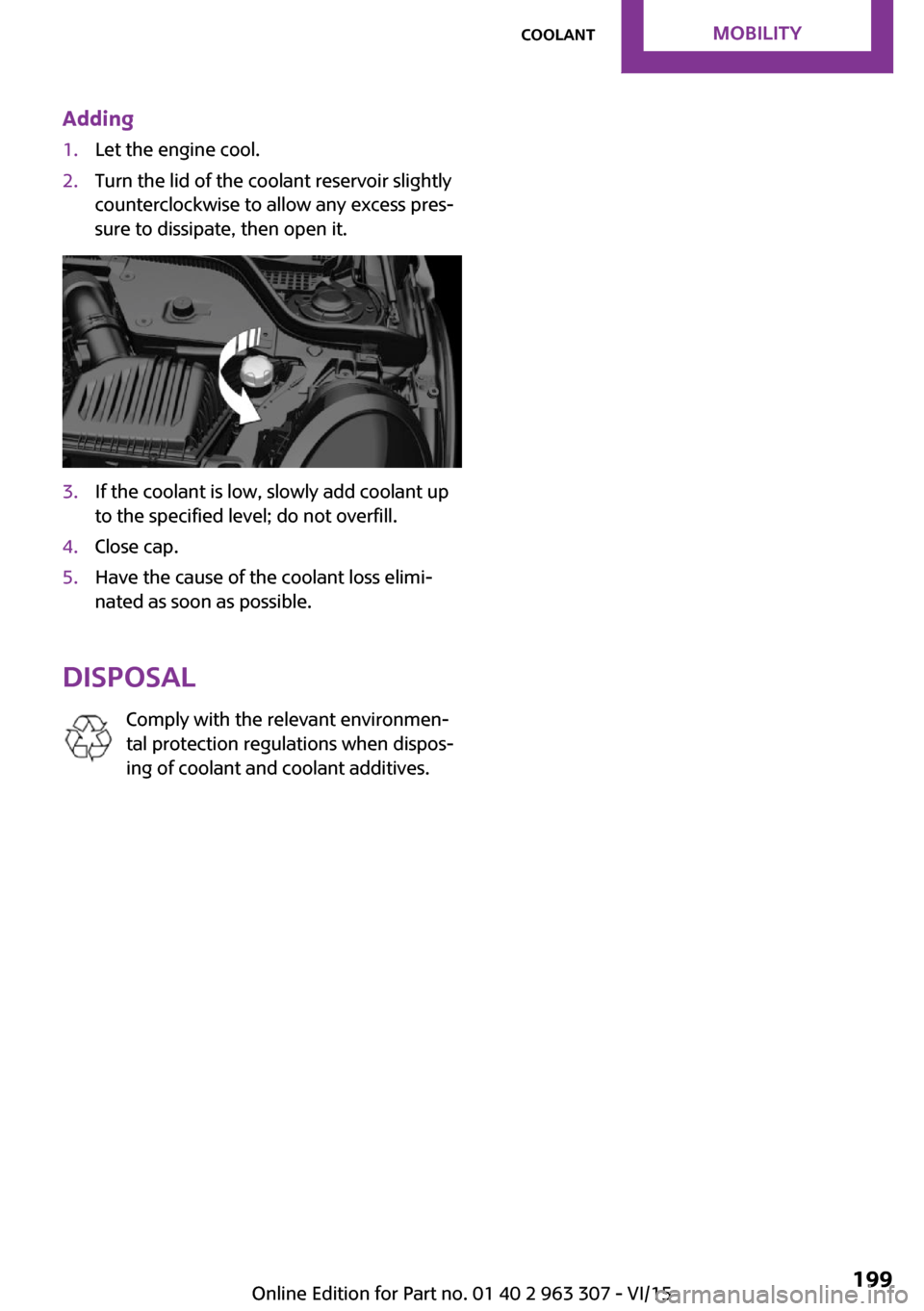
Adding1.Let the engine cool.2.Turn the lid of the coolant reservoir slightly
counterclockwise to allow any excess pres‐
sure to dissipate, then open it.3.If the coolant is low, slowly add coolant up
to the specified level; do not overfill.4.Close cap.5.Have the cause of the coolant loss elimi‐
nated as soon as possible.
Disposal
Comply with the relevant environmen‐
tal protection regulations when dispos‐
ing of coolant and coolant additives.
Seite 199CoolantMOBILITY199
Online Edition for Part no. 01 40 2 963 307 - VI/15
Page 202 of 251
Replacing componentsVehicle features and op‐
tions
This chapter describes all standard, country-
specific and optional features offered with the
series. It also describes features that are not
necessarily available in your car, e. g., due to
the selected options or country versions. This
also applies to safety-related functions and sys‐
tems. The respectively applicable country provi‐
sions must be observed when using the respec‐
tive features and systems.
Onboard vehicle tool kit
The onboard vehicle tool kit is located in the
trough under the trunk floor.
The warning triangle is located in the tailgate.
To remove, loosen the brackets.
Wiper blade replacement
Information CAUTION
If the wiper arm falls onto the windshield
without the wiper blades installed, the wind‐
shield can be damaged. There is risk of prop‐
erty damage. Secure the wiper arm when re‐
placing the wiper blades and do not fold down
the wipers without the wiper blades installed. ◀
CAUTION
Folded-away wipers can be jammed
when the hood is opened. There is risk of prop‐
erty damage. Make sure that the wipers with
the wiper blades mounted are folded down
onto the windshield before opening the
hood. ◀
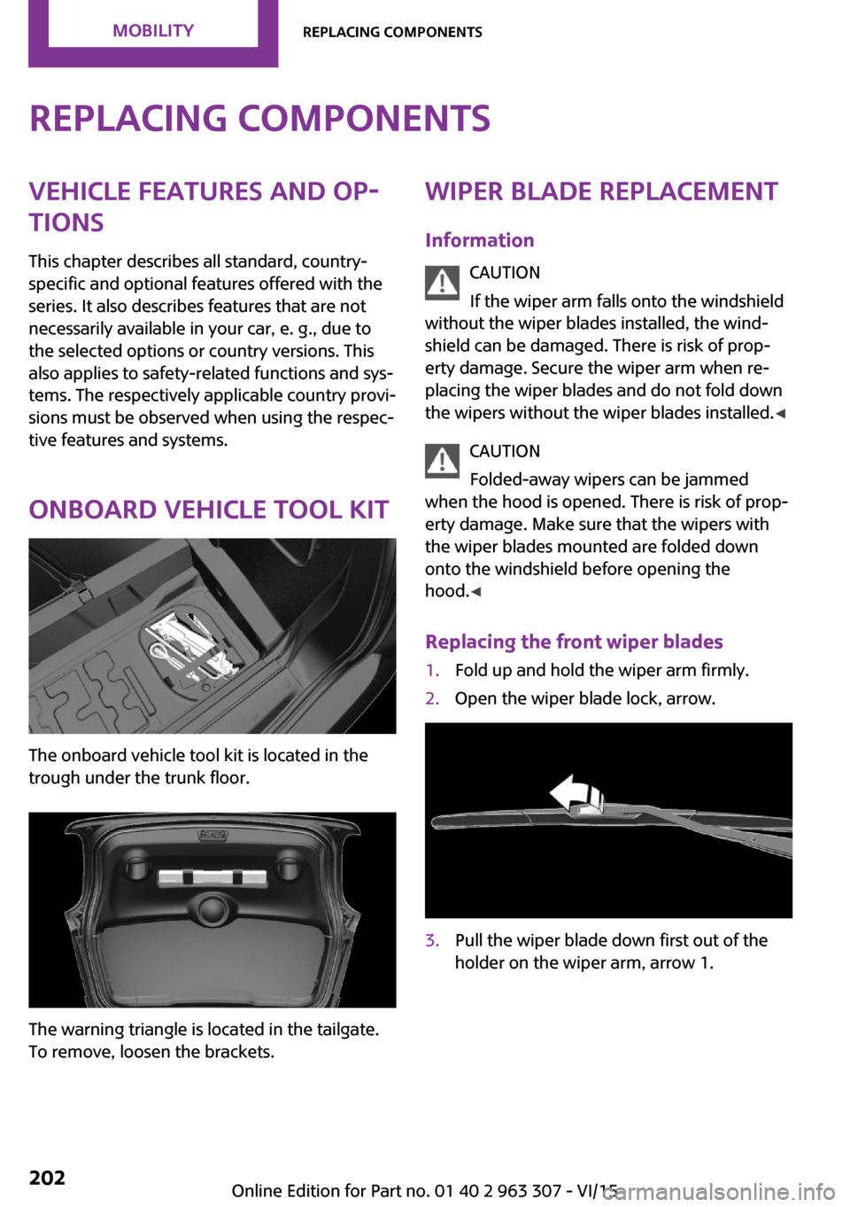
Replacing the front wiper blades1.Fold up and hold the wiper arm firmly.2.Open the wiper blade lock, arrow.3.Pull the wiper blade down first out of the
holder on the wiper arm, arrow 1.Seite 202MOBILITYReplacing components202
Online Edition for Part no. 01 40 2 963 307 - VI/15
Page 205 of 251
LED low beams/LED high beamsFollow the general instructions on lights and
bulbs, refer to page 203.
The lights feature LED technology. Contact a
dealer’s service center or another qualified
service center or repair shop in the event of a
malfunction.
Halogen low beams/halogen high
beams
Follow the general instructions on lights and
bulbs, refer to page 203.
Bulbs: H41.Open the hood, refer to page 194.2.Turn the lid counterclockwise, arrow, and
remove.3.Pull off the connector.4.Unclip spring clip, arrow, and fold down.5.Remove the bulb from the headlight hous‐
ing.6.Insert the new bulb and install the cover in
the reverse order.Turn signal
Follow the general instructions on lights and
bulbs, refer to page 203.
Bulbs: PW24W
With white turn signal lights: PWY24W1.Turn the steering wheel.2.Turn the lid counterclockwise, arrow 1, and
remove.3.Unscrew the inner lid counterclockwise,
and remove it.4.Pull bulb holder out of the bulb housing; if
needed, loosen it with small tilting move‐
ments if possible.Seite 205Replacing componentsMOBILITY205
Online Edition for Part no. 01 40 2 963 307 - VI/15
Page 206 of 251

5.Pull the bulb out of the fixture.6.Insert the new bulb and install the cover in
the reverse order.
LED parking lights/LED fog lights
Follow the general instructions on lights and
bulbs, refer to page 203.
The lights feature LED technology. Contact a
dealer’s service center or another qualified
service center or repair shop in the event of a
malfunction.
Parking lights/fog lights/daytime
running lights
Follow the general instructions on lights and
bulbs, refer to page 203.
Bulbs:
▷Parking lights for halogen headlights: W5W
Parking lights for LED headlights: W5W NBV▷Daytime running light: PSX24W▷Fog lamp: H8
Replacing the bulbs
1.Turn the steering wheel.2.Turn the lid counterclockwise, arrow 2, and
remove.3.Remove the corresponding connector.4.Remove the bulb holder.▷Turn the parking light bulb holder coun‐
ter-clockwise, arrow 1, and remove.▷Press together the upper and lower
locking of the daytime running lightsbulb holder, arrow 2, and remove the
bulb holder.
For better accessibility, if needed, re‐
move the bulb of the fog lamp before‐
hand.▷Turn the fog light bulb holder counter-
clockwise, arrow 3, and remove.5.Pull the bulb out of the fixture.6.Insert the new bulb and install the cover in
the reverse order.
The daytime running lights bulb holder en‐
gages audibly, first below, then above.
Tail lights, bulb replacement
Overview
Vehicles with a rear fog lamp
1Side tail lights2Rear fog lamp3License plate lamp4Center brake lampSeite 206MOBILITYReplacing components206
Online Edition for Part no. 01 40 2 963 307 - VI/15
Page 207 of 251

Vehicle with two rear fog lights1Side tail lights2Rear fog lights3License plate lamp4Center brake lamp
Side tail lights
1Brake lights/tail lights2Turn signal3Reversing lights
Side LED tail lights
1Tail lights2Turn signal3Brake light4Reversing lights
Side tail lights
Follow the general instructions on lights and
bulbs, refer to page 203.
Bulbs: P21W
1.Open tailgate, refer to page 27.2.Remove left or right cover.3.Through the opening, loosen the plug con‐
nector, arrow 2 on the bulb holder.
Press the latches together, arrows 1, and
remove the bulb holder.4.Remove the bulb holder from the opening.5.Press the nonworking bulb gently into the
socket, turn counterclockwise and remove.▷Arrow 1: brake lights/tail lights▷Arrow 2: turn signalSeite 207Replacing componentsMOBILITY207
Online Edition for Part no. 01 40 2 963 307 - VI/15