ESP MINI Hardtop 4 Door 2016 Manual Online
[x] Cancel search | Manufacturer: MINI, Model Year: 2016, Model line: Hardtop 4 Door, Model: MINI Hardtop 4 Door 2016Pages: 251, PDF Size: 6.71 MB
Page 204 of 251

Headlight glass
Condensation can form on the inside of the ex‐
ternal lights in cool or humid weather. When
driving with the lights switched on, the conden‐
sation evaporates after a short time. The head‐
light glass does not need to be changed.
If despite driving with the lights switched on,
increasing humidity forms, e. g. water droplets
in the lamp, the manufacturer of your vehicle
recommends having it checked by a dealer’s
service center or another qualified service cen‐
ter or repair shop.
Front lights, bulb replacement
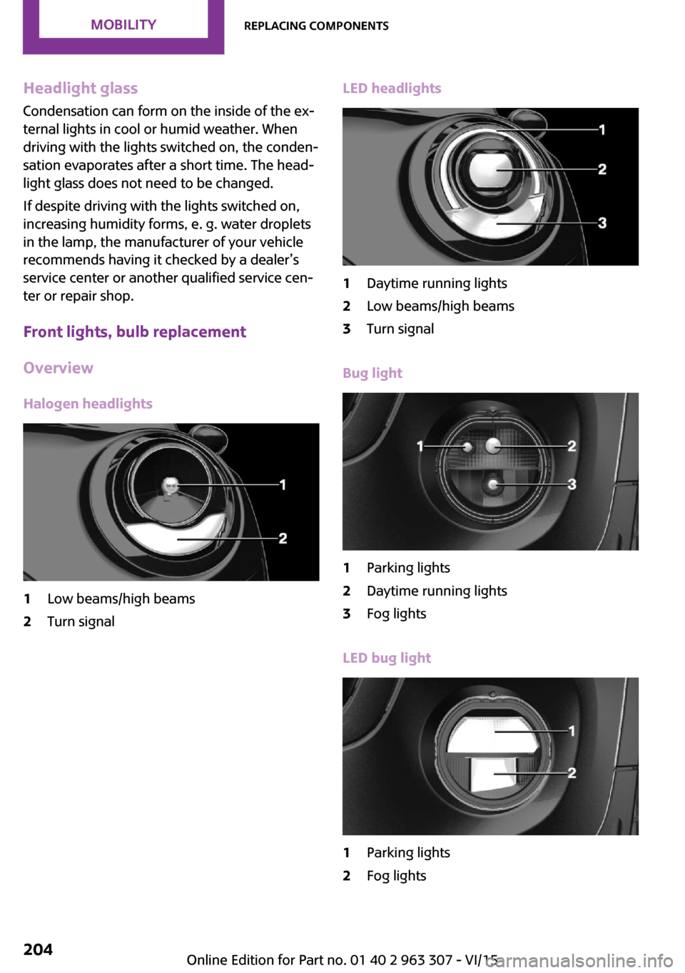
Overview Halogen headlights1Low beams/high beams2Turn signalLED headlights1Daytime running lights2Low beams/high beams3Turn signal
Bug light
1Parking lights2Daytime running lights3Fog lights
LED bug light
1Parking lights2Fog lightsSeite 204MOBILITYReplacing components204
Online Edition for Part no. 01 40 2 963 307 - VI/15
Page 206 of 251

5.Pull the bulb out of the fixture.6.Insert the new bulb and install the cover in
the reverse order.
LED parking lights/LED fog lights
Follow the general instructions on lights and
bulbs, refer to page 203.
The lights feature LED technology. Contact a
dealer’s service center or another qualified
service center or repair shop in the event of a
malfunction.
Parking lights/fog lights/daytime
running lights
Follow the general instructions on lights and
bulbs, refer to page 203.
Bulbs:
▷Parking lights for halogen headlights: W5W
Parking lights for LED headlights: W5W NBV▷Daytime running light: PSX24W▷Fog lamp: H8
Replacing the bulbs
1.Turn the steering wheel.2.Turn the lid counterclockwise, arrow 2, and
remove.3.Remove the corresponding connector.4.Remove the bulb holder.▷Turn the parking light bulb holder coun‐
ter-clockwise, arrow 1, and remove.▷Press together the upper and lower
locking of the daytime running lightsbulb holder, arrow 2, and remove the
bulb holder.
For better accessibility, if needed, re‐
move the bulb of the fog lamp before‐
hand.▷Turn the fog light bulb holder counter-
clockwise, arrow 3, and remove.5.Pull the bulb out of the fixture.6.Insert the new bulb and install the cover in
the reverse order.
The daytime running lights bulb holder en‐
gages audibly, first below, then above.
Tail lights, bulb replacement
Overview
Vehicles with a rear fog lamp
1Side tail lights2Rear fog lamp3License plate lamp4Center brake lampSeite 206MOBILITYReplacing components206
Online Edition for Part no. 01 40 2 963 307 - VI/15
Page 214 of 251

Breakdown assistanceVehicle features and op‐
tions
This chapter describes all standard, country-
specific and optional features offered with the
series. It also describes features that are not
necessarily available in your car, e. g., due to
the selected options or country versions. This
also applies to safety-related functions and sys‐
tems. The respectively applicable country provi‐
sions must be observed when using the respec‐
tive features and systems.
Hazard warning flash‐
ers
The button is located above the radio.
Warning triangle
The warning triangle is located in the tailgate.
To remove, loosen the brackets.
First-aid kit
The first-aid kit is located in the trunk.
Some of the articles have a limited service life.
Check the expiration dates of the contents reg‐
ularly and replace any expired items promptly.
Jump-starting General information If the battery is discharged, the engine can be
started using the battery of another vehicle and
two jumper cables. Only use jumper cables with
fully insulated clamp handles.
Information DANGER
Contact with live components can lead to
an electric shock. There is risk of injuries or
danger to life. Do not touch any components
that are under voltage. ◀
To prevent personal injury or damage to both
vehicles, adhere strictly to the following proce‐
dure.
Seite 214MOBILITYBreakdown assistance214
Online Edition for Part no. 01 40 2 963 307 - VI/15
Page 215 of 251

PreparationCAUTION
In the case of body contact between the
two vehicles, a short circuit can occur during
jump-starting. There is risk of property damage.
Make sure that no body contact occurs. ◀1.Check whether the battery of the other ve‐
hicle has a voltage of 12 volts. This informa‐
tion can be found on the battery.2.Switch off the engine of the assisting vehi‐
cle.3.Switch off any electronic systems/power
consumers in both vehicles.
Starting aid terminals
WARNING
If the jumper cables are connected in the
incorrect order, sparks formation can occur.
There is risk of injuries. Pay attention to the cor‐
rect order during connection. ◀
The so-called starting aid terminal in the engine
compartment acts as the battery's positive ter‐
minal.
Open the lid of the starting aid terminal.
The body ground acts as the negative terminal
of the battery.
Connecting the cables
1.Pull off the lid of the starting aid terminal.2.Attach one terminal clamp of the positive
jumper cable to the positive terminal of the
battery, or to the corresponding starting aid
terminal of the vehicle providing assistance.3.Attach the terminal clamp on the other end
of the cable to the positive terminal of the
battery, or to the corresponding starting aid
terminal of the vehicle to be started.4.Attach one terminal clamp of the negative
jumper cable to the negative terminal of
the battery, or to the corresponding engine
or body ground of assisting vehicle.5.Attach the second terminal clamp to the
negative terminal of the battery, or to the
corresponding engine or body ground of
the vehicle to be started.
Starting the engine
Never use spray fluids to start the engine.
1.Start the engine of the assisting vehicle and
let it run for several minutes at an increased
idle speed.2.Start the engine of the vehicle that is to be
started in the usual way.
If the first starting attempt is not successful,
wait a few minutes before making another
attempt in order to allow the discharged
battery to recharge.Seite 215Breakdown assistanceMOBILITY215
Online Edition for Part no. 01 40 2 963 307 - VI/15
Page 218 of 251

Tow fitting
General information
The screw-in tow fitting should always be car‐
ried in the vehicle.
The tow fitting can be screwed in at the front or
rear of the MINI.
The tow fitting and the onboard vehicle tool kit,
refer to page 202, are together in the cargo
area.
Information CAUTION
If the tow fitting is not used as intended,
there can be damage to the vehicle or to the
tow fitting. There is risk of property damage.
Observe the notes on using the tow fitting. ◀
Use of the tow fitting:
▷Use only the tow fitting provided with the
vehicle and screw it all the way in.▷Use the tow fitting for towing on paved
roads only.▷Use tow fitting located in the front only for
positioning the vehicle.▷Avoid lateral loading of the tow fitting, e.g.,
do not lift the vehicle by the tow fitting.Screw thread for tow fitting
COOPER/COOPER D
ONE/ONE D
COOPER S/COOPER SD
JOHN COOPER WORKS
Threaded holes for the tow fitting are located in
the front and rear of the vehicle on the right
side with respect to the direction of travel.
Push out the cover by pressing on the top edge.
Tow-starting
Steptronic transmission Do not tow-start the vehicle.
Seite 218MOBILITYBreakdown assistance218
Online Edition for Part no. 01 40 2 963 307 - VI/15
Page 220 of 251

CareVehicle features and op‐tions
This chapter describes all standard, country-
specific and optional features offered with the series. It also describes features that are not
necessarily available in your car, e. g., due to
the selected options or country versions. This
also applies to safety-related functions and sys‐
tems. The respectively applicable country provi‐
sions must be observed when using the respec‐
tive features and systems.
Car washes
General information Regularly remove foreign objects such as leaves
in the area below the windshield when the
hood is raised.
Wash your vehicle frequently, particularly in
winter. Intense soiling and road salt can dam‐
age the vehicle.
Steam jets or high-pressure washers
Information CAUTION
When cleaning with high-pressure wash‐
ers, components can be damaged due to the
pressure or temperatures being too high. There
is risk of property damage. Maintain sufficient
distance and do not spray too long continu‐
ously. Follow the user's manual for the high-
pressure washer. ◀
Distances and temperature▷Maximum temperature: 140 ℉/60 ℃.▷Minimum distance from sensors, cameras,
seals: 12 in/30 cm.▷Minimum distance from glass sunroof:
31.5 inches/80 cm.
Automatic car washes
Information
▷Give preference to cloth car washes or
those that use soft brushes in order to
avoid paint damage.▷Make sure that the wheels and tires are not
damaged by the transport mechanisms.▷Fold in the exterior mirrors; otherwise, they
may be damaged, depending on the width
of the vehicle.▷Unscrew the rod antenna.▷Deactivate the rain sensor, refer to
page 56, to avoid unintentional wiper acti‐
vation.▷In some cases, an unintentional alarm can
be triggered by the interior motion sensor
of the alarm system. Follow the instructions
on avoiding an unintentional alarm, refer to
page 31.
CAUTION
Too high guide rails in car washes can
damage body parts. There is risk of property
damage. Avoid car washes with guide rails
higher than 4 in/10 cm. ◀
Before driving into a car wash
In order to ensure that the vehicle can roll in a
car wash, take the following steps:
Manual transmission:
1.Drive into the car wash.2.Shift to neutral.3.Switch the engine off.4.Switch on the ignition.Seite 220MOBILITYCare220
Online Edition for Part no. 01 40 2 963 307 - VI/15
Page 222 of 251

Use leather care products; otherwise, dirt and
grease will gradually break down the protective
layer of the leather surface.
Suitable care products are available from a
dealer’s service center or another qualified
service center or repair shop.
Upholstery material care
Vacuum regularly with a vacuum cleaner.
If upholstery is very dirty, e.g., with beverage
stains, use a soft sponge or microfiber cloth
with a suitable interior cleaner.
Clean the upholstery down to the seams using
large sweeping motions. Avoid rubbing the ma‐
terial vigorously.
CAUTION
Open Velcro® fasteners on articles of
clothing can damage the seat covers. There is
risk of property damage. Ensure that any Vel‐
cro® fasteners are closed. ◀
Caring for special components
Light-alloy wheels
When cleaning the vehicle, use only neutral
wheel cleaners having a pH value from 5 to 9.
Do not use abrasive cleaning agents or steam
jets above 140 ℉/60 ℃. Follow the manufac‐
turer's instructions.
Aggressive, acidic or alkaline cleaning agents can destroy the protective layer of adjacent
components, such as the brake disk.
Chrome surfaces
Carefully clean components such as the radia‐
tor grille or door handles with an ample supply
of water, possibly with shampoo added, partic‐
ularly when they have been exposed to road
salt.
Rubber components Environmental influences can cause surface
soiling of rubber parts and a loss of gloss. Forcleaning, use only water and suitable care
products, the manufacturer of your vehicle rec‐
ommends original MINI care products.
Treat especially worn rubber parts with rubber
care agents at regular intervals. When cleaning
rubber seals, do not use any silicon-containing
car care products in order to avoid damage or
noises.
Fine wood parts Clean fine wood facing and fine wood compo‐
nents only with a moist rag. Then dry with a
soft cloth.
Plastic components These include:▷Imitation leather surfaces.▷Roofliner.▷Lamp lenses.▷Instrument cluster cover.▷Matt black spray-coated components.▷Painted parts in the interior.
Clean with a microfiber cloth.
Dampen cloth lightly with water.
Do not soak the roofliner.
CAUTION
Cleansers that contain alcohol or solvents,
such as lacquer thinners, heavy-duty grease re‐
movers, fuel, or such, can damage plastic parts.
There is risk of property damage. Clean with a
microfiber cloth. Dampen cloth lightly with wa‐
ter. ◀
Safety belts
Dirty belt straps impede the reeling action and
thus have a negative impact on safety.
WARNING
Chemical cleansers can destroy the safety
belt webbing. Missing protective effect of the
safety belts. There is risk of injuries or danger to
Seite 222MOBILITYCare222
Online Edition for Part no. 01 40 2 963 307 - VI/15
Page 226 of 251

Technical dataVehicle features and op‐
tions
This chapter describes all standard, country-
specific and optional features offered with the
series. It also describes features that are not
necessarily available in your car, e. g., due to
the selected options or country versions. This
also applies to safety-related functions and sys‐
tems. The respectively applicable country provi‐
sions must be observed when using the respec‐
tive features and systems.
Information
The technical data and specifications in this
Owner's Manual are used as guidance values.
The vehicle-specific data can deviate from this,
for example, due to the selected special equip‐
ment, country version or country-specific
measurement method. Detailed values can be
found in the approval documents, on labels on
the vehicle or can be obtained from a dealer’s
service center or another qualified service cen‐
ter or repair shop.
The information in the vehicle documents al‐
ways has priority.
Dimensions
The dimensions can vary depending on the
model version, equipment or country-specific
measurement method.
The specified heights do not take into account
attached parts, for example, a roof antenna,
roof racks or spoiler. The heights can deviate,
for example, due to the selected special equip‐
ment, tires, load and chassis version.
Seite 226REFERENCETechnical data226
Online Edition for Part no. 01 40 2 963 307 - VI/15
MINI 3-doorWidth with mirrorsinches/mm76.1/1,932Width without mirrorsinches/mm68.0/1,727Heightinches/mm55.7/1,414LengthCooperinches/mm151.1/3,837Cooper Sinches/mm151.9/3,858John Cooper Worksinches/mmWheelbaseinches/mm98.2/2,495Smallest turning radius diam.ft/m35.4/10.8152.5/3,874
Page 235 of 251

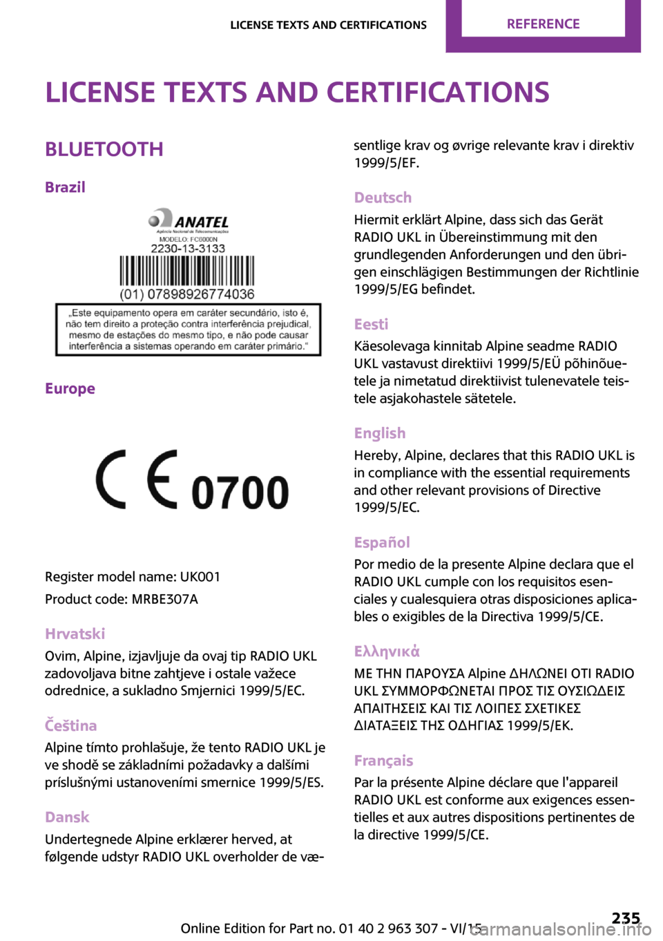
License Texts and CertificationsBluetoothBrazil
Europe
Register model name: UK001
Product code: MRBE307A
Hrvatski
Ovim, Alpine, izjavljuje da ovaj tip RADIO UKL
zadovoljava bitne zahtjeve i ostale važece
odrednice, a sukladno Smjernici 1999/5/EC.
Čeština
Alpine tímto prohlašuje, že tento RADIO UKL je
ve shodě se základními požadavky a dalšími
príslušnými ustanoveními smernice 1999/5/ES.
Dansk Undertegnede Alpine erklærer herved, at
følgende udstyr RADIO UKL overholder de væ‐
sentlige krav og øvrige relevante krav i direktiv
1999/5/EF.
Deutsch
Hiermit erklärt Alpine, dass sich das Gerät
RADIO UKL in Übereinstimmung mit den
grundlegenden Anforderungen und den übri‐ gen einschlägigen Bestimmungen der Richtlinie
1999/5/EG befindet.
Eesti Käesolevaga kinnitab Alpine seadme RADIO
UKL vastavust direktiivi 1999/5/EÜ põhinõue‐
tele ja nimetatud direktiivist tulenevatele teis‐
tele asjakohastele sätetele.
English Hereby, Alpine, declares that this RADIO UKL is
in compliance with the essential requirements
and other relevant provisions of Directive
1999/5/EC.
Español
Por medio de la presente Alpine declara que el
RADIO UKL cumple con los requisitos esen‐
ciales y cualesquiera otras disposiciones aplica‐
bles o exigibles de la Directiva 1999/5/CE.
Ελληνικά
ΜΕ ΤΗΝ ΠΑΡΟΥΣΑ Alpine ∆ΗΛΩΝΕΙ ΟΤΙ RADIO
UKL ΣΥΜΜΟΡΦΩΝΕΤΑΙ ΠΡΟΣ ΤΙΣ ΟΥΣΙΩ∆ΕΙΣ ΑΠΑΙΤΗΣΕΙΣ ΚΑΙ ΤΙΣ ΛΟΙΠΕΣ ΣΧΕΤΙΚΕΣ
∆ΙΑΤΑΞΕΙΣ ΤΗΣ Ο∆ΗΓΙΑΣ 1999/5/ΕΚ.
Français
Par la présente Alpine déclare que l'appareil
RADIO UKL est conforme aux exigences essen‐
tielles et aux autres dispositions pertinentes de
la directive 1999/5/CE.Seite 235License Texts and CertificationsREFERENCE235
Online Edition for Part no. 01 40 2 963 307 - VI/15
Page 237 of 251

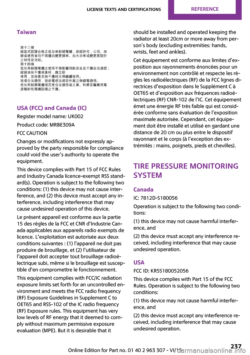
Taiwan
USA (FCC) and Canada (IC)
Register model name: UK002
Product code: MRBE309A
FCC CAUTION
Changes or modifications not expressly ap‐
proved by the party responsible for compliance
could void the user’s authority to operate the
equipment.
This device complies with Part 15 of FCC Rules
and Industry Canada licence-exempt RSS stand‐
ard(s). Operation is subject to the following two
conditions: (1) this device may not cause inter‐
ference, and (2) this device must accept any in‐
terference, including interference that may
cause undesired operation of this device.
Le présent appareil est conforme aux la partie
15 des règles de la FCC et CNR d'Industrie Can‐
ada applicables aux appareils radio exempts de
licence. L'exploitation est autorisée aux deux
conditions suivantes : (1) l'appareil ne doit pas
produire de brouillage, et (2) l'utilisateur de
l'appareil doit accepter tout brouillage radioé‐
lectrique subi, même si le brouillage est suscep‐
tible d'en compromettre le fonctionnement.
This equipment complies with FCC/IC radiation
exposure limits set forth for an uncontrolled en‐
vironment and meets the FCC radio frequency
(RF) Exposure Guidelines in Supplement C to
OET65 and RSS-102 of the IC radio frequency
(RF) Exposure rules. This equipment has very
low levels of RF energy that it deemed to com‐
ply without maximum permissive exposure
evaluation (MPE). But it is desirable that it
should be installed and operated keeping the
radiator at least 20cm or more away from per‐
son’s body (excluding extremities: hands,
wrists, feet and ankles).
Cet équipement est conforme aux limites d’ex‐
position aux rayonnements énoncées pour un
environnement non contrôlé et respecte les rè‐
gles les radioélectriques (RF) de la FCC lignes di‐
rectrices d'exposition dans le Supplément C à
OET65 et d’exposition aux fréquences radioé‐
lectriques (RF) CNR-102 de l’IC. Cet équipement
émet une énergie RF très faible qui est consid‐
érée conforme sans évaluation de l’exposition
maximale autorisée. Cependant, cet équipe‐
ment doit être installé et utilisé en gardant une
distance de 20 cm ou plus entre le dispositif
rayonnant et le corps (à l’exception des ex‐
trémités : mains, poignets, pieds et chevilles).
Tire Pressure Monitoring
System
Canada
IC: 7812D-S180056
Operation is subject to the following two condi‐
tions:
(1) this device may not cause harmful interfer‐
ence, and
(2) this device must accept any interference re‐
ceived, including interference that may cause undesired operation.
USA FCC ID: KR5S180052056
This device complies with Part 15 of the FCC
Rules. Operation is subject to the following two
conditions:
(1) this device may not cause harmful interfer‐
ence, and
(2) this device must accept any interference re‐
ceived, including interference that may cause undesired operation.Seite 237License Texts and CertificationsREFERENCE237
Online Edition for Part no. 01 40 2 963 307 - VI/15