clock MINI Hardtop 4 Door 2016 Owner's Manual
[x] Cancel search | Manufacturer: MINI, Model Year: 2016, Model line: Hardtop 4 Door, Model: MINI Hardtop 4 Door 2016Pages: 251, PDF Size: 6.71 MB
Page 19 of 251
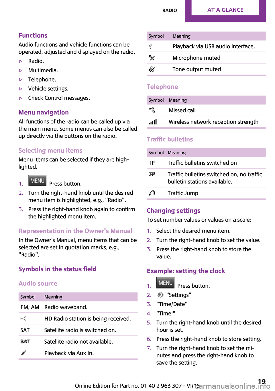
FunctionsAudio functions and vehicle functions can be
operated, adjusted and displayed on the radio.▷Radio.▷Multimedia.▷Telephone.▷Vehicle settings.▷Check Control messages.
Menu navigation
All functions of the radio can be called up via
the main menu. Some menus can also be called
up directly via the buttons on the radio.
Selecting menu items
Menu items can be selected if they are high‐
lighted.
1. Press button.2.Turn the right-hand knob until the desired
menu item is highlighted, e.g., "Radio".3.Press the right-hand knob again to confirm
the highlighted menu item.
Representation in the Owner's Manual
In the Owner's Manual, menu items that can be
selected are set in quotation marks, e.g.,
"Radio".
Symbols in the status field
Audio source
SymbolMeaningFM, AMRadio waveband. HD Radio station is being received.SATSatellite radio is switched on. Satellite radio not available. Playback via Aux In.SymbolMeaning Playback via USB audio interface. Microphone muted Tone output muted
Telephone
SymbolMeaning Missed call Wireless network reception strength
Traffic bulletins
SymbolMeaningTPTraffic bulletins switched on Traffic bulletins switched on, no traffic
bulletin stations available. Traffic Jump
Changing settings
To set number values or values on a scale:
1.Select the desired menu item.2.Turn the right-hand knob to set the value.3.Press the right-hand knob to store the
value.
Example: setting the clock
1. Press button.2. "Settings"3."Time/Date"4."Time:"5.Turn the right-hand knob until the desired
hour is set.6.Press the right-hand knob to store setting.7.Turn the right-hand knob to set the mi‐
nutes and press the right-hand knob to
save the setting.Seite 19RadioAT A GLANCE19
Online Edition for Part no. 01 40 2 963 307 - VI/15
Page 82 of 251

Ejection MitigationThe head airbag system is designed as an ejec‐
tion mitigation countermeasure to reduce the
likelihood of ejections of vehicle occupants
through side windows during rollovers or side
impact events.
Knee airbag
The knee airbag supports the legs in a frontal
impact.
Protective action
Airbags are not triggered in every impact situa‐
tion, e.g., in less severe accidents or rear-end
collisions.
Information for optimum effect of the
airbags
WARNING
If the seat position is incorrect or the de‐
ployment area of the airbags is impacted, the
airbag system cannot protect as intended or
cause additional injuries due to triggering.
There is risk of injuries or danger to life. Ob‐
serve the Information for optimum protective
effect of the airbag system. ◀▷Keep at a distance from the airbags.▷Make sure that occupants keep their heads
away from the side airbag.▷Always grasp the steering wheel on the
steering wheel rim. Hold your hands at the
3 o'clock and 9 o'clock positions, to keep
the risk of injury to your hands or arms as
low as possible when the airbag is trig‐
gered.▷Make sure that the front passenger is sitting
correctly, i.e., keeps his or her feet and legs
in the floor area.▷There should be no persons, animals or ob‐
jects between an airbag and a person.▷Do not apply adhesive materials to the air‐
bag cover panels, do not cover them or
modify them in any way.▷Dashboard and windshield on the front
passenger side must stay clear - do not at‐
tach adhesive labels or coverings and do
not attach brackets or cables, e. g., for GPS
devices or' mobile phones.▷Do not use the cover of the front airbag on
the front passenger side as a storage area.▷Do not place slip covers, seat cushions or
other objects on the front passenger seat
that are not specifically suited for seats with
integrated side airbags.▷Do not hang pieces of clothing, such as
jackets, over the backrests.▷Never modify either the individual compo‐
nents or the wiring in the airbag system.
This also applies to steering wheel covers,
the dashboard, and the seats.▷Do not remove the airbag system.
Even when you follow all instructions very
closely, injury from contact with the airbags
cannot be ruled out in certain situations.
The ignition and inflation noise may lead to
short-term and, in most cases, temporary hear‐
ing impairment in sensitive individuals.
Warnings and information on the airbags are
also found on the sun visors.
Functional readiness of the airbag
system
Information WARNING
Individual components can be hot after
triggering of the airbag system. There is risk of
injuries. Do not touch individual components. ◀
WARNING
Improperly executed work can lead to
failure, malfunction or unintentional triggering
of the airbag system. In the case of a malfunc‐
Seite 82CONTROLSSafety82
Online Edition for Part no. 01 40 2 963 307 - VI/15
Page 174 of 251
RefuelingVehicle features and op‐
tions
This chapter describes all standard, country-
specific and optional features offered with the
series. It also describes features that are not necessarily available in your car, e. g., due to
the selected options or country versions. This
also applies to safety-related functions and sys‐
tems. The respectively applicable country provi‐
sions must be observed when using the respec‐
tive features and systems.
Information Observe the fuel recommendation, refer to
page 176, prior to refueling.
CAUTION
With a range of less than 30 miles/50 km
it is possible that the engine will no longer have
sufficient fuel. Engine functions are no longer
ensured. There is risk of property damage. Re‐
fuel promptly. ◀
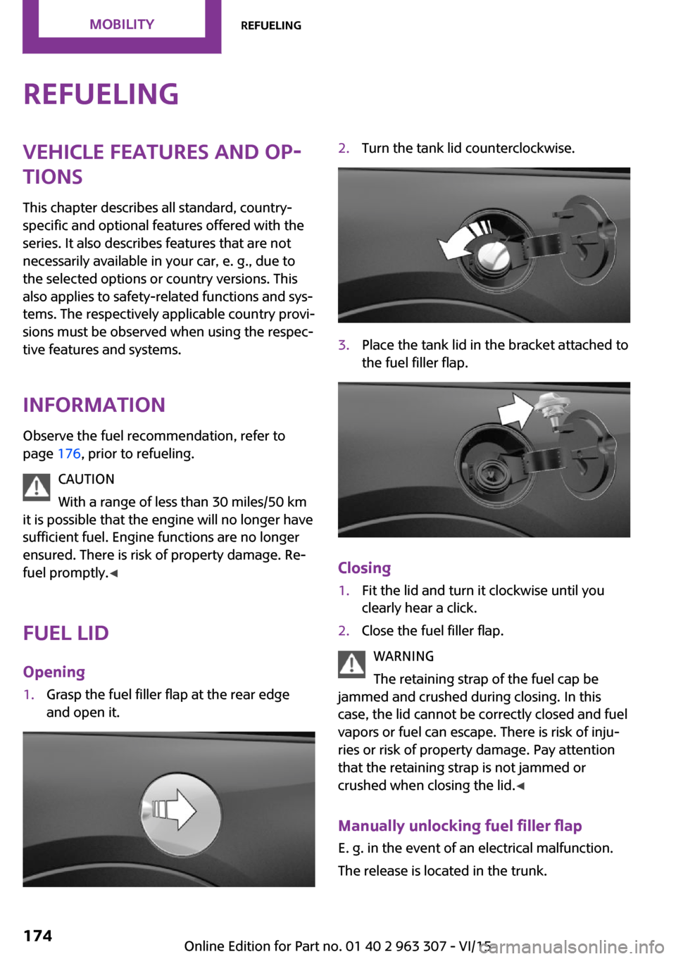
Fuel lid Opening1.Grasp the fuel filler flap at the rear edge
and open it.2.Turn the tank lid counterclockwise.3.Place the tank lid in the bracket attached to
the fuel filler flap.
Closing
1.Fit the lid and turn it clockwise until you
clearly hear a click.2.Close the fuel filler flap.
WARNING
The retaining strap of the fuel cap be
jammed and crushed during closing. In this
case, the lid cannot be correctly closed and fuel
vapors or fuel can escape. There is risk of inju‐
ries or risk of property damage. Pay attention
that the retaining strap is not jammed or
crushed when closing the lid. ◀
Manually unlocking fuel filler flap E. g. in the event of an electrical malfunction.
The release is located in the trunk.
Seite 174MOBILITYRefueling174
Online Edition for Part no. 01 40 2 963 307 - VI/15
Page 197 of 251
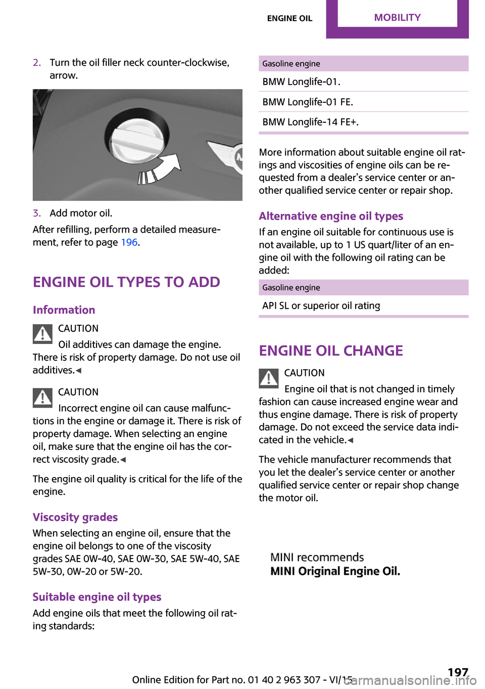
2.Turn the oil filler neck counter-clockwise,
arrow.3.Add motor oil.
After refilling, perform a detailed measure‐
ment, refer to page 196.
Engine oil types to add
Information CAUTION
Oil additives can damage the engine.
There is risk of property damage. Do not use oil
additives. ◀
CAUTION
Incorrect engine oil can cause malfunc‐
tions in the engine or damage it. There is risk of
property damage. When selecting an engine
oil, make sure that the engine oil has the cor‐
rect viscosity grade. ◀
The engine oil quality is critical for the life of the
engine.
Viscosity grades
When selecting an engine oil, ensure that the
engine oil belongs to one of the viscosity
grades SAE 0W-40, SAE 0W-30, SAE 5W-40, SAE
5W-30, 0W-20 or 5W-20.
Suitable engine oil types Add engine oils that meet the following oil rat‐
ing standards:
Gasoline engineBMW Longlife-01.BMW Longlife-01 FE.BMW Longlife-14 FE+.
More information about suitable engine oil rat‐
ings and viscosities of engine oils can be re‐
quested from a dealer’s service center or an‐
other qualified service center or repair shop.
Alternative engine oil types If an engine oil suitable for continuous use is
not available, up to 1 US quart/liter of an en‐
gine oil with the following oil rating can be
added:
Gasoline engineAPI SL or superior oil rating
Engine oil change
CAUTION
Engine oil that is not changed in timely
fashion can cause increased engine wear and
thus engine damage. There is risk of property
damage. Do not exceed the service data indi‐ cated in the vehicle. ◀
The vehicle manufacturer recommends that
you let the dealer’s service center or another
qualified service center or repair shop change
the motor oil.
Seite 197Engine oilMOBILITY197
Online Edition for Part no. 01 40 2 963 307 - VI/15
Page 198 of 251

CoolantVehicle features and op‐
tions
This chapter describes all standard, country-
specific and optional features offered with the
series. It also describes features that are not
necessarily available in your car, e. g., due to
the selected options or country versions. This
also applies to safety-related functions and sys‐
tems. The respectively applicable country provi‐
sions must be observed when using the respec‐
tive features and systems.
Information WARNING
With the engine hot and the cooling sys‐
tem open, coolant can escape and lead to
burns. There is risk of injuries. Only open the cooling system with the engine cooled down. ◀
WARNING
Additives are harmful and incorrect addi‐
tives can damage the engine. There is risk of in‐
juries and risk of property damage. Avoid the
contact of articles of clothing, skin or eyes with
additives. Do not swallow any additives. Use
suitable additives only. ◀
Coolant consists of water and additives.
Not all commercially available additives are
suitable for the vehicle. Information about suit‐
able additives is available from a dealer’s serv‐
ice center or another qualified service center or
repair shop.
Coolant level
Overview Opening the hood, refer to page 194The coolant reservoir is in the engine compart‐
ment, refer to page 193.
Checking
There are yellow Min and Max marks in the
coolant reservoir.1.Let the engine cool.2.Turn the lid of the coolant reservoir slightly
counterclockwise to allow any excess pres‐
sure to dissipate, then open it.3.The coolant level is correct if it lies between
the minimum and maximum marks in the
filler neck.Seite 198MOBILITYCoolant198
Online Edition for Part no. 01 40 2 963 307 - VI/15
Page 199 of 251
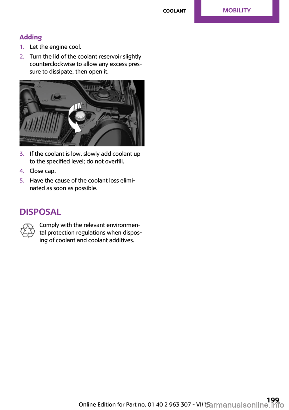
Adding1.Let the engine cool.2.Turn the lid of the coolant reservoir slightly
counterclockwise to allow any excess pres‐
sure to dissipate, then open it.3.If the coolant is low, slowly add coolant up
to the specified level; do not overfill.4.Close cap.5.Have the cause of the coolant loss elimi‐
nated as soon as possible.
Disposal
Comply with the relevant environmen‐
tal protection regulations when dispos‐
ing of coolant and coolant additives.
Seite 199CoolantMOBILITY199
Online Edition for Part no. 01 40 2 963 307 - VI/15
Page 205 of 251
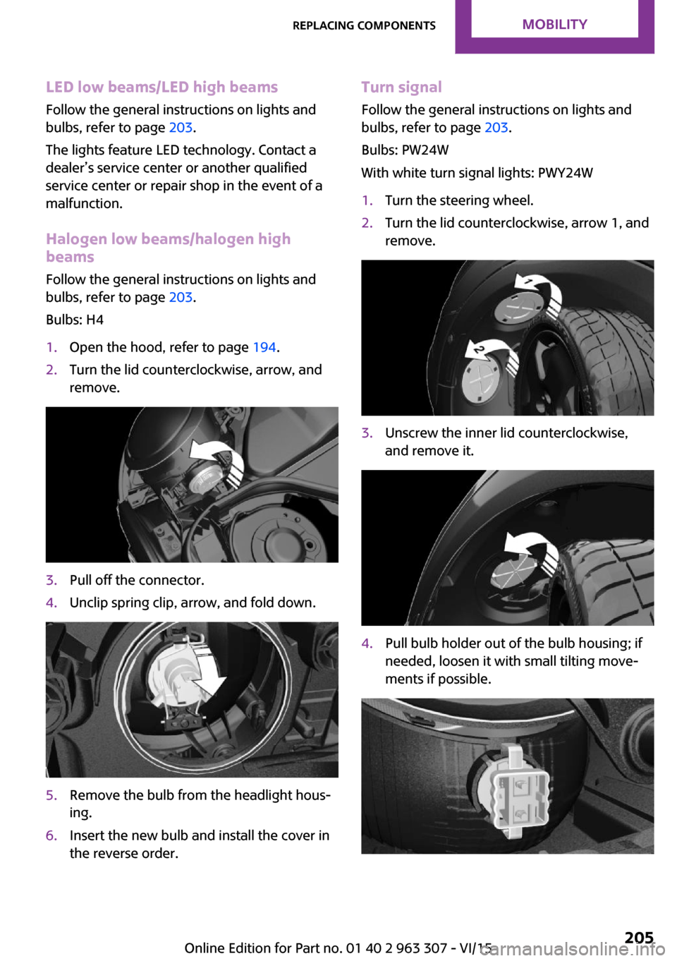
LED low beams/LED high beamsFollow the general instructions on lights and
bulbs, refer to page 203.
The lights feature LED technology. Contact a
dealer’s service center or another qualified
service center or repair shop in the event of a
malfunction.
Halogen low beams/halogen high
beams
Follow the general instructions on lights and
bulbs, refer to page 203.
Bulbs: H41.Open the hood, refer to page 194.2.Turn the lid counterclockwise, arrow, and
remove.3.Pull off the connector.4.Unclip spring clip, arrow, and fold down.5.Remove the bulb from the headlight hous‐
ing.6.Insert the new bulb and install the cover in
the reverse order.Turn signal
Follow the general instructions on lights and
bulbs, refer to page 203.
Bulbs: PW24W
With white turn signal lights: PWY24W1.Turn the steering wheel.2.Turn the lid counterclockwise, arrow 1, and
remove.3.Unscrew the inner lid counterclockwise,
and remove it.4.Pull bulb holder out of the bulb housing; if
needed, loosen it with small tilting move‐
ments if possible.Seite 205Replacing componentsMOBILITY205
Online Edition for Part no. 01 40 2 963 307 - VI/15
Page 206 of 251

5.Pull the bulb out of the fixture.6.Insert the new bulb and install the cover in
the reverse order.
LED parking lights/LED fog lights
Follow the general instructions on lights and
bulbs, refer to page 203.
The lights feature LED technology. Contact a
dealer’s service center or another qualified
service center or repair shop in the event of a
malfunction.
Parking lights/fog lights/daytime
running lights
Follow the general instructions on lights and
bulbs, refer to page 203.
Bulbs:
▷Parking lights for halogen headlights: W5W
Parking lights for LED headlights: W5W NBV▷Daytime running light: PSX24W▷Fog lamp: H8
Replacing the bulbs
1.Turn the steering wheel.2.Turn the lid counterclockwise, arrow 2, and
remove.3.Remove the corresponding connector.4.Remove the bulb holder.▷Turn the parking light bulb holder coun‐
ter-clockwise, arrow 1, and remove.▷Press together the upper and lower
locking of the daytime running lightsbulb holder, arrow 2, and remove the
bulb holder.
For better accessibility, if needed, re‐
move the bulb of the fog lamp before‐
hand.▷Turn the fog light bulb holder counter-
clockwise, arrow 3, and remove.5.Pull the bulb out of the fixture.6.Insert the new bulb and install the cover in
the reverse order.
The daytime running lights bulb holder en‐
gages audibly, first below, then above.
Tail lights, bulb replacement
Overview
Vehicles with a rear fog lamp
1Side tail lights2Rear fog lamp3License plate lamp4Center brake lampSeite 206MOBILITYReplacing components206
Online Edition for Part no. 01 40 2 963 307 - VI/15
Page 207 of 251

Vehicle with two rear fog lights1Side tail lights2Rear fog lights3License plate lamp4Center brake lamp
Side tail lights
1Brake lights/tail lights2Turn signal3Reversing lights
Side LED tail lights
1Tail lights2Turn signal3Brake light4Reversing lights
Side tail lights
Follow the general instructions on lights and
bulbs, refer to page 203.
Bulbs: P21W
1.Open tailgate, refer to page 27.2.Remove left or right cover.3.Through the opening, loosen the plug con‐
nector, arrow 2 on the bulb holder.
Press the latches together, arrows 1, and
remove the bulb holder.4.Remove the bulb holder from the opening.5.Press the nonworking bulb gently into the
socket, turn counterclockwise and remove.▷Arrow 1: brake lights/tail lights▷Arrow 2: turn signalSeite 207Replacing componentsMOBILITY207
Online Edition for Part no. 01 40 2 963 307 - VI/15
Page 208 of 251

▷Arrow 3: reversing light6.Proceed in the reverse order to insert the
new bulb and attach the bulb holder. Make
sure that the bulb holder engages in all fas‐
teners.
Central brake lamp and license plate
lamp
Follow the general instructions on lights and
bulbs, refer to page 203.
The lights feature LED technology. Contact a
dealer’s service center or another qualified
service center or repair shop in the event of a
malfunction.
Vehicles with a rear fog lamp Follow the general instructions on Lights and
bulbs, refer to page 203.
Bulbs: W16W
1.On vehicles with heat shield:
Loosen 3 screws, arrow.2.Push the heat shield forward and the
bumper back in order to be able to reach
the fog lamp.3.Turn the bulb socket counterclockwise and
remove.
The wire is long enough to guide the socket
down and through between any heat shield
that may be installed and the bumper.4.Replace nonworking bulb.5.To install the new bulb, proceed in reverse
order of removal.
Vehicle with two rear fog lights
Follow the general instructions on Lights and
bulbs, refer to page 203.
Bulbs: W16W
Left rear fog lamp:
1.On vehicles with heat shield:
Loosen 3 screws, arrow.2.Push the heat shield forward and the
bumper back in order to be able to reach
the fog lamp.3.Turn the bulb socket counterclockwise and
remove.Seite 208MOBILITYReplacing components208
Online Edition for Part no. 01 40 2 963 307 - VI/15