MINI Paceman 2013 Owners Manual
Manufacturer: MINI, Model Year: 2013, Model line: Paceman, Model: MINI Paceman 2013Pages: 275, PDF Size: 4.23 MB
Page 91 of 275
CONTROLSClimate
90
Automatic climate control
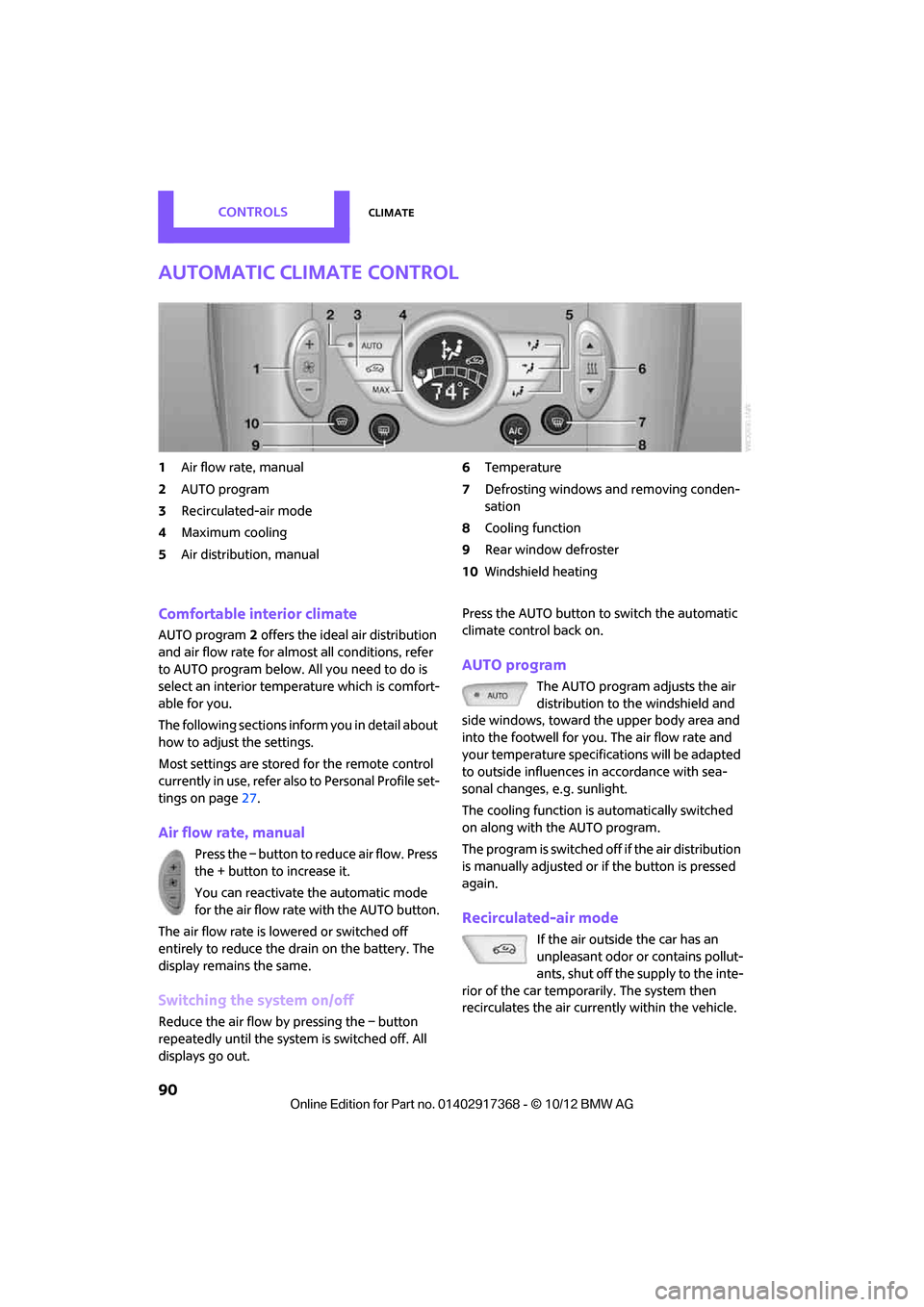
1Air flow rate, manual
2 AUTO program
3 Recirculated-air mode
4 Maximum cooling
5 Air distribution, manual 6
Temperature
7 Defrosting windows and removing conden-
sation
8 Cooling function
9 Rear window defroster
10 Windshield heating
Comfortable interior climate
AUTO program 2 offers the ideal air distribution
and air flow rate for almo st all conditions, refer
to AUTO program below. All you need to do is
select an interior temperature which is comfort-
able for you.
The following sections inform you in detail about
how to adjust the settings.
Most settings are stored for the remote control
currently in use, refer also to Personal Profile set-
tings on page 27.
Air flow rate, manual
Press the – button to reduce air flow. Press
the + button to increase it.
You can reactivate the automatic mode
for the air flow rate with the AUTO button.
The air flow rate is lo wered or switched off
entirely to reduce the drain on the battery. The
display remains the same.
Switching the system on/off
Reduce the air flow by pressing the – button
repeatedly until the system is switched off. All
displays go out. Press the AUTO button to switch the automatic
climate control back on.
AUTO program
The AUTO program adjusts the air
distribution to the windshield and
side windows, toward the upper body area and
into the footwell for you. The air flow rate and
your temperature specifications will be adapted
to outside influences in accordance with sea-
sonal changes, e.g. sunlight.
The cooling function is automatically switched
on along with the AUTO program.
The program is switched off if the air distribution
is manually adjusted or if the button is pressed
again.
Recirculated-air mode
If the air outside the car has an
unpleasant odor or contains pollut-
ants, shut off the supply to the inte-
rior of the car temporarily. The system then
recirculates the air currently within the vehicle.
00320051004F004C00510048000300280047004C0057004C005200510003
Page 92 of 275

ClimateCONTROLS
91
If condensation starts to form on the inside win-
dow surfaces, press the AUTO button or switch
off the recirculated-air mode and, if necessary,
increase the air flow ra te. Ensure that air can
flow onto the windshield.
The recirculated-air mode is automatically deac-
tivated at low outside temperatures.
The recirculated-air mode should not be
used over an extended period of time;
otherwise, the air quali ty in the passenger com-
partment will deteriorate continuously. <
Maximum cooling
The automatic climate control
switches to the lowest tempera-
ture, high airflow and the recircu-
lated-air mode.
For maximum cooling, open the air vents for the
upper body area.
The air is cooled as quickly as possible:
> For an outside temperature of more than
327 /06
> While the motor is running.
Air distribution, manual
The flow of air is directed to the
windows, to the upper body area or
to the footwell as selected.
You can switch the automatic air
distribution back on by pressing the AUTO but-
ton.
Temperature
Set the desired temperature individually.
The automatic climate control achieves
this temperature as quickly as possible
regardless of the season, using maximum
cooling or heating power if necessary, and then
maintains it.
If you switch between different tempera-
ture settings in quic k succession, the auto-
matic climate control do es not have enough
time to achieve the set temperature. <
Rear window defroster
The defroster is switched off auto-
matically after a certain time.
Depending on your vehicle's equip-
ment, the upper wires serve as an
antenna and are not part of the rear window
defroster.
Defrosting windows and removing
condensation
Quickly removes ice and condensa-
tion from the windshield and front
side windows.
For this purpose, also switch on the
cooling function.
The windshield heating
is switched on automat-
ically.
Windshield heating
The windshield heating is switched
off automatically after a certain
time.
Cooling function
When the cooling function is on,
the air is cooled, dried, then
reheated according to the temper-
ature setting. The passenger com-
partment can only be cooled while
the engine is running.
The cooling function helps prevent condensa-
tion on the windows or removes it quickly.
Depending on the weather, the windshield may
fog over briefly when the engine is started. The
recirculated-air mode may be switched on auto-
matically.
When the AUTO button is pressed, the cooling
function switches on automatically.
Microfilter/activated-charcoal filter
The microfilter captures dust and pollen. The
activated-charcoal filter provides additional pro-
tection by filtering gase ous pollutants from the
00320051004F004C00510048000300280047004C0057004C005200510003
Page 93 of 275
CONTROLSClimate
92
outside air. Your MINI dealer replaces this com-
bined filter as a standard part of your scheduled
maintenance.
You can call up further in formation in the service
requirements display, page 64.
Ventilation
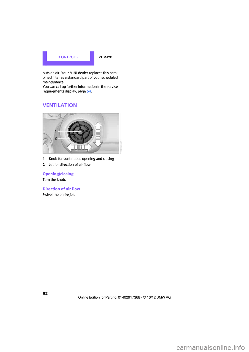
1 Knob for continuous opening and closing
2 Jet for direction of air flow
Opening/closing
Turn the knob.
Direction of air flow
Swivel the entire jet.
00320051004F004C00510048000300280047004C0057004C005200510003
Page 94 of 275
Practical interior accessoriesCONTROLS
93
Practical interior accessories
Vehicle equipment
In this chapter, all production, country, and
optional equipment that is offered in the model
range is described. Equipment is also described
that is not available because of, for example,
selected options or count ry version. This also
applies to safety related functions and systems.
Integrated universal
remote control
The concept
By using the Integrated universal remote con-
trol, up to 3 functions of remote controlled
devices, e.g., garage door openers or lighting
systems, can be operated . As a result, the uni-
versal remote control can replace up to 3 differ-
ent remote controls. To operate, the buttons on
the rearview mirror must be programmed with
the desired functions. For programming, the
remote control for each device is needed.
To prevent possible damage or injury,
before programming or using the inte-
grated universal remote control, always inspect
the immediate area to make certain that no
people, animals or objects are within the travel
range of the device.
Comply also with the safe ty instructions supplied
with the original hand-held transmitter. <
Before selling the vehicle, delete the stored
functions as a safety precaution, page.
Checking compatibility
Depending on your vehicle's equip-
ment, the glove compartment can be
ventilated and, if the cooling function is
switched on, can also be cooled.
For additional information, please contact your
MINI dealer or call: 1-800-355-3515. A list of compatible remo
te controls is available
on the Internet at www.homelink.com.
HomeLink is a registered trademark of Johnson
Controls, Inc.
Operating elements on the rearview
mirror
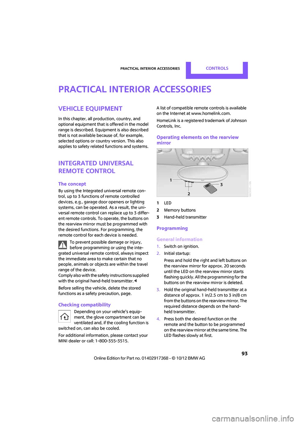
1 LED
2 Memory buttons
3 Hand-held transmitter
Programming
General information
1.Switch on ignition.
2. Initial startup:
Press and hold the righ t and left buttons on
the rearview mirror for approx. 20 seconds
until the LED on the rearview mirror starts
flashing quickly. All the programming for the
buttons on the rearview mirror is deleted.
3. Hold the original hand-held transmitter at a
distance of approx. 1 in/2.5 cm to 3 in/8 cm
from the buttons on the rearview mirror. The
required distance depends on the hand-
held transmitter.
4. Press both the desire d function on the
remote and the button to be programmed
on the rearview mirror at the same time. The
LED flashes slowly at first.
00320051004F004C00510048000300280047004C0057004C005200510003
Page 95 of 275
CONTROLSPractical interior accessories
94
5.As soon as the LED flashes rapidly, release
both buttons. The quick flashing indicates
that the button on the rearview mirror has
been programmed.
If the LED does not flash rapidly after
approx. 60 seconds, alter the distance
between the rearview mirror and hand-held
transmitter and repeat this step. Several
attempts at different distances may be nec-
essary. Wait at least 15 seconds before each
attempt.
Canada: if the programming was interrupted
by the hand-held transm itter, press and hold
the memory button and press the button on
the hand-held transmit ter for 2 seconds and
release several times.
6. To program other functions on other but-
tons, repeat steps 3 to 5.
You can operate the system with the engine
running or with the ignition switched on.
Special features of hopping-code
transmitter systems
If the device cannot be operated after being
programmed repeatedly, then check if the
device to be operated is equipped with a hop-
ping-code system. In a ddition, check in the
operating instructions for the device or press the
programmed button on the rearview mirror for a
longer period of time. If the LED on the rearview
mirror first flashes quickl y and then is on for
2 seconds, then the device is equipped with a
hopping-code system. The flashing and the LED
being on repeats itself for approx. 20 seconds.
In addition, for devices with hopping-code sys-
tems, the integrated universal remote control
and the device must be synchronized.
Information about synchr onizing can be found
in the operating in structions for the device to be
set.
Programming will be easier with the aid of a sec-
ond person. Synchronizing:
1.
Park your vehicle within the range of the
remote-controlled device.
Do not exceed the 164 ft/50 m range of the
remote-controlled device.
2. Program the particular button on the rear-
view mirrors as described.
3. Find and press the button for synchronizing
the device to be set. There remain approx.
30 seconds for the next step.
4. Press and hold the programmed button on
the rearview mirror for approx. 3seconds
and then release. Repeat this step, possibly
up to three times, to complete the synchro-
nization. After the sy nchronization is com-
pleted, the programmed function is imple-
mented.
To reprogram individual buttons
1. Switch on ignition.
2. Press and hold the button to be pro-
grammed on the rearview mirror.
3. As soon as the LED on the rearview mirror
starts flashing slowly, hold the hand-held
transmitter of the device to be operated
approx. 1in/2.5cm to 3in/8cm from the
buttons on the rearview mirror. The required
distance depends on the hand-held trans-
mitter.
4. Press and also hold the button with the
desired function on the hand-held transmit-
ter.
5. As soon as the LED on the rearview mirror
starts blinking faster, release both buttons.
The quick flashing indicates that the button
on the rearview mirror has been pro-
grammed. The device can now be operated
using the button on the rearview mirror.
Canada: if the LED is not flashing rapidly
after 60 seconds, change the distance and
repeat the step or, if the programming was
interrupted by the hand-held transmitter,
press and hold the memory button and
00320051004F004C00510048000300280047004C0057004C005200510003
Page 96 of 275
Practical interior accessoriesCONTROLS
95
press the button on the hand-held transmit-
ter for 2 seconds and release several times.
Operation
Before using the integrated universal
remote control, always inspect the imme-
diate area to make certain that no people, ani-
mals or objects are within the travel range of the
device.
Comply also with the safe ty instructions supplied
with the original hand-held transmitter. <
The device, for example a garage door, can be
operated while the engine is running or when
the ignition is on by using the button on the
rearview mirror. In addi tion, while within the
reception range of the device, press the button
until the function is deleted. The LED on the
rearview mirror is constant ly on while the signal
is being transmitted.
Deleting stored functions
Press and hold the right and left buttons on the
rearview mirror for approx. 20 seconds until the
LED on the rearview mirror starts flashing
quickly. All stored functions are deleted. The
functions can not be deleted individually.
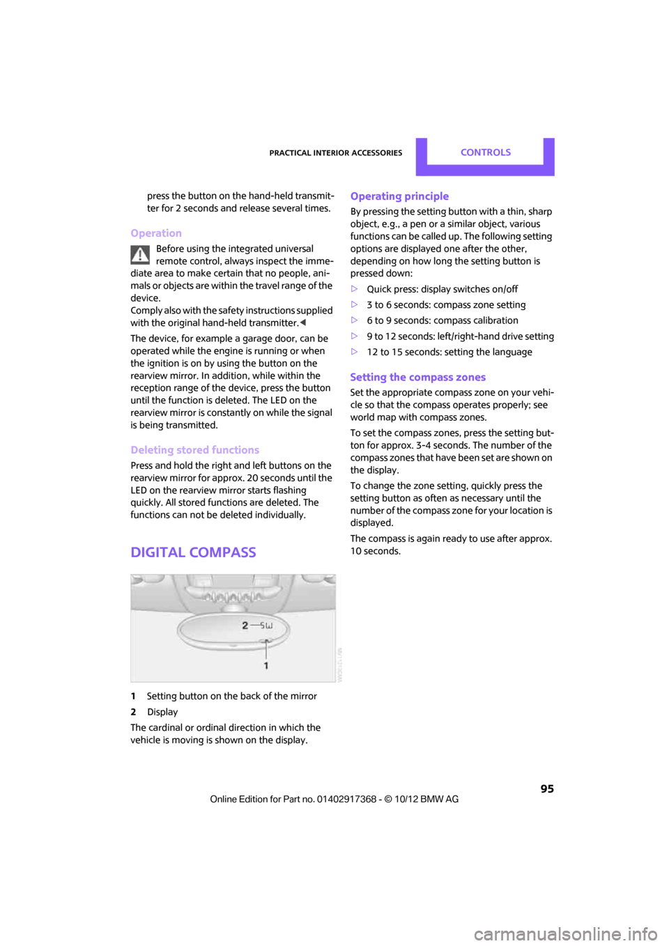
Digital compass
1 Setting button on the back of the mirror
2 Display
The cardinal or ordinal direction in which the
vehicle is moving is shown on the display.
Operating principle
By pressing the setting button with a thin, sharp
object, e.g., a pen or a similar object, various
functions can be called up. The following setting
options are displayed one after the other,
depending on how long the setting button is
pressed down:
> Quick press: display switches on/off
> 3 to 6 seconds: compass zone setting
> 6 to 9 seconds: compass calibration
> 9 to 12 seconds: left/right-hand drive setting
> 12 to 15 seconds: setting the language
Setting the compass zones
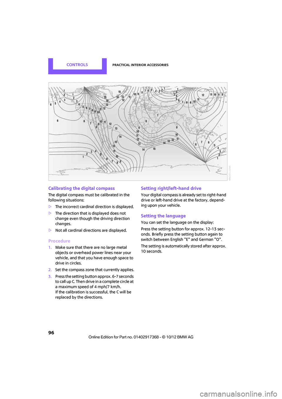
Set the appropriate compass zone on your vehi-
cle so that the compass operates properly; see
world map with compass zones.
To set the compass zones, press the setting but-
ton for approx. 3-4 seconds. The number of the
compass zones that have been set are shown on
the display.
To change the zone se tting, quickly press the
setting button as often as necessary until the
number of the compass zone for your location is
displayed.
The compass is again ready to use after approx.
10 seconds.
00320051004F004C00510048000300280047004C0057004C005200510003
Page 97 of 275
CONTROLSPractical interior accessories
96
Calibrating the digital compass
The digital compass must be calibrated in the
following situations:
>The incorrect cardinal direction is displayed.
> The direction that is displayed does not
change even though the driving direction
changes.
> Not all cardinal directions are displayed.
Procedure
1.Make sure that there are no large metal
objects or overhead power lines near your
vehicle, and that you have enough space to
drive in circles.
2. Set the compass zone th at currently applies.
3. Press the setting button approx. 6-7 seconds
to call up C. Then drive in a complete circle at
a maximum speed of 4 mph/7 km/h.
If the calibration is successful, the C will be
replaced by the directions.
Setting right/left-hand drive
Your digital compass is already set to right-hand
drive or left-hand drive at the factory, depend-
ing upon your vehicle.
Setting the language
You can set the language on the display:
Press the setting button for approx. 12-13 sec-
onds. Briefly press the setting button again to
switch between English "E" and German "O".
The setting is automatically stored after approx.
10 seconds.
00320051004F004C00510048000300280047004C0057004C005200510003
Page 98 of 275
Practical interior accessoriesCONTROLS
97
Glove compartment
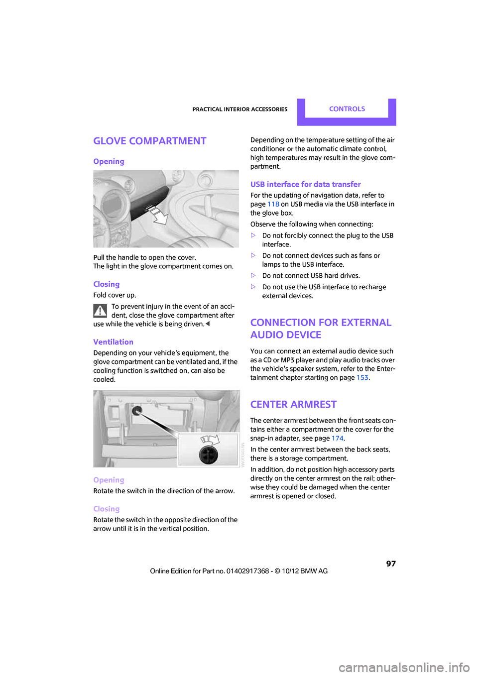
Opening
Pull the handle to open the cover.
The light in the glove compartment comes on.
Closing
Fold cover up.To prevent injury in the event of an acci-
dent, close the glove compartment after
use while the vehicle is being driven. <
Ventilation
Depending on your vehicle's equipment, the
glove compartment can be ventilated and, if the
cooling function is switched on, can also be
cooled.
Opening
Rotate the switch in the direction of the arrow.
Closing
Rotate the switch in the opposite direction of the
arrow until it is in the vertical position. Depending on the temperature setting of the air
conditioner or the automatic climate control,
high temperatures may result in the glove com-
partment.
USB interface for data transfer
For the updating of navi
gation data, refer to
page 118 on USB media via the USB interface in
the glove box.
Observe the following when connecting:
> Do not forcibly connect the plug to the USB
interface.
> Do not connect devices such as fans or
lamps to the USB interface.
> Do not connect USB hard drives.
> Do not use the USB interface to recharge
external devices.
Connection for external
audio device
You can connect an external audio device such
as a CD or MP3 player an d play audio tracks over
the vehicle's speaker system, refer to the Enter-
tainment chapter starting on page 153.
Center armrest
The center armrest between the front seats con-
tains either a compartment or the cover for the
snap-in adapter, see page 174.
In the center armrest between the back seats,
there is a storage compartment.
In addition, do not position high accessory parts
directly on the center armrest on the rail; other-
wise they could be damaged when the center
armrest is opened or closed.
00320051004F004C00510048000300280047004C0057004C005200510003
Page 99 of 275
CONTROLSPractical interior accessories
98
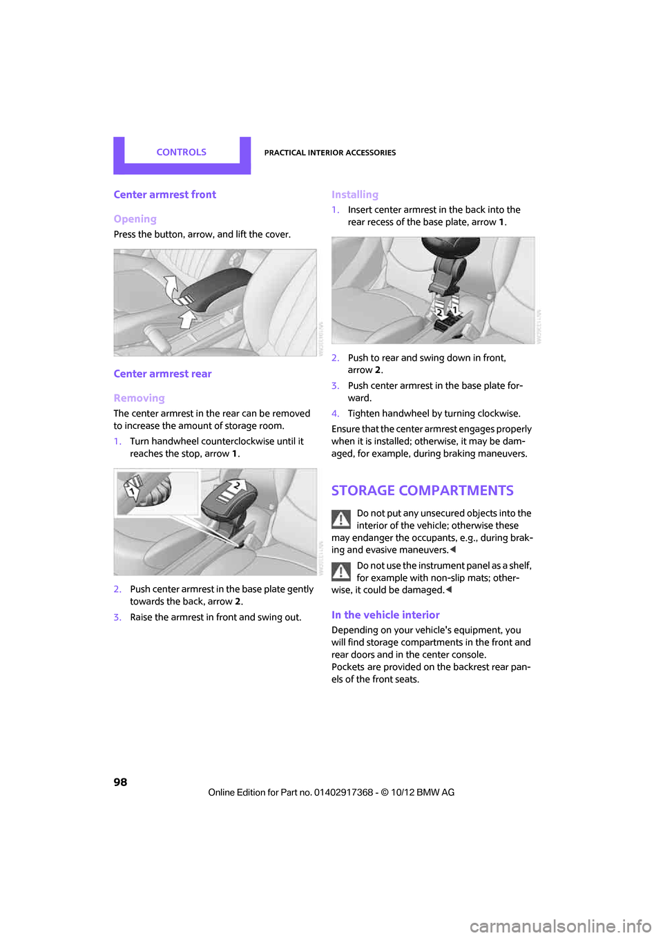
Center armrest front
Opening
Press the button, arrow, and lift the cover.
Center armrest rear
Removing
The center armrest in the rear can be removed
to increase the amount of storage room.
1.Turn handwheel counterclockwise until it
reaches the stop, arrow 1.
2. Push center armrest in the base plate gently
towards the back, arrow 2.
3. Raise the armrest in front and swing out.
Installing
1.Insert center armrest in the back into the
rear recess of the base plate, arrow 1.
2. Push to rear and swing down in front,
arrow 2.
3. Push center armrest in the base plate for-
ward.
4. Tighten handwheel by turning clockwise.
Ensure that the center armrest engages properly
when it is installed; ot herwise, it may be dam-
aged, for example, during braking maneuvers.
Storage compartments
Do not put any unsecured objects into the
interior of the vehicle; otherwise these
may endanger the occupant s, e.g., during brak-
ing and evasive maneuvers. <
Do not use the instrument panel as a shelf,
for example with non-slip mats; other-
wise, it could be damaged. <
In the vehicle interior
Depending on your vehicle's equipment, you
will find storage compartments in the front and
rear doors and in the center console.
Pockets
are provided on the backrest rear pan-
els of the front seats.
00320051004F004C00510048000300280047004C0057004C005200510003
Page 100 of 275
Practical interior accessoriesCONTROLS
99
Center Rail
Various accessory parts can be attached to the
Center Rail and installe d in different positions.
Do not use accessory parts near the hand
brake; otherwise these could be damaged
when the hand brake lever is operated. <
Smartphone holder
The upper part of the smartphone holder can be
rotated by 360°.
When installing in the front of the rail, make sure
that there is sufficient space, e.g., away from the
seat; otherwise, damage may be caused when
rotating.
1. Pull the lever 1 up to unlock the mounts.
2. First install the smartp hone on the Center
Rail with the mounts 2.
3. To secure, push lever 1 down. Ensure that
the lever can lock it properly.
When connecting a smartphone to the USB
audio interface, see page 154, guide the con-
nection cable under the smartphone holder.
Base plate
On the base plate, vari ous accessories can be
attached, such as cup holders, holders for sun-
glasses and cell phone holders.
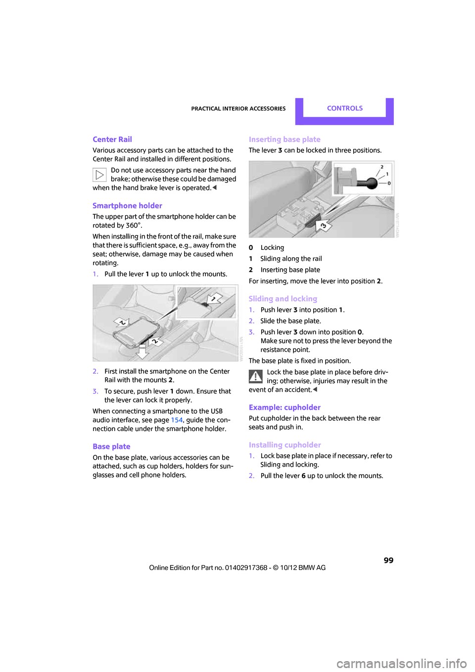
Inserting base plate
The lever 3 can be locked in three positions.
0 Locking
1 Sliding along the rail
2 Inserting base plate
For inserting, move th e lever into position2.
Sliding and locking
1. Push lever 3 into position 1.
2. Slide the base plate.
3. Push lever 3 down into position 0.
Make sure not to press the lever beyond the
resistance point.
The base plate is fixed in position.
Lock the base plate in place before driv-
ing; otherwise, injuries may result in the
event of an accident. <
Example: cupholder
Put cupholder in the back between the rear
seats and push in.
Installing cupholder
1.Lock base plate in plac e if necessary, refer to
Sliding and locking.
2. Pull the lever 6 up to unlock the mounts.
00320051004F004C00510048000300280047004C0057004C005200510003