radio MINI Paceman 2014 (Mini Connected) Owner's Guide
[x] Cancel search | Manufacturer: MINI, Model Year: 2014, Model line: Paceman, Model: MINI Paceman 2014Pages: 282, PDF Size: 6.76 MB
Page 181 of 282
▷Bluetooth presettings may need to be
made on the mobile phone, e.g., for a con‐
nection without confirmation or visibility,
refer to the mobile phone operating in‐
structions.▷Deactivate Bluetooth audio if necessary.▷A number with at least four and a maxi‐
mum of 16 digits was defined as the Blue‐
tooth passkey. It is only required once for
pairing.▷Compare the control number on the Control
Display with the control number on the mo‐
bile phone display. Confirm the control
number on the mobile phone and in the
vehicle.▷The radio ready state is switched on.
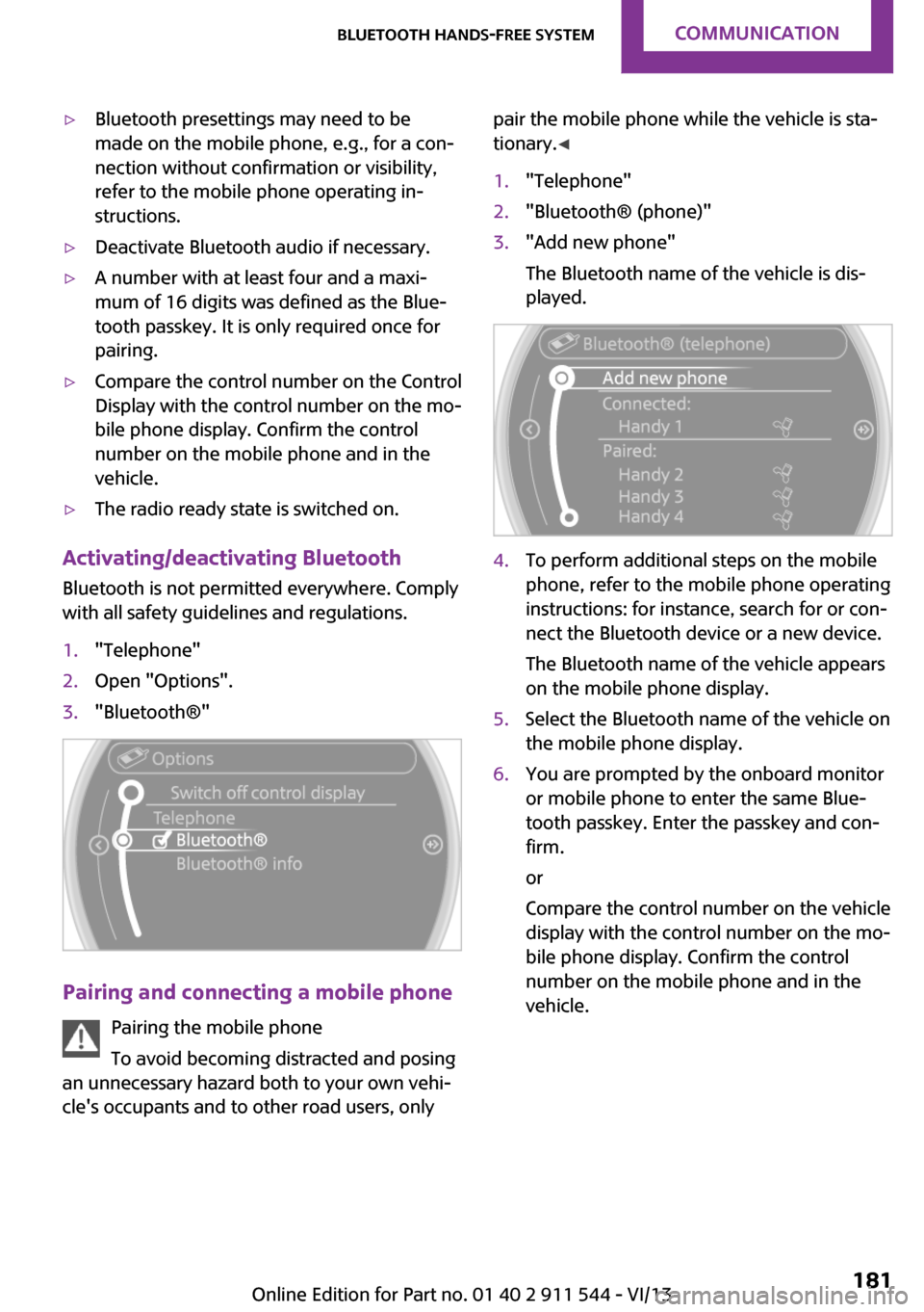
Activating/deactivating Bluetooth
Bluetooth is not permitted everywhere. Comply
with all safety guidelines and regulations.
1."Telephone"2.Open "Options".3."Bluetooth®"
Pairing and connecting a mobile phone
Pairing the mobile phone
To avoid becoming distracted and posing
an unnecessary hazard both to your own vehi‐
cle's occupants and to other road users, only
pair the mobile phone while the vehicle is sta‐
tionary. ◀1."Telephone"2."Bluetooth® (phone)"3."Add new phone"
The Bluetooth name of the vehicle is dis‐
played.4.To perform additional steps on the mobile
phone, refer to the mobile phone operating
instructions: for instance, search for or con‐
nect the Bluetooth device or a new device.
The Bluetooth name of the vehicle appears
on the mobile phone display.5.Select the Bluetooth name of the vehicle on
the mobile phone display.6.You are prompted by the onboard monitor
or mobile phone to enter the same Blue‐
tooth passkey. Enter the passkey and con‐
firm.
or
Compare the control number on the vehicle
display with the control number on the mo‐
bile phone display. Confirm the control
number on the mobile phone and in the
vehicle.Seite 181Bluetooth hands-free systemCommunication181
Online Edition for Part no. 01 40 2 911 544 - VI/13
Page 191 of 282
NotesAt high temperatures, the charging function of
the mobile phone may be limited and functions
may not be executed.
When using the mobile phone via the vehicle,
note the operating instructions of the mobile
phone.
Pairing/unpairing the
mobile phone
General information
The following functions are available:▷Use of a mobile phone as a telephone.▷Use of a mobile phone as an additional te‐
lephone.▷Use of a mobile phone as an audio source.▷Use of an audio device as an audio source,
refer to page 173.
Requirements
▷The mobile phone is suitable, refer to
page 190.▷The mobile phone is ready for operation.▷Bluetooth is activated in the vehicle and on
the mobile phone.▷Bluetooth presettings may need to be
made on the mobile phone, e.g., for a con‐
nection without confirmation or visibility,
refer to the mobile phone operating in‐
structions.▷Deactivate Bluetooth audio if necessary.▷Compare the control number on the Control
Display with the control number on the mo‐
bile phone display. Confirm the control
number on the mobile phone and in the
vehicle.▷A number with at least four and a maxi‐
mum of 16 digits was defined as the Blue‐tooth passkey. It is only required once for
pairing.▷The radio ready state is switched on.
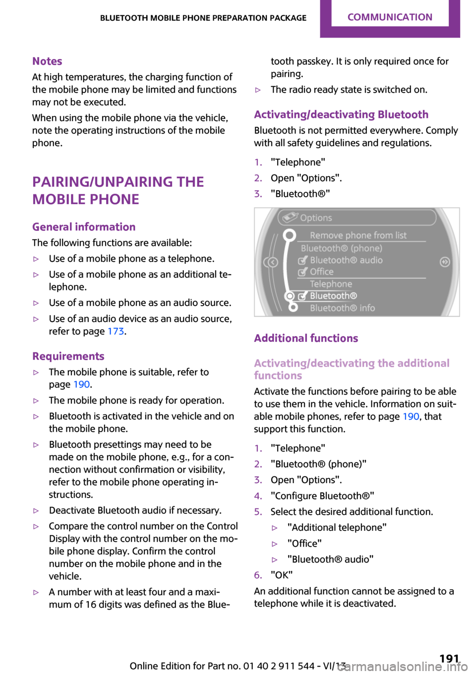
Activating/deactivating Bluetooth
Bluetooth is not permitted everywhere. Comply
with all safety guidelines and regulations.
1."Telephone"2.Open "Options".3."Bluetooth®"
Additional functions
Activating/deactivating the additional functions
Activate the functions before pairing to be able
to use them in the vehicle. Information on suit‐
able mobile phones, refer to page 190, that
support this function.
1."Telephone"2."Bluetooth® (phone)"3.Open "Options".4."Configure Bluetooth®"5.Select the desired additional function.▷"Additional telephone"▷"Office"▷"Bluetooth® audio"6."OK"
An additional function cannot be assigned to a
telephone while it is deactivated.
Seite 191Bluetooth mobile phone preparation packageCommunication191
Online Edition for Part no. 01 40 2 911 544 - VI/13
Page 200 of 282
Snap-in adapter
General information More information on compatible snap-in
adapters that support the functions of the mo‐
bile phone is available at the service center.
Notes At high temperatures, the charging function of
the mobile phone may be limited and functions
may not be executed.
When using the mobile phone via the vehicle,
note the operating instructions of the mobile
phone.
Installation position In the center armrest.
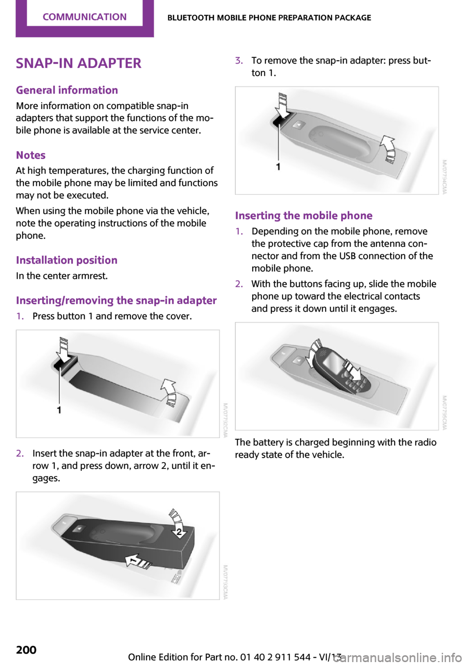
Inserting/removing the snap-in adapter1.Press button 1 and remove the cover.2.Insert the snap-in adapter at the front, ar‐
row 1, and press down, arrow 2, until it en‐
gages.3.To remove the snap-in adapter: press but‐
ton 1.
Inserting the mobile phone
1.Depending on the mobile phone, remove
the protective cap from the antenna con‐
nector and from the USB connection of the
mobile phone.2.With the buttons facing up, slide the mobile
phone up toward the electrical contacts
and press it down until it engages.
The battery is charged beginning with the radio
ready state of the vehicle.
Seite 200CommunicationBluetooth mobile phone preparation package200
Online Edition for Part no. 01 40 2 911 544 - VI/13
Page 211 of 282

Control Display and can be operated using the
MINI joystick.
The volume can be set using the following con‐
trols:▷
Buttons on the steering
wheel or
▷Volume button on the radio, refer to
page 1581.Connect the mobile phone via the snap-in
adapter or via the USB audio interface.2. Press the button. The main menu is
opened.3."MINI Connected"4.Select the desired software application.
Notes
▷The scope of MINI Connected that can be
displayed on the Control Display depends
on the range of software applications in‐
stalled on the mobile phone.▷The data transmission of the software ap‐
plications from the mobile phone to the ve‐
hicle can last some time. Some software
applications depend on the speed of the
available Internet connection of the mobile
phone.▷Some mobile phones cannot simultane‐
ously use MINI Connected and the Blue‐
tooth hands-free system.If necessary, restart the software applica‐
tion on the mobile phone after a phone
conversation.▷Audio and video playback from the snap-in
adapter is only possible if no cable is con‐
nected to the AV-IN port.
PlugIn
The concept
Selected functions of a compatible Apple de‐
vice can be displayed on the Control Display via
a video connection. They are operated using
the MINI joystick and the button on the
MINI joystick.
Functional requirement
▷Suitable iPhone or iPod: as of iPhone 3GS or
iPod with software version iOS 4.1 and
higher.▷The MINI Connected app is not required.
Information on compatible adapters and inter‐
faces can be obtained from the service center.
Activating
1.Connect the Apple device.
Operation takes place via the MINI joystick
with its buttons.2."MINI Connected"3."PlugIn"4.Select the connection type: "Activate via
AUX connection" or"Activate via Snap-In
adapter"5."Activate PlugIn"6.Use the MINI joystick to navigate among
the displayed functions and select, for ex‐
ample, a desired category or track.
Controls
The PlugIn is activated to display the graphic
output of the connected device on the Control
Seite 211MINI ConnectedCommunication211
Online Edition for Part no. 01 40 2 911 544 - VI/13
Page 246 of 282

Vehicle batteryMaintenance
The battery is maintenance-free, i.e., the elec‐
trolyte will last for the life of the battery in tem‐
perate climate conditions.
The service center will be happy to answer any
questions on the battery.
Battery replacement Use approved vehicle batteries
Only use vehicle batteries that have been
approved for your vehicle by the manufacturer;
otherwise, the vehicle could be damaged and
systems or functions may not be fully availa‐
ble. ◀
Have the vehicle battery registered by the serv‐
ice center after it is replaced to ensure that all
comfort functions are available without restric‐
tions and that any associated Check Control
messages are no longer displayed.
Charging the battery
Note Do not connect the charger to the socket
Do not connect the battery charger to the
socket installed in the vehicle at the factory as
this could damage the battery. ◀
Only charge the battery in the vehicle when the engine is switched off. Connections, refer to
page 248.
General information Ensure that the battery is sufficiently charged to
achieve the full battery life.
It may be necessary to charge the battery in
the following cases:▷When the vehicle is frequently used to
travel short distances.▷When the vehicle has not been driven for
more than one month.Power failure
After a temporary power failure, some equip‐
ment will be restricted in its use and will need
to be reinitialized. In addition, certain individual
settings will be lost and must be updated:▷Time and date: the values must be up‐
dated, refer to page 72.▷Radio: the stations need to be stored again,
refer to page 159.▷Onboard monitor: full functionality will be
restored after some time.▷Glass sunroof, electrical: it may only be pos‐
sible to tilt the roof. The system needs to be
initialized. Contact the service center.
Indicator/warning lamps
Lights up red: the vehicle battery is no
longer being charged. Alternator mal‐
function.
Switch off all unnecessary electrical consumers.
Have the battery checked immediately.
Lights up yellow: the battery charge
level is very low, the battery is old, or it
is not securely connected.
Charge the battery by taking a long drive or us‐
ing an external charger. If the indicators appear
again, have the battery checked as soon as
possible.
Disposing of old batteries Have used batteries disposed of by the
service center after they are replaced or
take them to a recycling center.
Maintain the battery in an upright position for
transport and storage. Secure the battery so
that it does not tip over during transport.
Seite 246MobilityReplacing components246
Online Edition for Part no. 01 40 2 911 544 - VI/13
Page 257 of 282

Chrome surfacesCarefully clean components such as the radia‐
tor grille or door handles with an ample supply
of water, possibly with shampoo added, partic‐
ularly when they have been exposed to road
salt. For additional treatment, use a chrome
polish.
Light-alloy wheels
When cleaning the wheels on the vehicle, only
use a neutral wheel rim cleaner with a pH value
of 5 to 9.
Do not use abrasive cleaners or a steam jet hot‐
ter than 140 ℉/60 ℃; otherwise, damage may
result. Adhere to the manufacturer instructions.
Aggressive, acidic, or alkaline cleaners may de‐
stroy the protective coating of neighboring
components such as the brake disc.
Exterior sensors The sensors on the outside of the vehicle, such
as for Park Distance Control, must be kept clean
and free of ice to ensure that they remain fully
functional.
Decorative trim Clean decorative trims and fine wood compo‐
nents with a moist cloth only. Then dry with a
soft cloth.
Safety belts Dirty belt straps impede the reeling action and
thus have a negative impact on safety.
No chemical cleaning
Do not clean chemically; this can destroy
the webbing. ◀
Carpets/floor mats No objects in the area around the pedals
Keep floor mats, carpets, and any other
objects out of the area of motion of the pedals;
otherwise, the function of the pedals could be
impeded while drivingDo not place additional floor mats over existing
mats or other objects.
Only use floor mats that have been approved
for the vehicle and can be properly fixed in
place.
Ensure that the floor mats are securely fastened
again when they are returned after being re‐
moved, such as for cleaning. ◀
Floor mats can be removed for cleaning.
If they are very dirty, clean with a microfiber
cloth and water or an interior cleaner. To pre‐
vent matting of the carpet, rub back and forth
in the direction of travel only.
Displays
To clean the displays, such as the radio or dis‐
play elements, use an antistatic microfiber
cloth.
Cleaning displays
Do not use chemical or household cleans‐
ers.
Keep all fluids and moisture away from the
unit.
Otherwise, they could affect or damage surfa‐
ces or electrical components.
Avoid pressing too hard when cleaning and do
not use abrasive materials; otherwise, damage
can result. ◀
CD/DVD drives No cleaning CD
Do not use cleaning CDs; otherwise, parts
of the drive may become damaged. ◀
Long-term vehicle storage
Your service center can advise you on what to
consider when storing the vehicle for longer
than three months.Seite 257CareMobility257
Online Edition for Part no. 01 40 2 911 544 - VI/13
Page 267 of 282
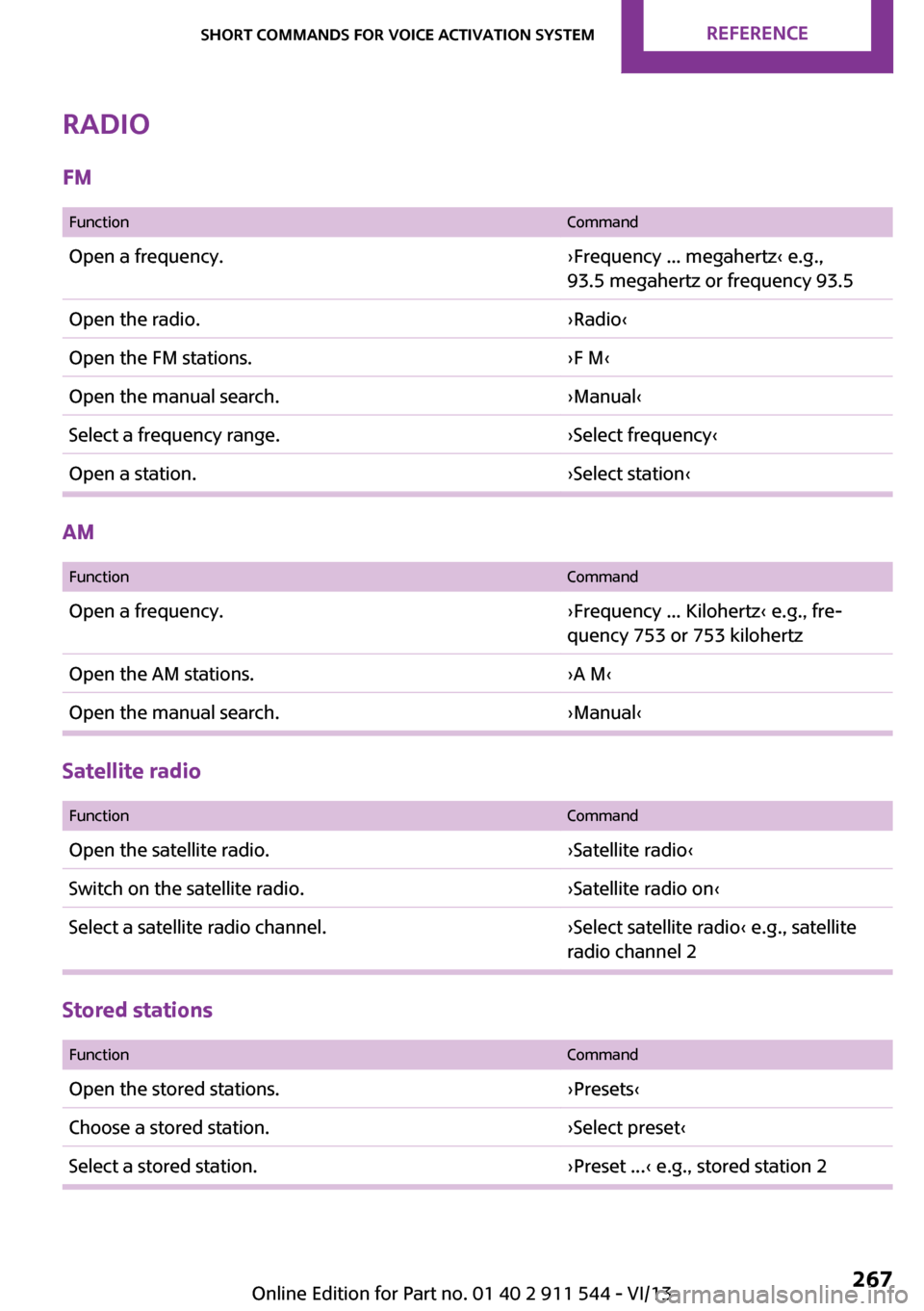
Radio
FM
FunctionCommandOpen a frequency.›Frequency ... megahertz‹ e.g.,
93.5 megahertz or frequency 93.5Open the radio.›Radio‹Open the FM stations.›F M‹Open the manual search.›Manual‹Select a frequency range.›Select frequency‹Open a station.›Select station‹
AM
FunctionCommandOpen a frequency.›Frequency ... Kilohertz‹ e.g., fre‐
quency 753 or 753 kilohertzOpen the AM stations.›A M‹Open the manual search.›Manual‹
Satellite radio
FunctionCommandOpen the satellite radio.›Satellite radio‹Switch on the satellite radio.›Satellite radio on‹Select a satellite radio channel.›Select satellite radio‹ e.g., satellite
radio channel 2
Stored stations
FunctionCommandOpen the stored stations.›Presets‹Choose a stored station.›Select preset‹Select a stored station.›Preset ...‹ e.g., stored station 2Seite 267Short commands for voice activation systemReference267
Online Edition for Part no. 01 40 2 911 544 - VI/13
Page 272 of 282
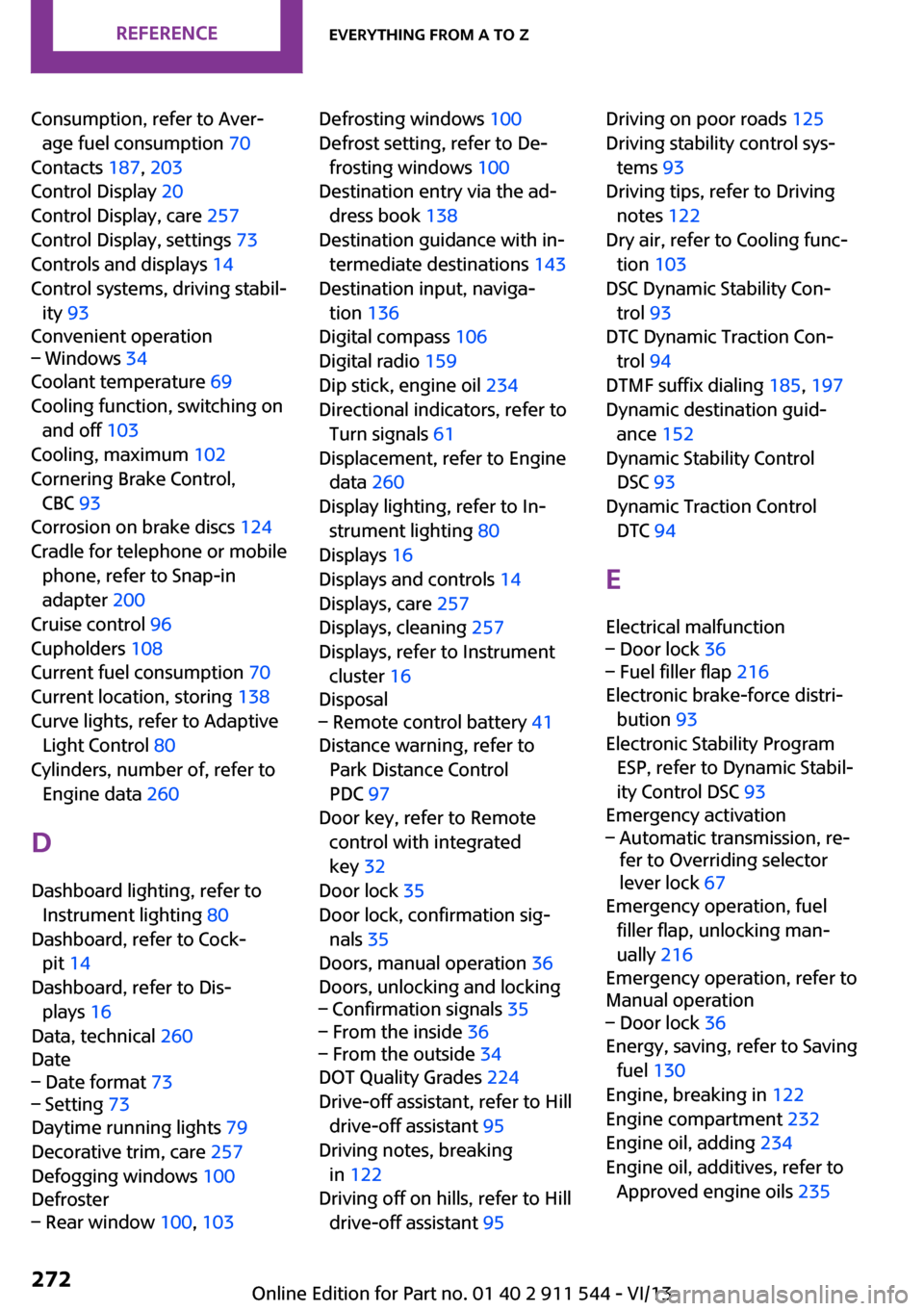
Consumption, refer to Aver‐age fuel consumption 70
Contacts 187, 203
Control Display 20
Control Display, care 257
Control Display, settings 73
Controls and displays 14
Control systems, driving stabil‐ ity 93
Convenient operation– Windows 34
Coolant temperature 69
Cooling function, switching on and off 103
Cooling, maximum 102
Cornering Brake Control, CBC 93
Corrosion on brake discs 124
Cradle for telephone or mobile phone, refer to Snap-in
adapter 200
Cruise control 96
Cupholders 108
Current fuel consumption 70
Current location, storing 138
Curve lights, refer to Adaptive Light Control 80
Cylinders, number of, refer to Engine data 260
D
Dashboard lighting, refer to Instrument lighting 80
Dashboard, refer to Cock‐ pit 14
Dashboard, refer to Dis‐ plays 16
Data, technical 260
Date
– Date format 73– Setting 73
Daytime running lights 79
Decorative trim, care 257
Defogging windows 100
Defroster
– Rear window 100, 103Defrosting windows 100
Defrost setting, refer to De‐ frosting windows 100
Destination entry via the ad‐ dress book 138
Destination guidance with in‐ termediate destinations 143
Destination input, naviga‐ tion 136
Digital compass 106
Digital radio 159
Dip stick, engine oil 234
Directional indicators, refer to Turn signals 61
Displacement, refer to Engine data 260
Display lighting, refer to In‐ strument lighting 80
Displays 16
Displays and controls 14
Displays, care 257
Displays, cleaning 257
Displays, refer to Instrument cluster 16
Disposal– Remote control battery 41
Distance warning, refer to
Park Distance Control
PDC 97
Door key, refer to Remote control with integrated
key 32
Door lock 35
Door lock, confirmation sig‐ nals 35
Doors, manual operation 36
Doors, unlocking and locking
– Confirmation signals 35– From the inside 36– From the outside 34
DOT Quality Grades 224
Drive-off assistant, refer to Hill drive-off assistant 95
Driving notes, breaking in 122
Driving off on hills, refer to Hill drive-off assistant 95
Driving on poor roads 125
Driving stability control sys‐ tems 93
Driving tips, refer to Driving notes 122
Dry air, refer to Cooling func‐ tion 103
DSC Dynamic Stability Con‐ trol 93
DTC Dynamic Traction Con‐ trol 94
DTMF suffix dialing 185, 197
Dynamic destination guid‐ ance 152
Dynamic Stability Control DSC 93
Dynamic Traction Control DTC 94
E Electrical malfunction– Door lock 36– Fuel filler flap 216
Electronic brake-force distri‐
bution 93
Electronic Stability Program ESP, refer to Dynamic Stabil‐
ity Control DSC 93
Emergency activation
– Automatic transmission, re‐
fer to Overriding selector
lever lock 67
Emergency operation, fuel
filler flap, unlocking man‐
ually 216
Emergency operation, refer to
Manual operation
– Door lock 36
Energy, saving, refer to Saving
fuel 130
Engine, breaking in 122
Engine compartment 232
Engine oil, adding 234
Engine oil, additives, refer to Approved engine oils 235
Seite 272ReferenceEverything from A to Z272
Online Edition for Part no. 01 40 2 911 544 - VI/13
Page 274 of 282
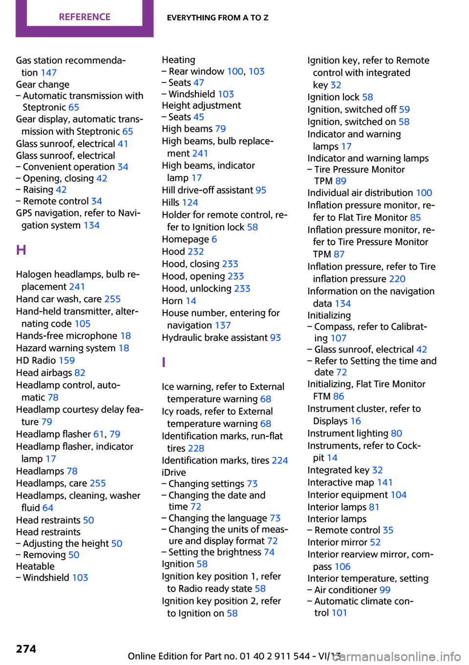
Gas station recommenda‐tion 147
Gear change– Automatic transmission with
Steptronic 65
Gear display, automatic trans‐
mission with Steptronic 65
Glass sunroof, electrical 41
Glass sunroof, electrical
– Convenient operation 34– Opening, closing 42– Raising 42– Remote control 34
GPS navigation, refer to Navi‐
gation system 134
H Halogen headlamps, bulb re‐ placement 241
Hand car wash, care 255
Hand-held transmitter, alter‐ nating code 105
Hands-free microphone 18
Hazard warning system 18
HD Radio 159
Head airbags 82
Headlamp control, auto‐ matic 78
Headlamp courtesy delay fea‐ ture 79
Headlamp flasher 61, 79
Headlamp flasher, indicator lamp 17
Headlamps 78
Headlamps, care 255
Headlamps, cleaning, washer fluid 64
Head restraints 50
Head restraints
– Adjusting the height 50– Removing 50
Heatable
– Windshield 103Heating– Rear window 100, 103– Seats 47– Windshield 103
Height adjustment
– Seats 45
High beams 79
High beams, bulb replace‐ ment 241
High beams, indicator lamp 17
Hill drive-off assistant 95
Hills 124
Holder for remote control, re‐ fer to Ignition lock 58
Homepage 6
Hood 232
Hood, closing 233
Hood, opening 233
Hood, unlocking 233
Horn 14
House number, entering for navigation 137
Hydraulic brake assistant 93
I
Ice warning, refer to External temperature warning 68
Icy roads, refer to External temperature warning 68
Identification marks, run-flat tires 228
Identification marks, tires 224
iDrive
– Changing settings 73– Changing the date and
time 72– Changing the language 73– Changing the units of meas‐
ure and display format 72– Setting the brightness 74
Ignition 58
Ignition key position 1, refer to Radio ready state 58
Ignition key position 2, refer to Ignition on 58
Ignition key, refer to Remote
control with integrated
key 32
Ignition lock 58
Ignition, switched off 59
Ignition, switched on 58
Indicator and warning lamps 17
Indicator and warning lamps– Tire Pressure Monitor
TPM 89
Individual air distribution 100
Inflation pressure monitor, re‐ fer to Flat Tire Monitor 85
Inflation pressure monitor, re‐ fer to Tire Pressure Monitor
TPM 87
Inflation pressure, refer to Tire inflation pressure 220
Information on the navigation data 134
Initializing
– Compass, refer to Calibrat‐
ing 107– Glass sunroof, electrical 42– Refer to Setting the time and
date 72
Initializing, Flat Tire Monitor
FTM 86
Instrument cluster, refer to Displays 16
Instrument lighting 80
Instruments, refer to Cock‐ pit 14
Integrated key 32
Interactive map 141
Interior equipment 104
Interior lamps 81
Interior lamps
– Remote control 35
Interior mirror 52
Interior rearview mirror, com‐ pass 106
Interior temperature, setting
– Air conditioner 99– Automatic climate con‐
trol 101Seite 274ReferenceEverything from A to Z274
Online Edition for Part no. 01 40 2 911 544 - VI/13
Page 276 of 282
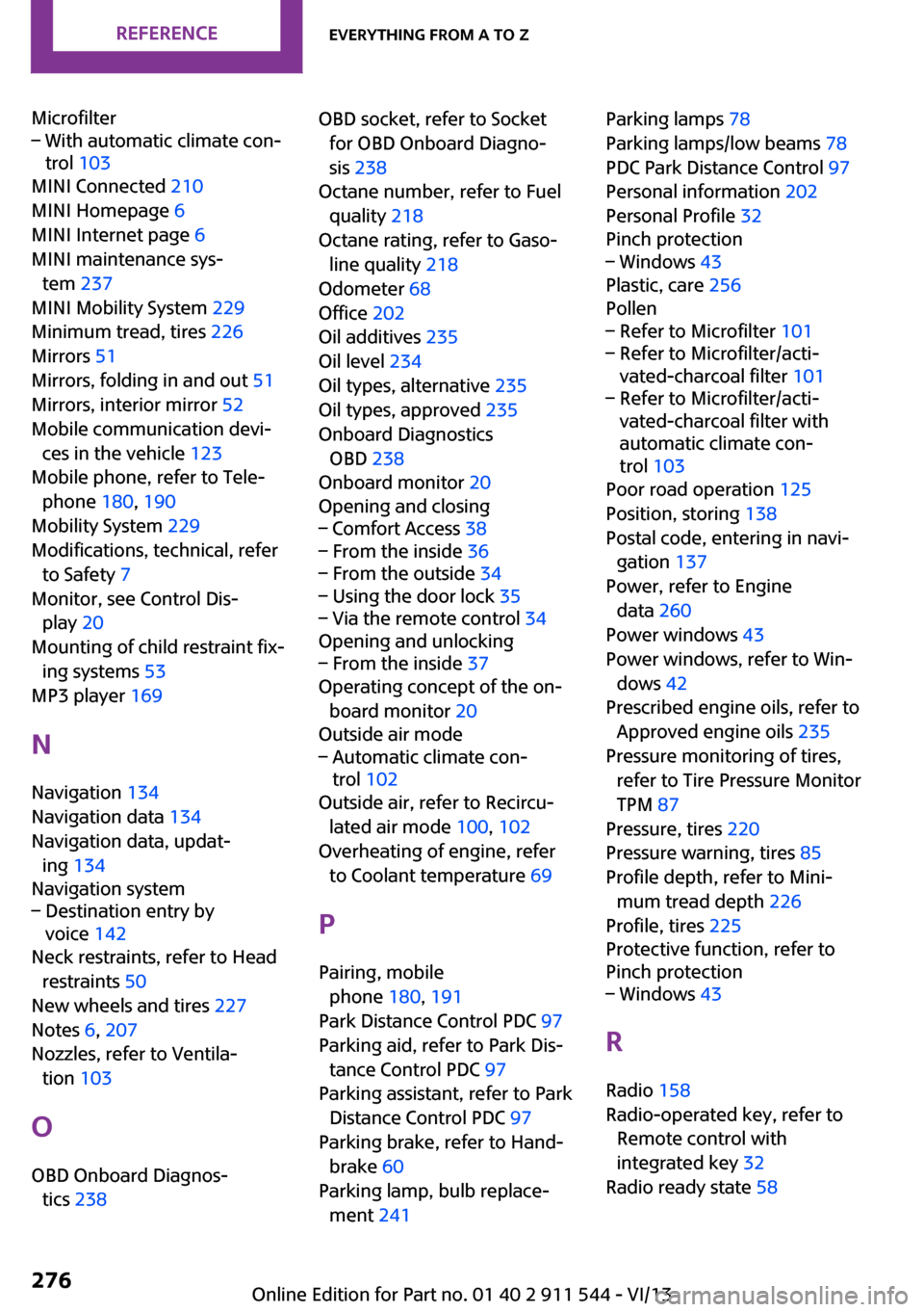
Microfilter– With automatic climate con‐
trol 103
MINI Connected 210
MINI Homepage 6
MINI Internet page 6
MINI maintenance sys‐ tem 237
MINI Mobility System 229
Minimum tread, tires 226
Mirrors 51
Mirrors, folding in and out 51
Mirrors, interior mirror 52
Mobile communication devi‐ ces in the vehicle 123
Mobile phone, refer to Tele‐ phone 180, 190
Mobility System 229
Modifications, technical, refer to Safety 7
Monitor, see Control Dis‐ play 20
Mounting of child restraint fix‐ ing systems 53
MP3 player 169
N
Navigation 134
Navigation data 134
Navigation data, updat‐ ing 134
Navigation system
– Destination entry by
voice 142
Neck restraints, refer to Head
restraints 50
New wheels and tires 227
Notes 6, 207
Nozzles, refer to Ventila‐ tion 103
O
OBD Onboard Diagnos‐ tics 238
OBD socket, refer to Socket
for OBD Onboard Diagno‐
sis 238
Octane number, refer to Fuel quality 218
Octane rating, refer to Gaso‐ line quality 218
Odometer 68
Office 202
Oil additives 235
Oil level 234
Oil types, alternative 235
Oil types, approved 235
Onboard Diagnostics OBD 238
Onboard monitor 20
Opening and closing– Comfort Access 38– From the inside 36– From the outside 34– Using the door lock 35– Via the remote control 34
Opening and unlocking
– From the inside 37
Operating concept of the on‐
board monitor 20
Outside air mode
– Automatic climate con‐
trol 102
Outside air, refer to Recircu‐
lated air mode 100, 102
Overheating of engine, refer to Coolant temperature 69
P Pairing, mobile phone 180, 191
Park Distance Control PDC 97
Parking aid, refer to Park Dis‐ tance Control PDC 97
Parking assistant, refer to Park Distance Control PDC 97
Parking brake, refer to Hand‐ brake 60
Parking lamp, bulb replace‐ ment 241
Parking lamps 78
Parking lamps/low beams 78
PDC Park Distance Control 97
Personal information 202
Personal Profile 32
Pinch protection– Windows 43
Plastic, care 256
Pollen
– Refer to Microfilter 101– Refer to Microfilter/acti‐
vated-charcoal filter 101– Refer to Microfilter/acti‐
vated-charcoal filter with
automatic climate con‐
trol 103
Poor road operation 125
Position, storing 138
Postal code, entering in navi‐ gation 137
Power, refer to Engine data 260
Power windows 43
Power windows, refer to Win‐ dows 42
Prescribed engine oils, refer to Approved engine oils 235
Pressure monitoring of tires, refer to Tire Pressure Monitor
TPM 87
Pressure, tires 220
Pressure warning, tires 85
Profile depth, refer to Mini‐ mum tread depth 226
Profile, tires 225
Protective function, refer to
Pinch protection
– Windows 43
R
Radio 158
Radio-operated key, refer to Remote control with
integrated key 32
Radio ready state 58
Seite 276ReferenceEverything from A to Z276
Online Edition for Part no. 01 40 2 911 544 - VI/13